|
|
|
|
|
|
|
Seismic Stratigraphy
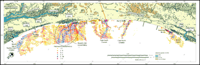
Paleochannel Incision Distribution and Fill ThicknessPaleochannels are observed throughout the sub-bottom data, providing information concerning the locations, sizes, geometries and relative ages of fluvial systems that previously occupied the area. Figure 14 illustrates the locations of paleochannels, as well as their orientations and associated fill thickness. It is apparent that the size and number of these features increase significantly toward the southwest.
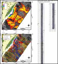
Two main paleochannel types are identified; Type I and Type II. Type I consists of large channels carved into underlying continental shelf deposits, most likely the results of Piedmont and Coastal Plain rivers cutting into subaerially exposed units during sea level low stands. Differential erosion of the underlying strata appears to be an important factor controlling the position of the channels. Many of the incisions occur adjacent to strong impedance reflections that are truncated at the surface, suggesting the presence of more resistant strata (Figure 13). All of these features appear to be truncated by a recent transgressive unconformity. Some portion of every channel's vertical extent has been eroded, making it impossible to assess original depth of incision or relative age according to vertical stratigraphic position. Upper surfaces of these channels are, in places, buried by surficial sediment deposits (Figure 13) and elsewhere exposed at the seafloor, both in broad expanses (Figure 12) and in the swales between sediment ridges (Figure 13). Attempts to penetrate these features with vibracores have been unsuccessful, suggesting that their upper surfaces may be lithified. Ages of the channels remain unknown, but the complex nature of some fill deposits indicate that they likely span a long period of pre-Holocene time. Type II paleochannels occur above the most recent transgressive unconformity and have been identified offshore of the Murrells Inlet and Waites Island areas. These features are generally much smaller than Type I paleochannels and appear to have less continuity in the cross-shelf direction. Because of this, the features are interpreted as geologically young tidal creeks, ephemeral swashes or small tidal inlets. Figure 13 (G - G') illustrates several of these incisions located immediately offshore of Murrells Inlet. The vertical stratigraphic positions of these features helps to determine their relative ages, but due to their limited extent, they have represented difficult targets for vibracoring operations. Fill deposits within the paleochannels generate two distinct seismic signatures and geometries. The first is characterized by prominent internal reflections, which identify bedding planes within the fill. Geometries of these reflections are commonly indicative of complex cut-and-fill structures and "nesting" of many incisions within a larger complex (Figures 12 and 13). Also, these geometries indicate the variable age of infill material, possibly due to reoccupation over time or multiple stages of backfill during transgression. The second common seismic signature is characterized by transparent fill, which indicate little or no internal variation in impedance (Figures 12 and 13). Transparent fill may represent rapid aggradation and channel filling with predominantly homogeneous sediment. Morphologically, paleochannel features prove to be quite variable throughout the study area. Incisions display steep sided, U-shaped and flat-bottomed cross-sectional morphologies (Figures 12 and 13). The features are also observed to be both symmetrical and asymmetrical, and often show evidence of lateral migration. Preserved portions of these channels range from tens of meters to several kilometers in width, and several meters to tens of meters in depth (Figures 12, 13 and 15). Highly variable cross-shelf morphologies are also observed. These include: 1) small localized drainage of the younger channels (Type II) identified offshore of Murrells Inlet (Figure 13) and Waites Island; 2) large straight channels with a single thalweg like the Cane North (Figures 12 and 14) and Pawleys Island channels (Figure 14); 3) large arcuate channels with a single thalweg like the Cane South channel (Figures 12 and 14); and 4) large integrated drainage networks with multiple thalwegs like the Murrells Inlet incised valley (Figures 13, 14 and 15).
|