
Digital Mapping Techniques '04— Workshop Proceedings
U.S. Geological Survey Open-File
Report 2004–1451
Progress Towards an Agency-Wide Geologic Map Database at Alaska Division of Geological & Geophysical Surveys
Alaska Division of Geological & Geophysical Surveys, 3354 College Road, Fairbanks, AK 99709-3707; Telephone: (907) 451-5027; Fax: (907) 451-5050; e-mail: Larry_Freeman@dnr.state.ak.us, Fred_Sturmann@dnr.state.ak.usINTRODUCTION
The Alaska Division of Geological & Geophysical Surveys (DGGS) has been producing geologic maps using a Geographic Information System (GIS) since 1983 (Davidson, 1998). To take advantage of changing GIS technologies and to be able to provide its customers with quality digital geologic data, DGGS reviewed the agency geologic map data structure and geologic mapping process. This review resulted in a new geologic map data model to be used in an agency-wide database system that will support DGGS geologic map production and geologic map data distribution into the future. DGGS geologists are now incorporating the basic components of that model into the process of compiling and producing new geologic maps utilizing the ESRI personal geodatabase framework.
DGGS intends to integrate the geologic map database into a comprehensive, centralized division-wide database that includes bibliographic information about DGGS publications, metadata about DGGS GIS datasets, geochemical analysis data, field locality information, and other data (Freeman, 2001; Freeman and others, 2002). DGGS recently moved its publications database and scanned document index (Davidson, and others, 2002) into the centralized database and began serving the publications through dynamic web pages, at http://www.dggs.dnr.state.ak.us/pubs/pubs.jsp. DGGS currently is developing a set of web-based forms that will incorporate DGGS metadata for project GIS data into the database (Browne and others, 2003) and will facilitate serving DGGS data through its publications web pages. DGGS also is developing a web-based search engine for DGGS geochemical data that will provide tabular views of the geochemical analyses and documentary data, including links to the original publications. Integrating the geologic map features into its division-wide database will allow DGGS to provide fully documented geologic map data to both web and local GIS clients in the same way that we will soon provide geochemical data.
LEGACY DGGS GEOLOGIC DATA
Geologic maps contain information about geologic features and earth materials that can be used in spatial analysis to facilitate earth resource assessment, development, and planning. Providing consistent, reliable geologic map data for decision makers in industry, government, and the general public is an essential function of a state geological survey. For DGGS to provide consistent data, it must have a consistent organization or data structure.
Legacy Data Structure
Older, legacy DGGS map data is structured in various ways. Most of the older legacy data is managed in a hierarchical GIS file directory system organized by project, map product, data type, and theme (Figure 1). Each thematic data set (e.g., “bedrock”) represents a different geometry, topologic grouping, or geologic feature classification. Attributes of each theme consist of codes that pertain to cartographic elements such as annotation or symbolic representation. To perform a geologic analysis, a data user needs to execute scripts to plot the information and needs a published map legend to determine the geologic context of the features. The existing directory and file structures, codes, and scripts have evolved and changed over time, from project to project, resulting in inconsistencies. Additionally, documentation of the legacy data is limited. As a result, to get full use of the DGGS geologic map data, users must depend on the specific knowledge and institutional memory of the people that created the data.
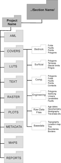 |
Figure 1. Hierarchical data structure for DGGS legacy maps, using the ESRI coverage data model. DGGS legacy map data is stored as coverages organized on a disk in subdirectories by Section (DGGS is divided into four sections, see http://www.dggs.dnr.state.ak.us/sections.html), Project, and Theme. For instance the bedrock fold features for any given map are stored as a coverage in the ../Covers/Bedrock/ subdirectory. The ../Comp./ subdirectory contains the data resulting from merging the bedrock geology data with the surficial geology data. |
DGGS legacy datasets can easily be converted into ESRI geodatabase format. However, direct conversion of the data does not take full advantage of the relational structure inherent in the ESRI geodatabase because the legacy datasets contain limited attribute context and documentation. Significant work is required to convert the cartographic codes contained in the legacy data into geologic data. Therefore, DGGS suspended data conversion until it could adopt a consistent data structure that could be used for creation and integration of new geologic maps as well as for conversion of legacy data.
DGGS GEOLOGIC MAP DATA MODEL
To update the agency GIS data structure and integrate the legacy geologic map data with other geologic data, DGGS staff in 2003 reviewed both the concepts recorded in geologic maps and the agency geologic map-making process. In this review a cross section of DGGS geologists examined the definitions of geologic maps and their components to determine the information that is essential to geologic maps. The review considered the existing DGGS data structure and mapping processes, the data structure of other agencies, and geologic map data models and lexicon concepts being developed by the North American Geologic Map Data Model Design Team (see http://nadm-geo.org/).
DGGS Geologic Map Definition
The DGGS discussions started by adapting the geologic map definition in Jackson (1997) to DGGS geologic maps:
A geologic map is a two-dimensional graphic representation of selected geologic features on a part of the earth as observed and interpreted by the authors. Composition, physical characteristics, and relationships of earth materials (rocks and unconsolidated surface materials) in the area covered by the map are portrayed by graphical juxtaposition, symbols, and labels; supplemented by explanatory material presented with the map.
In current practice, DGGS geologic maps portray bedrock and surface geologic features in particular areas of Alaska, typically coinciding with a USGS 15-minute series quadrangle map, and often at a nominal scale of 1:24,000 or 1:63,360. Generally these maps are distributed as a series of four maps with different themes including a comprehensive geologic map, a surficial geologic map, a bedrock geologic map, and an engineering geology map.
The geologic map components shown in Figure 2 represent the physical parts of the map as defined by the DGGS working group. Components are shade-coded to indicate whether the component is “essential”; without the essential components, a geologic map or data do not contain usable information.
 |
Figure 2. DGGS geologic map components as defined by DGGS geologists. Each component box contains a list of the elements of the component. |
The group also looked at the science and institutional processes involved in evolving empirical data (field observations, sample analyses, and geophysical measurements) to geologic map data and finally to a published product. Understanding these processes helps to better define the concepts and science logic that should be built into an object-relational database.
DGGS Geologic Map Conceptual Data Model
The map components identified by the DGGS working group are depicted as classes in a Unified Modeling Language (UML) Class diagram (Fowler and Scott, 2000). A “class” in a UML diagram (e.g., “data localities” in Figure 3) represents a group of objects that share characteristics and behavior. Within each class a box contains the attributes that characterize the class, and another box contains the operations that need to be carried out on the class or its attributes. Associated classes are tied together with connecting lines.
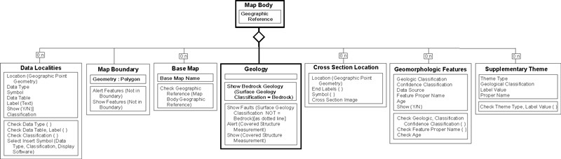 |
Figure 3. Geologic map body part of the DGGS data model, expressed as a UML class diagram. Each box represents a class. Within each class there are two sub-boxes; the upper sub-box is a list of attributes of the box, the second is a list of required actions. |
The data model is illustrated by a series of data centric, conceptual-level diagrams (Figures 3 and 4) that indicate the cartographic and scientific concepts contained in DGGS geologic maps and their essential components. For example, the “bedrock materials areas” class is a component of the geology class (Figure 4), which is in turn a component of the “map body” class (Figure 3), which is an essential component of a DGGS geologic map (Figure 2). The diagrams depict only the generalized, interpreted, and classified data that are contained in a completed geologic map. Operations in the class diagram are only those required to ensure data integrity and enforce standard vocabulary.
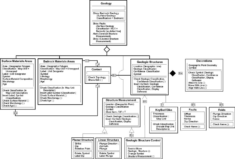 |
Figure 4. Subcomponents of the geology class of DGGS data model, expressed as a UML class diagram. Each box represents a class, within each class there are two sub-boxes; the upper sub-box is a list of attributes of the box, the second is a list of required actions. This diagram shows the geometric, logical, and content rules developed by DGGS staff for implementation into a geologic map database. |
The geologic map body component of a DGGS Geologic Map (Figure 3) is the “two-dimensional graphic representation of selected geologic features on a part of the earth” and is the essential core of the geologic map. Map identification, geographic reference, and explanation are already integrated into our geologic database to at least some degree. Within the geologic map body the most essential subcomponent is the geology class (Figure 4).
The geology class contains information about the earth materials and features depicted on a geologic map. The components of the geology class include earth materials (both bedrock and surficial) classification, which have an area (polygon) geometry; structural measurements, which have a point geometry; and geologic structures, which may be planar but are represented in the GIS with a line geometry. Earth material areas are grossly classified into surficial material areas and bedrock material areas, to reflect the agency mapping process and map distribution. Contacts comprise a class that defines the geometric boundaries of the earth material areas. The connecting line between contact and geologic structures (Figure 4) shows that geologic structures sometimes form the contacts between different earth materials. Structural measurements are subdivided into subclasses that have measured orientations and depict either planar or linear structures. Geologic structures have sub-classes including key beds, faults, and folds each with special characteristics.
Science and cartographic rules that apply to individual classes are listed in Figures 3 and 4 as actions, these rules apply only to the class, such as the rule: “geologic material classification must be listed in the description of map units” is represented as a “Check Classification” action. The connecting lines between classes depict science and cartographic rules between two classes. For example, a rule “lines representing contacts must be present on the boundary between two geologic material classification areas” is represented by the lines connecting the Contact class and the Bedrock and Surface materials areas classes.
Neither the process of generating a geologic map from empirical data nor the relationships between geologic map data and empirical data are represented in the model. For example, the trace of a fault on a geologic map is in part interpreted from geophysical data, spatial and time relationships between two adjoining geologic materials, and part from the author’s intuition; the DGGS model only captures that information in the Geologic Classification and Confidence Classification of the fault.
IMPLEMENTATION
The ESRI personal geodatabase model was used for DGGS mapping projects completed during 2004 (Athey and Craw, 2004). The geodatabase model was chosen because it supports geographically referenced polygon, line, and point geometries as feature classes. Additionally, spatial relationship rules between and within geometric classes can be enforced using topology classes, and logical rules between classes can be enforced using joins and relationship classes. Finally, the geodatabase can be used in a single user environment or in a multiple user environment (e.g., in ArcSDE, or Spatial Database Engine), allowing us the flexibility to integrate the geologic map database into our comprehensive agency-wide database and to take the same data structure and user interface out to remote field locations.
In the implementation of the DGGS geologic map data model in the geodatabase framework, each of the Geology subcomponent classes (Figure 4) was created as a feature class. Feature classes related by theme and geometric association are grouped into feature datasets (Figure 5). For example, the geodatabase used for the 2004 mapping projects (Figure 5) contains a “bedrock” feature dataset which includes feature classes “bedpolys” for bedrock materials areas, “bedcont” for contacts and faults, and “livfold_polyline” for folds. Geometric rules between contacts and polygons were enforced within the “bedrock” feature dataset using a topology class. This initial implementation did not include the use of relationship classes or domains to control the scientific language. DGGS plans to make a more robust use of topologic rules, relationship classes, and domains to ensure data integrity in future mapping projects.
Once the geologic map data model is fully developed and tested in the personal geodatabase, we will implement the model in an agency-wide spatial database system. The map data will be fully integrated with publications index information, dataset index information, field locality, analytical data, lexicon control, and project records contained in an agency-wide geologic map database (Freeman and others, 2002). This data integration will allow DGGS staff geologists to access geologic map features and analytical data from a single data repository while working at their networked desktop computers. When this geologic data integration is complete, DGGS staff geologists will be able to conduct spatial analysis and create and edit new geologic map data in a shared, multi-user environment.
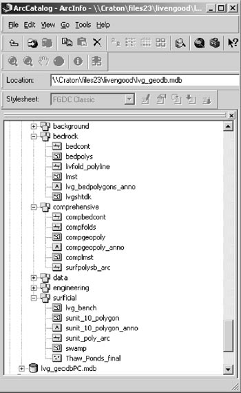 |
Figure 5. Screen shot of an ArcCatalog navigation tree of a geologic map database used for the 2004 DGGS geologic map products. |
REFERENCES
Athey, J.E., and Craw, P.A., 2004, Geologic maps of the Livengood SW C-3 and SE C-4 quadrangles, Tolovana mining district, Alaska: Alaska Division of Geological & Geophysical Surveys, Preliminary Investigative Report 2004–03, 24 p.
Athey, J.E., Werdon, M.B., Newberry, R.J., Szumigala, D.J., Craw, P.A., and Hicks, S.A., 2004, Geologic map of the Livengood SW C-3 and SE C-4 quadrangles, Tolovana mining district, Alaska: Alaska Division of Geological & Geophysical Surveys, Preliminary Investigative Report 2004–03a, 1 sheet, 1:50,000 scale.
Browne, C.L., Freeman, L.K., and Graham, G.R.C., 2003, The Alaska Division of Geological & Geophysical Survey’s Metadata Policy Development and Implementation, in Soller, D.R., ed., Digital Mapping Techniques ’03—Workshop Proceedings: U.S. Geological Survey, Open-File Report 03–471, p. 201–208, accessed at http://pubs.usgs.gov/of/2003/of03-471/browne/index.html.
Davidson, Gail, 1998, Can we get there from here? Experiences of the Alaska Division of Geological and Geophysical Surveys, in Soller, D.R., ed., Digital Mapping Techniques ’98—Workshop Proceedings: U.S. Geological Survey, Open-File Report 98–487, p. 13–15, accessed at http://pubs.usgs.gov/of/of98-487/davidson.html.
Davidson, Gail, Staft, Lauren, and Daley, E.E., 2002, The Alaska DGGS Scanning Project: Conception, Execution, and Reality, in Soller, D.R., ed., Digital Mapping Techniques ’02—Workshop Proceedings: U.S. Geological Survey, Open-File Report 02–370, p. 105––, accessed at http://pubs.usgs.gov/of/2002/of02-370/davidson.html.
Fowler, Martin, and Scott, Kendall, 2000, UML distilled: a brief guide to the standard object modeling language, second edition: Boston, Addison Wesley Longman, Inc., 186 p.
Freeman, Larry, 2001, A Case Study in Database Design: The Alaska Geologic Database, in Soller, D.R., ed., Digital Mapping Techniques ’02—Workshop Proceedings: U.S. Geological Survey, Open-File Report 01–223, p. 31–34, accessed at http://pubs.usgs.gov/of/2001/of01-223/freeman.html.
Freeman, Larry, Engle, Kathryn, and Browne, Carrie, 2002, Alaska Division of Geological & Geophysical Surveys Geologic Database Development—Logical Model, in Soller, D.R., ed., Digital Mapping Techniques ’02—Workshop Proceedings: U.S. Geological Survey, Open-File Report 02—370, p. 157–160, accessed at http://pubs.usgs.gov/of/2002/of02-370/freeman.html.
Jackson, J.A., ed., 1997, Glossary of Geology, 4th edition: Alexandria, Virginia, American Geological Institute, 769 p.