
|
|
|
||||
| Scientific Investigations Report 2005–5141 |
Hydrogeology of the Great Lakes Basin
Simulation of Ground-Water Flow
Implications and Limitations of the Scenario-Modeling Results
Figure 1. Surficial geology of the Great Lakes Basin (from Granneman...
Figure 2. A, Bedrock aquifer of the Great Lakes Basin (modified fro...
Figure 3. Model grid and boundary conditions for scenario model of ...
Figure 4. Diagrammatic section (A-A', fig. 3) through the scenario m...
Figure 5. One-percent scaled hydraulic-head sensitivity maps for A, ...
Figure 6. Transects for well locations relative to regional ground-w...
Figure 7. Percentage of pumped water from diversion of flow to river...
Figure 8. Effects of varying model parameters on the percentage cont...
Figure 9. Change in contributing area to basins by pumping 1 million...
Figure 10. Generalized block diagram of hydrogeology of southeast Wi...
Figure 11. Ground-water divides in southeastern Wisconsin (modified...
Figure 12. Percentage of pumping from various sources of water to w...
Figure 13. Model grid, boundary conditions, and hydraulic heads for...
Figure 14. River-stage elevation and selected hydraulic heads in tra...
Figure 15. Apparent percentage of ground-water pumpage with distanc...
Figure 16. Apparent percentage of ground-water pumpage with distance...
Figure 17. Flow through river bottoms, traveltime-delineated contrib...
Figure 18. Comparison of contribution to pumping from across predeve...
Table 1. Geologic unit and hydraulic parameter designation in region...
Table 2. Geologic unit and hydraulic parameter designation in region...
Table 3. Geologic-unit and hydraulic-parameter designation in river...
|
Multiply |
By |
To obtain |
|---|---|---|
|
Length |
||
|
foot (ft) |
0.3048 |
meter (m) |
|
mile (mi) |
1.609 |
kilometer (km) |
|
Area |
||
|
square mile (mi2) |
2.590 |
square kilometer (km2) |
|
Volume |
||
|
cubic mile (mi3) |
4.168 |
cubic kilometer (km3) |
|
Flow rate |
||
|
million gallons per day (Mgal/d) |
0.04381 |
cubic meter per second (m3/s) |
|
inch per year (in/yr) |
2.540 |
centimeter per year (cm/yr) |
|
Hydraulic conductivity |
||
|
foot per day (ft/d) |
0.3048 |
meter per day (m/d) |
|
Transmissivity* |
||
|
foot squared per day (ft2/d) |
0.09290 |
meter squared per day (m2/d) |
|
foot squared per day (ft2/d) |
7.4805 |
gallons per day per foot (gal/d/ft) |
Vertical coordinate information is referenced to the North American Vertical Datum of 1988 (NAVD 88).
Horizontal coordinate information is referenced to the North American Datum of 1983 (NAD 83).
Altitude or Elevation, as used in this report, refers to distance above the vertical datum.
*Transmissivity: The standard unit for transmissivity is cubic foot per day per square foot times foot of aquifer thickness [(ft3/d)/ft2]ft. In this report, the mathematically reduced form, foot squared per day (ft2/d), is used for convenience.
Abbreviated water-quality units used in this report: Chemical concentration is given in milligrams per liter (mg/L). Milligrams per liter is a unit expressing the concentration of chemical constituents in solution as weight (milligrams) of solute per unit volume (liter) of water. For concentrations less than 7,000 mg/L, the numerical value is approximately the same as for concentrations in parts per million.
Agreements between United States governors and Canadian territorial premiers establish water-management principles and a framework for protecting Great Lakes waters, including ground water, from diversion and consumptive uses. The issue of ground-water diversions out of the Great Lakes Basin by large-scale pumping near the divides has been raised. Two scenario models, in which regional ground-water flow models represent major aquifers in the Great Lakes region, were used to assess the effect of pumping near ground-water divides. The regional carbonate aquifer model was a generalized model representing northwestern Ohio and northeastern Indiana; the regional sandstone aquifer model used an existing calibrated ground-water flow model for southeastern Wisconsin. Various well locations and pumping rates were examined. Although the two models have different frameworks and boundary conditions, results of the models were similar. There was significant diversion of ground water across ground-water divides due to pumping within 10 miles of the divides. In the regional carbonate aquifer model, the percentage of pumped water crossing the divide ranges from about 20 percent for a well 10 miles from the divide to about 50 percent for a well adjacent to the divide. In the regional sandstone aquifer model, the percentages range from about 30 percent for a well 10 miles from the divide to about 50 percent for a well adjacent to the divide; when pumping on the west side of the divide, within 5 mi of the predevelopment divide, results in at least 10 percent of the water being diverted from the east side of the divide. Two additional scenario models were done to examine the effects of pumping near rivers. Transient models were used to simulate a rapid stage rise in a river during pumping at a well in carbonate and glacial aquifers near the river. Results of water-budget analyses indicate that induced infiltration, captured streamflow, and underflow were important for both glacial and carbonate aquifers; however, in many cases, traveltimes from the river to the well will limit river water from physically entering the well.
Ground water on the United States side of the Great Lakes Basin is used by about one-third of the residents or 8 million people (Granneman and others, 2000). Ground-water withdrawals amount to about 1,500 Mgal/d (Solley and others, 1998). Only about 5 percent of this water is consumed; the remainder returns as streamflow to the lakes (Granneman and others, 2000). About 1,000 mi3 of ground water is stored in the Great Lakes Basin, about the same amount of water as is stored in Lake Michigan (Granneman and others, 2000). Ground water is an important part of the Great Lakes ecosystem—ground water sustains low flow and habitats associated with wetlands, lakes, and streams tributary to the Great Lakes. Ground-water withdrawals may deplete or reduce inflow of ground water to these surface-water bodies (Granneman and others, 2000).
The Great Lakes Charter (1985) is an agreement between the governors of the Great Lakes States and the Canadian territorial premiers that establishes water-management principles for Great Lakes water and sets the framework for protecting Great Lakes waters from diversion and consumptive uses. The Great Lakes Charter Annex (2001) specifically includes ground water as part of the Great Lakes waters and "provide[s] a framework for increased use of scientific information regarding surface and ground water in the Great Lakes Basin" (Speck, 2003).
In 2001, the U.S. Geological Survey (USGS) began an international project, in cooperation with the Great Lakes Protection Fund, focusing on basinwide ground-water information needs for the Great Lakes. Project goals included raising awareness of the linkage between ground water, streams, and the Great Lakes; increasing understanding of the effects of ground-water withdrawals on ground-water divides at the edges of the Great Lakes Basin; estimating ground-water discharge to streams tributary to the Great Lakes; and establishing ongoing coordination of ground-water data and information relevant to the Great Lakes hydrologic budget.
The objectives of the subproject described herein are to use ground-water flow models to increase the understanding of the effects of ground-water withdrawals on ground-water flow near (1) the regional ground-water divide between the Great Lakes Basin and the Mississippi River Basin and (2) areas adjoining riverine systems that are tributaries to the lakes. A generic "scenario" model can be used to represent a type of ground-water system (as opposed to a specialized model of a particular ground-water system); scenario models often are used to describe fundamental aspects of a ground-water system without the additional labor and costs of collecting and analyzing calibration data. Because they represent simplified, hypothetical systems, scenario models can clearly identify and isolate processes that affect the system and can define the system exactly (Reilly and Harbaugh, 2004). Scenario models have been used to examine boundary conditions (Franke and Reilly, 1987), contributing areas to wells (Morrisey, 1989; Reilly and Pollock, 1993, 1995), and model calibration (Hill and others, 1998).
This report presents the results and implications of scenario numerical modeling of ground-water flow near the boundaries of the Great Lakes Basin. Two primary regional aquifer systems were modeled to determine the effects of ground-water withdrawals on the regional ground-water divides. Results from additional scenario modeling illustrate the effects of stream stage and bank storage on ground-water withdrawals in primarily glacially derived river-aquifer systems
MODFLOW-2000 (Harbaugh and others, 2000; Hill and others, 2000) was used for all the scenario models to simulate advective ground-water flow near the ground-water divides and river/aquifer systems. MODFLOW-2000 is a modular, finite-difference program that can be used to simulate one-, two-, quasi-three, and full three-dimensional ground-water flow. The modular construction of the program allows the simulation of processes such as evapotranspiration, recharge from precipitation, and ground-water interaction with lakes, rivers, and other surface-water features. MODFLOW-2000 is designed to simulate aquifer systems in which (1) saturated-flow conditions exist, (2) Darcy's Law applies, (3) the density of ground water is constant, and (4) the principal directions of horizontal hydraulic conductivity or transmissivity do not vary within the system (Leake, 1997). MODFLOW-2000 can be used to model steady-state or transient ground-water flow.
As is the case in most places, ground water in the Great Lakes Basin moves in local and regional flow systems. Ground water in local flow systems is recharged locally by precipitation and commonly travels relatively short distances underground before discharging to a stream, lake, or wetland (Granneman and others, 2000). Ground-water levels in local aquifers usually mimic topography, and local ground-water flow divides often are coincident with surface-water divides. Regional ground-water flow systems usually have longer flow paths than local flow systems do and typically are deeper than local systems; confining units commonly separate local from regional flow systems (Granneman and others, 2000). Regional ground-water flow usually discharges to large lakes and rivers (or in many cases, wells) and occurs in glacial and bedrock aquifers. Ground-water levels in regional aquifers may not necessarily mimic topography, and regional ground-water divides often do not coincide with surface-water divides (Eberts and George, 2000; Feinstein and others, 2004).
Aquifers in the Great Lakes Basin range from extremely permeable glacial deposits to less permeable, but still heavily used, sandstone and carbonate bedrock. Glacial deposits usually consist of a complex assemblage of unconsolidated sediments including clay, till, sand, and gravel (fig. 1; Granneman and others, 2000), primarily as a result of at least four continental glaciations. In some parts of the region, glacial deposits are more than 1,000 ft thick. As thickness increases, the complexity of the sediment assemblage usually increases. Often, these surficial aquifers interact considerably with local rivers, streams, and lakes. These surficial aquifers are tapped by domestic users and small municipalities and industries throughout the region and have been the subject of numerous studies by universities, consultants, and local, state, and Federal government agencies.
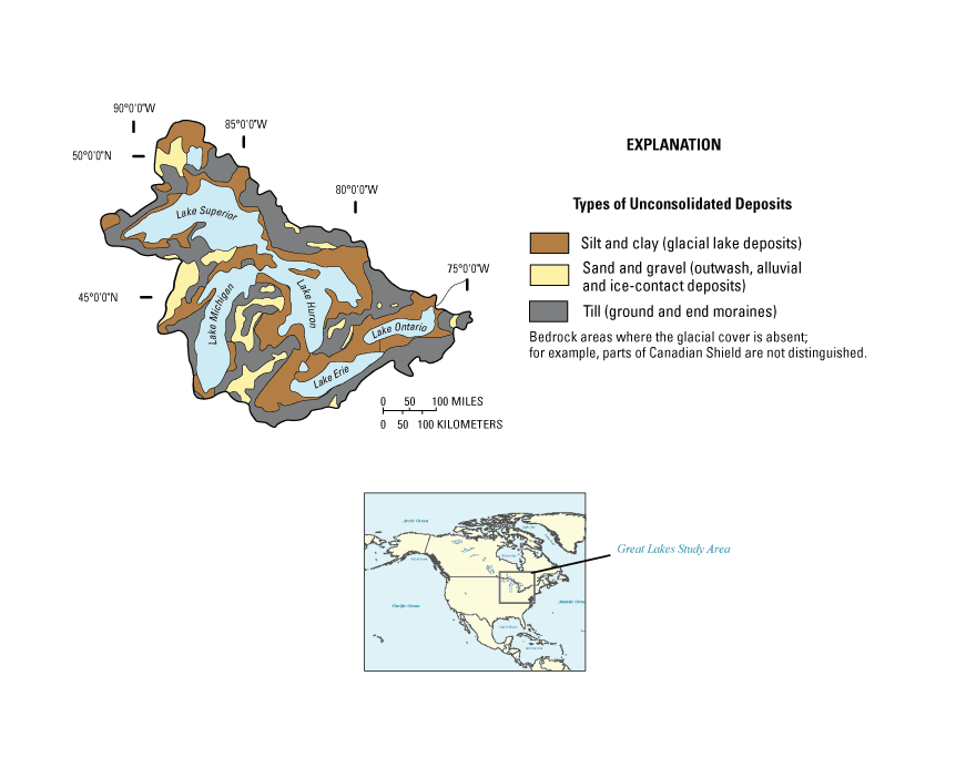
Figure 1. Surficial geology of the Great Lakes Basin (from Granneman and others, 2000).
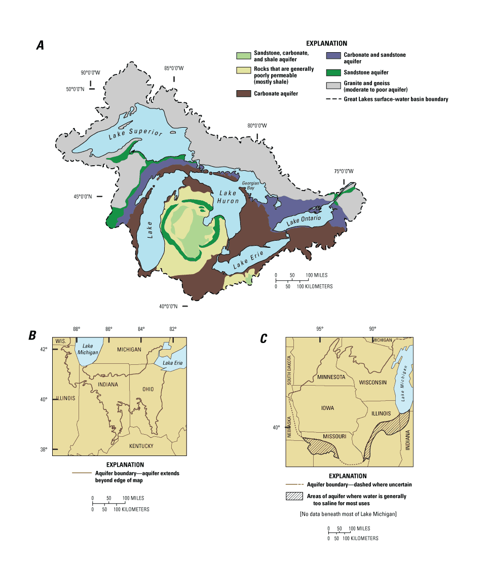
The primary bedrock aquifers in the Great Lakes Basin are shown in figure 2. The extent, thickness, hydraulic properties, and general directions of flow in the most heavily used bedrock aquifers in the Great Lakes Basin have been described in publications from regional aquifer studies by the USGS (numerous reports listed in Sun and others, 1997) and by state and local agencies (Bleuer and others, 1991; Batten and Bradbury, 1996; Passero and others, 1981). The two primary regional bedrock aquifers that are at the edge of the Great Lakes surface-water basin are a carbonate aquifer and a sandstone aquifer (fig. 2 B,C; note that both aquifers extend beyond the surface-water basin boundary). Ground-water divides define the ground-water basin boundaries, which are transient barriers to ground-water flow and are established by a combination of natural and human-induced stresses.
Scenario ground-water flow modeling was used to increase understanding of what changes might occur over time in the regional ground-water flow system when ground water is withdrawn near the divide; specifically, in regional bedrock aquifers in the Great Lakes Basin. An additional objective was to increase general understanding of what processes are active in a river/aquifer system when stream-stage variations and pumping coincide. To this end, three aquifer-system models are presented, based on three hydrogeologic settings within the Great Lakes Basin: (1) regional carbonate aquifer, (2) regional sandstone aquifer, and (3) glacial aquifer coincident with a river. The regional carbonate aquifer is modeled with a generic numerical ground-water flow model, based on general characteristics of the regional carbonate aquifer in northwestern Ohio and northeastern Indiana; the regional sandstone aquifer is modeled with a previously developed calibrated numerical flow model, and the glacial aquifer adjacent to a river is modeled with a generic numerical ground-water flow model. The following sections describe the hydrogeologic framework used as the basis for the models, the numerical model frameworks, and model simulations and sensitivity analyses of these three models.
The regional carbonate aquifer, which encompasses approximately 44,000 mi2 in western Ohio, Indiana, eastern Illinois and southern Michigan (fig. 2), is overlain predominantly by surficial material consisting of end moraine and ground moraine (till), outwash sediments, and lacustrine deposits (Bugliosi, 1999). Because these deposits represent three major stages of Wisconsinan-age glaciations, the resulting landscape and internal structure of the glacial deposits is a mixture of unconsolidated deposits (Bugliosi, 1999; Casey, 1999). Although absent in places at the southern extent of glaciations, these deposits are more than 400 ft thick in areas underlain by preglacial buried valleys (Bugliosi, 1999). Much of the carbonate aquifer in northwestern Ohio and northeastern Indiana is overlain by relatively thin (less than 100-ft-thick) clay-rich glacial deposits consisting of lake plain, ground moraine, or lacustrine deposits (Pavey and others, 1999). Commonly, at the base of these surficial deposits and above the regional carbonate aquifer is either a more permeable sand or sand and gravel deposit (Soller and others, 1999; Angle and others, 2003) or a hardpan till, which can have a significantly lower permeability than the surficial units above or the carbonate units below (Angle and others, 2003).
The regional carbonate aquifer is composed primarily of limestone and dolomite of Middle Devonian to Early Silurian age, and most of the aquifer is semiconfined by surficial deposits. The lower boundary of flow for the regional carbonate aquifer consists of shale and shaley limestone of Late Ordovician age (Bugliosi, 1999). Carbonate rocks that make up the regional carbonate aquifer thicken from a few feet in southwestern Ohio/southeastern Indiana to approximately 2,500 ft where they dip into the Michigan Basin (Bugliosi, 1999; Casey, 1999). Several faults intersect the regional carbonate aquifer; but, because the maximum offset is less than 200 ft and confining units are not brought into contact with the carbonate aquifer, the faults are not thought to interrupt regional ground-water flow (Bugliosi, 1999). Ordovician shale and shaley limestone of the Maquoketa Group underlie the regional carbonate aquifer.
Recharge to the regional carbonate aquifer is by percolation through overlying surficial deposits. Recharge estimates to the carbonate aquifer range from 0.14 to 6.3 in/yr (Eberts and George, 2000). Regional discharge boundaries include Lake Erie and most of the major streams within the area, including the Ohio River (Bugliosi, 1999; Eberts and George, 2000).
Lateral no-flow boundaries of the carbonate aquifer are on the east, west, and north where the aquifer dips into the Appalachian, Illinois, and Michigan Basins, respectively. The limit of potable water (defined by less than 10,000 mg/L dissolved solids) is near the edge of these basins (Eberts and George, 2000). The potentiometric-surface map for the regional carbonate aquifer shows that flow is a subdued reflection of land surface (Eberts and George, 2000). However, a comparison of regional flow paths and the position of the surface-water divide that separates streams that flow toward the Atlantic Ocean (St. Lawrence River Basin) and those that flow toward the Gulf of Mexico (Ohio River Basin) shows that deep regional flow paths sometimes cross the drainage divides, although the amount of water diverted from one major stream basin to another likely is small relative to the flow in the aquifer (Eberts and George, 2000).
Eberts and George (2000) state that an estimated 13,000 Mgal/d discharges naturally from ground water to streams in the area: therefore, the aquifer system is not being stressed by pumping at a regional scale. However, the regional carbonate aquifer is used by industries, municipalities, and rural domestic users. In 1990, approximately 433 Mgal/d was withdrawn from the surficial glacial deposits and regional carbonate aquifer, with only about 15 percent taken from the carbonate aquifer (Beary, 1993). From 1990 to 2000, population in the area of the regional carbonate aquifer rose approximately 10 percent, as did public-supply withdrawals, but total ground-water use rose approximately 21 percent (U.S. Geological Survey, 2004). On the basis of the potentiometric surface of the regional carbonate aquifer (Eberts and George, 2000), the ground-water basin was divided into the Great Lakes drainage area, the Mississippi River drainage area, and the area of the ground-water divide (based on the counties that contained the divide). Between 1990 and 2000, the largest ground-water use increase was from the Lake Erie part of the ground-water drainage (38 percent) and is attributed primarily to large limestone quarries in Michigan and Ohio. Total ground-water use (from either the glacial or carbonate aquifer) in areas that encompass the regional carbonate ground-water divide increased 25 percent from 1990 to 2000 (from about 50 to 63 Mgal/d). The average water use (inclusive of all water-use categories) for the divide areas was 0.38 Mgal/d from ground water; the median and maximum reported pumpage for this same area was approximately 0.08 and 5.3 Mgal/d, respectively.
Ground-water flow and storage of ground water within the regional carbonate aquifer is affected by topography and hydraulic characteristics of the surficial and carbonate-aquifers (Bugliosi, 1999). The rate of areal recharge to the carbonate aquifer depends on the thickness and permeability of overlying surficial deposits (Eberts and George, 2000).
The glacial deposits that make up the surficial aquifer overlying the carbonate aquifer can vary widely over short distances, as evidenced by data from aquifer tests within these materials; transmissivities of glacial aquifers range from 300 to 69,700 ft2/d, and storage coefficients range from 0.00002 to 0.38 (Joseph and Eberts, 1994; Eberts and George, 2000). Individual (local) glacial aquifers can supply large yields of ground water (Ohio Department of Natural Resources, Division of Water, 1970). However, transmissivities throughout the glacial aquifers are likely on the lower end of the range described above because many aquifer tests are done only where significant quantities of water are available from the glacial deposits. Eberts and George (2000) used a regional ground-water flow model to estimate horizontal hydraulic conductivities for moraine deposits (21.3 ft/d) and for outwash deposits (168 ft/d) overlying the regional carbonate aquifer. Calibrated-model estimates of vertical hydraulic conductivity for these materials range from 0.0001 to 0.77 ft/d (Eberts and George, 2000, p. C13).
Transmissivities for the regional carbonate aquifer, determined from aquifer tests, range from 70 to 28,000 ft2/d; storage coefficients range from 0.00001 to 0.01 (Joseph and Eberts, 1994). The flow and storage of ground water in the regional carbonate aquifer occurs primarily along joints, fractures, and bedding planes (Casey, 1999). Ground-water flow through the rock matrix is insignificant when compared to the quantity of water that moves through joints, fractures, and bedding planes (Casey, 1999). The uppermost part of the regional carbonate aquifer is the most highly fractured zone of the aquifer, as a result of unloading, weathering, and dissolution by ground water (Casey, 1999). Horizontal and vertical hydraulic conductivities of the Ordovician interbedded shale and limestone underlying the regional carbonate aquifer are estimated to be 10-5 to 10-7 ft/d, based on core analysis (Casey, 1999).
A scenario model was developed that is generally based on hydraulic, geographic, and physiographic information on the regional carbonate aquifer within the Midwestern Basin and Arches region. The scenario model (fig. 3) was approximately 190 mi by 190 mi and consisted of a grid of 282 rows and 281 columns and 3 geologic units discretized into 11 layers. The model grid was variably spaced—1 by 1mi on the outer edges and 0.5 by 0.5 mi in the center. The model was bounded on the east by a general head boundary, representing a regionally extensive lake through the three units. The western boundary was a large river, representing a regional sink of ground-water flow. The northern and southern boundaries were no-flow boundaries, representing the edges of the aquifer material (or bounding flow lines). Additional tributaries that flow to the east and west boundaries were placed in the model to allow for local discharge and drainage. Areal recharge from precipitation was applied.
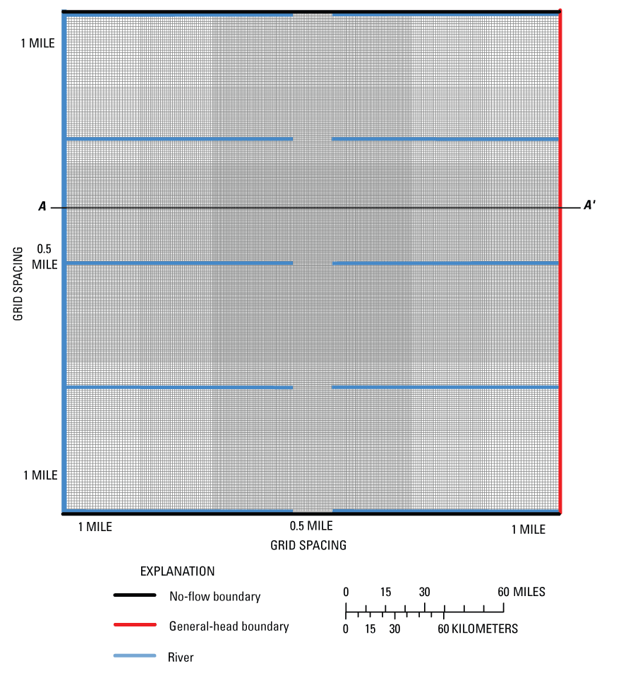
Figure 3. Model grid and boundary conditions for scenario model of the regional carbonate aquifer.
The aquifer system was represented as three distinct geologic units--an uppermost unit to represent the surficial glacial material, a lowermost unit to represent the regional carbonate aquifer, and an intermediate unit between the glacial material and carbonate aquifer (fig. 4). On the basis of the previous ground-water flow model (Eberts and George, 2000), each unit was assigned uniform horizontal and vertical hydraulic conductivities and general thickness representative of the aquifer system (table 1). The top of the model was represented as the water table in the surficial deposits and initially had a gradient approximately equal to what was measured by Eberts (1999). The bottom of the carbonate unit was a no-flow boundary.
Table 1. Geologic unit and hydraulic parameter designation in regional carbonate aquifer model.
| Geologic unit | Number of layers | Horizontal hydraulic conductivity (feet/day) | Vertical hydraulic conductivity (feet/day) | Approximate thickness (feet) |
|---|---|---|---|---|
| Glacial | 5 | 21.3 | 2.13 | 40 |
| Intermediate | 1 | 21.3 | 2.13 | 10 |
| Carbonate | 5 | 5 | 0.5 | 400 |
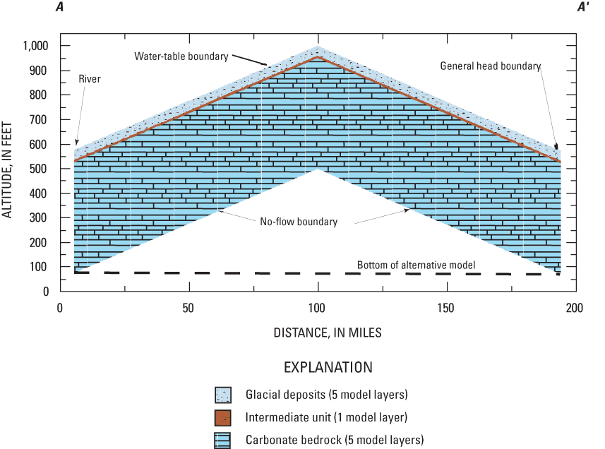
The Great Lakes are topographically low; therefore, they function as discharge areas or sinks for the ground-water-flow system under natural flow conditions (Granneman and others (2000). The general head boundary on the eastern boundary of the model was placed to represent a regionally extensive lake (figs. 3 and 4). The General Head Boundary package, commonly used to simulate lakes, is used to simulate conditions where the amount of flow through the boundary depends on the hydraulic heads in the boundary cell and the adjoining cell within the model; the amount of flow is directly proportional to a conductance term (McDonald and Harbaugh, 1988). The conductance term was initially set to 0.2 ft2/d. Each layer in the model terminates in the east by a general head boundary, with the hydraulic head in units 1 and 2 set to an elevation of 575 ft. The hydraulic head for the general head boundary in unit 3 was initially set to 580 ft, which generated a slight upward gradient in this vicinity of the model. This distribution of general head boundaries created the upward gradient necessary to model discharge into the simulated lake. Sensitivity of the general head boundary to pumping near the ground-water divides is discussed later in this report.
The River Package (McDonald and Harbaugh, 1988) was used to simulate the large river on the western boundary of the model (figs. 3 and 4) and all the tributaries to this river and the lake. River cells were placed only in the upper layer of the model. The amount of flow through the boundary of the river cell (bottom of the cell) is directly proportional to the hydraulic-head difference between the cell containing the river and the cell immediately beneath it. The bottom elevations and stages of the rivers in the scenario model varied with the top elevation of the upper model layer; but as elevation decreased, bottom elevation was lowered to account for bigger rivers in the lower part of the basin. Riverbed hydraulic conductivity values were set to 0.25 ft/d but were varied during the sensitivity analyses and model runs as parameters. The width of the river increased with decreasing elevation, thereby varying riverbed conductance (riverbed hydraulic conductivity x width of river in cell x length of river in cell/thickness of riverbed in cell).
Eberts and George (2000) used 0.001 – 11.8 in/yr for recharge into the glacial deposits overlying the regional carbonate aquifer, with general head boundaries removing excess water. The average recharge rate into the glacial deposits is 2.38 in/yr, based on the water budget for that model. Analysis of Wolock (2003) indicates that the average recharge rate for the area underlain by the regional carbonate aquifer is 3.84 in/year. These average values are consistent with but generally lower than those reported from more local-scale studies by Holtschlag (1997) and Dumouchelle and Schiefer (2002), Because the scenario model does not simulate smaller scale discharge areas explicitly (smaller tributary rivers, seeps, springs), an effective recharge rate was calculated from the Eberts and George model (2000) that accounts for smaller scale recharge and discharge water balances. An effective recharge rate of 0.61 in/yr to the water table was used in the scenario model on the basis of this calculation.
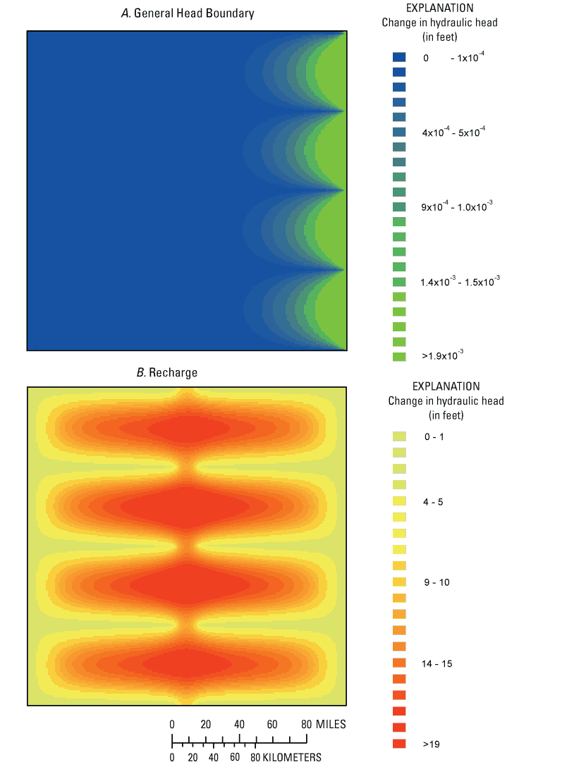
Several model input parameters in the scenario model were examined by parameter sensitivity analysis. Sensitivity analysis is a process used to assess the effect of model input parameters on model outputs, which typically are hydraulic heads. This process provides information on which model parameters are most important to the simulated system. The parameters that affect diversions of water across ground-water divides are largely the same as those parameters affecting hydraulic heads. Consequently, the parameters to which hydraulic heads are most sensitive should be the parameters that are important to the understanding of ground-water diversion across divides.
The input parameters included hydraulic conductivity of each unit (K1, K2, K3), vertical conductance of each unit (K1V, K2V, K3V), recharge (R), general head boundary conductance terms (GHB1, GHB2, GHB3), and riverbed conductance of the tributaries and boundary river (KTrb, KBrb). A hypothetical well also was simulated to determine its influence on heads. One-percent sensitivity maps were examined to determine the influence of a 1-percent change in a parameter value on hydraulic heads. Figure 5 shows example cases of parameters that had small effects (GHB3) and large effects (R) on hydraulic heads. As inferred from the sensitivity maps, the parameters that had the least effect on hydraulic heads in the vicinity of the regional divide were the general head boundary conductance terms and the riverbed conductance of the boundary river. The parameters that had the greatest effect on hydraulic heads in the vicinity of the divide were KTrb (conductance of the tributary riverbeds), R (areal recharge to the glacial deposits), and K3 and K3V (horizontal and vertical hydraulic conductivity of the carbonate aquifer). Further analyses of how these parameters affect ground water near the regional divide are described in the following section.
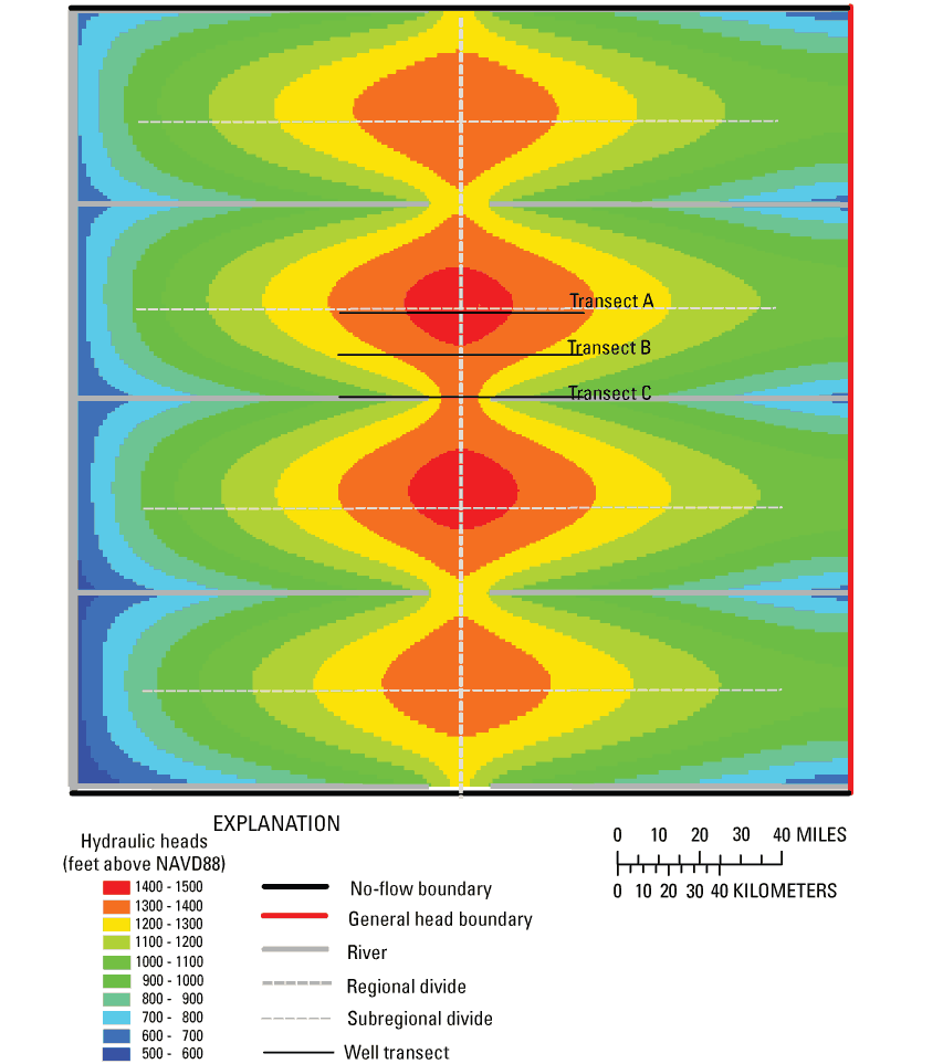
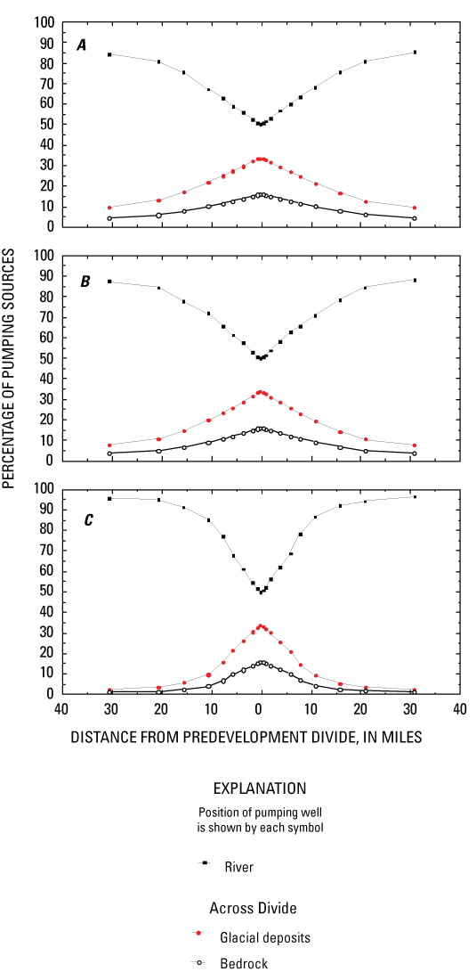
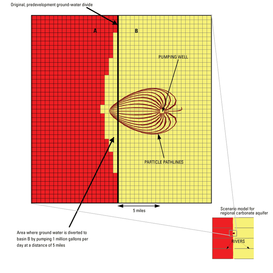
Several model simulations were used to demonstrate the effect of pumping near the simulated regional ground-water divide. To do this, the model was initially separated into discrete zones so that flows between zones could be tabulated. These zones were established under nonpumping conditions, with the central boundary along the regional divide (fig. 6). The between-zone flows (BZF) were determined using the ZoneBudget program (Harbaugh, 1990). To evaluate the effect of pumping, the initial BZFs were determined for nonpumping conditions. For the purpose of computing BZFs from the glacial units to the carbonate, the upper two units (glacial deposits) were grouped together. Simulated pumping conditions used a single well in the upper part of the carbonate aquifer (unit 3) at various locations along three transects across the regional divide (fig. 6). The well locations were placed to examine the BZFs, in particular with respect to the regional divide and tributary rivers. Transect A was along the subregional divide (between the tributaries), transect B was intermediate between the subregional divide and tributary rivers, and transect C was near the tributaries (fig. 6). The expected effect of a pumping well near the divide was that water would be induced to flow across the divide; the BZFs of most concern were those across the predevelopment divide in both the carbonate and glacial aquifers.
In nonpumping conditions, by definition, no water flows across the divide; therefore, under pumping conditions, the volume of flow across the divide can be considered as a percentage of the pumping rate. Thus, one way to examine the hydraulic effects of the pumping well near a ground-water divide was to examine plots of well location and the volume of water as a percentage of the pumping rate that flows across the divide. Figure 7 illustrates the percentage of pumped water contributed from across the regional divide through glacial and carbonate sources, and from flow captured from entering nearby rivers, along the three transects (fig. 6). If a pumping well is close to a tributary river, more of the pumped water is derived from that tributary river and, therefore, less is drawn across the divide (fig. 7C). Alternatively, if a pumping is farther from the potential effects of a river (fig. 7A), more water is diverted across the predevelopment divide (that is, the pumping divide moves away from the pumping). Regardless of whether the well is near a subregional divide or near a river, as a pumping well is moved closer to the regional divide, the percentage of water captured from entering nearby rivers (or induced from the rivers) decreases as the percentage of water diverted across the regional divide through the glacial or carbonate bedrock increases. In this model, when the simulated well is placed away from a river and 10 mi from the regional ground-water divide, as much as 35 percent of the water withdrawn is diverted across the regional ground-water divide (≈25 percent bedrock, ≈10 percent glacial; fig. 7A).
Because parameters in the model that may affect diversion of water across the divide are largely the same as those that might affect hydraulic heads, a sensitivity analysis was done. Hydraulic heads are most sensitive to changes in pumping rates, tributary riverbed conductance, and recharge. Because a percentage of pumped water is used, variation in pumping rate only slightly affects the percentage of water induced or diverted across the divide (fig. 8). The effect of changing recharge (+ 50 percent) on the percentage of pumping diverted across the divide is also shown (fig. 8A); along with changes in horizontal hydraulic conductivity of unit 2(divided by 10, fig. 8B), and changes in tributary riverbed conductance (+100 percent, fig. 8C). Tributary riverbed conductance had the most significant effect on diversions of water across the divide, albeit small (less than 5 percent, fig. 8C). Changes in recharge and hydraulic conductivity of unit 2 had virtually no effect on the amount of water diverted across the divide (fig. 8A,B). However, if local variations in recharge or hydraulic conductivity existed, they would undoubtedly have some effect on the amount of water available to pumping, and therefore, the amount of water diverted across the divide.
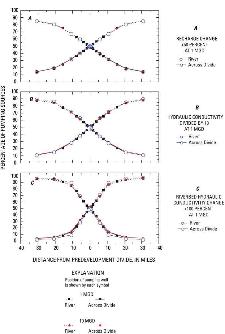
Figure 9 illustrates the overall effect of a pumping well near a predevelopment ground-water divide between two ground-water basins, as simulated with the scenario model of the regional carbonate aquifer. The predevelopment (or prepumping) ground-water divide denotes the boundary between two ground-water basins A and B. After pumping reaches steady state, the divide is moved away from the well in basin B, and the contributing area to the well includes an area originally included in basin A.
The regional sandstone aquifer is present in southeast Minnesota, Iowa, northern Illinois, northeast Missouri, Michigan, and southern Wisconsin (Olcott, 1992) (fig. 2). It is a complex multilayer aquifer system with individual units separated by confining or semiconfining units; it is overlain by the Maquoketa Shale, a regional semiconfining unit (fig. 10). A previously developed numerical model of ground-water flow in southeastern Wisconsin (Feinstein and others, 2004) was used for the scenario modeling described in this report; therefore, a detailed description of the geology in southeast Wisconsin is included in the following paragraphs.
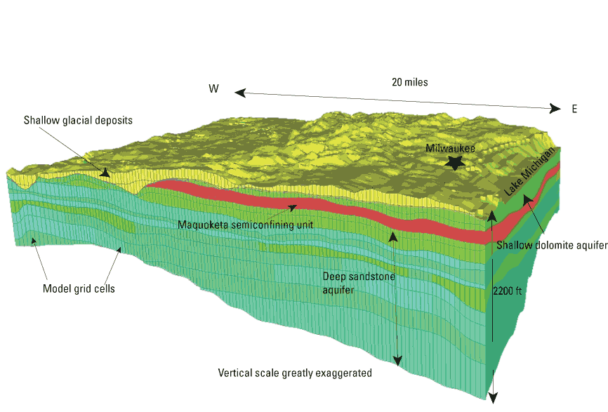
Glacial deposits or a shallow bedrock aquifer overlie the regional sandstone aquifer and confining unit in southern Wisconsin; the glacial deposits have varied lithology and complex stratigraphy (Olcott, 1992) (fig. 10). Ice advances across Wisconsin and Michigan encountered vast areas of sandstone and crystalline bedrock in the northern parts of these states. Fragments of these rocks were transported and deposited farther to the south as extremely permeable, sandy material that forms productive aquifers. Where dolomitic rocks were encountered by the ice, the resulting glacial sediments are calcareous and rich in clay (Olcott, 1992). The glacial deposits range from less than 50 to 400 ft in thickness. In southwestern Wisconsin, much of the regional sandstone aquifer system is either uncovered by glacial deposits or overlain by very thin glacial deposits (less than 50 ft thick). In southeastern Wisconsin, the glacial deposits overlie a shallow fractured dolomitic aquifer that is either unconfined (hydraulically connected to the overlying permeable glacial deposits) or locally semiconfined by glacial till (Southeastern Wisconsin Regional Planning Commission, 2002) (fig. 10).
The regional sandstone aquifer is composed primarily of sandstone in the lower part and interbedded shale and limestone or dolomite in the upper part (Olcott, 1992). Most of the regional sandstone aquifer is at least semiconfined by the surficial aquifer or the Maquoketa Shale (Southeastern Wisconsin Regional Planning Commission, 2002) (fig. 10). The regional sandstone aquifer is underlain by Precambrian crystalline rocks (Olcott, 1992; Southeastern Wisconsin Regional Planning Commission, 2002). The thickness of the rocks that make up the regional sandstone aquifer can range from 200 ft to as much as 1,500 ft where the units dip into the Michigan Basin. Several nearly vertical faults offset bedrock units in southern Wisconsin and may affect regional ground-water flow as they offset lithologic units; however, the complexity of the faults and their effects on ground-water flow are not well known. Several deep buried valleys are incised into the bedrock in southeastern Wisconsin to a depth of 500 ft (Southeastern Wisconsin Regional Planning Commission, 2002).
Recharge to the aquifers in southern Wisconsin is primarily by percolation through overlying surficial deposits. Recharge estimates to the surficial aquifers range from less than 3 percent (about 1 in/yr) of the annual precipitation in areas with poorly permeable surficial deposits to about 10-15 percent (3.2-4.8 in/yr) of the annual precipitation (Southeastern Wisconsin Regional Planning Commission, 2002; Feinstein and others, 2004). Buried bedrock valleys also are a potential source of recharge to the deep sandstone aquifer (Feinstein and others, 2004). Regional discharge locations include areas beyond the shoreline of Lake Michigan, streams within the area, and pumping wells tapping the deep sandstone aquifer.
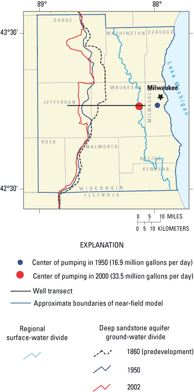
A water-table map for the region (Southeastern Wisconsin Regional Planning Commission, 2002; map 21) shows that shallow ground-water flow in the glacial deposits is defined by a ground-water divide that separates ground-water flow to the east and to the west. This divide roughly corresponds to the regional surface-water divide to the northwest of Milwaukee (fig. 11). Regional ground-water flow in the deep sandstone aquifer is generally toward Lake Michigan and toward major pumping centers west and southwest of Milwaukee (fig. 11). The regional ground-water divide for the deep sandstone aquifer is several miles west of the surface-water divide (fig. 11); therefore, deep regional flow paths cross the surface-water drainage divides. Historically, vertical flow in the vicinity of Lake Michigan was upward from the deep sandstone aquifer toward the lake; however, over the past 100 years, numerous deep production wells in the Milwaukee area have penetrated the sandstone aquifer, and pumping has reversed the vertical flow directions between the aquifer and the lake (Feinstein and others, 2004).
Although ground water is not the primary source of water supply for the region, it is an important source for many communities. In southeast Wisconsin, the glacial aquifers, the shallow dolomite aquifer, and the regional sandstone aquifer are all used by industries, municipalities, and domestic users. In 1995, 68 percent of municipal water systems in this area were supplied by ground water. In 1995, approximately 93 Mgal/d was withdrawn from these aquifers, representing about 30 percent of the total water use for the area. This was an increase in ground-water use of about 30 percent from 1985. (Southeastern Wisconsin Regional Planning Commission, 2002). During 1990-2000, for a seven-county area in southeastern Wisconsin, the majority of ground-water withdrawals (52 percent) were from the deep sandstone aquifer (Feinstein and others, 2004).
The rate of recharge to the regional sandstone aquifer depends upon the thickness and permeability of overlying surficial deposits and the vertical permeability and thickness of the Maquoketa Shale (Feinstein and others, 2004; Southeastern Wisconsin Regional Planning Commission, 2002). The glacial deposits that make up the surficial aquifer overlying the regional sandstone aquifer are extremely variable and are related to the origin and environment of deposition of the materials. Hydraulic-conductivity estimates were made of the buried valley deposits by quantifying the percent of fine-grained material reported on well logs. Three categories of hydraulic conductivity were defined—high, moderate, and low—to simplify the mapped distribution of glacial permeability. Calibrated horizontal- and vertical-hydraulic-conductivity estimates of glacial deposits are given in table 2.
| Geologic unit | Number of layers | Horizontal hydraulic conductivity (feet/day) | Vertical hydraulic conductivity (feet/day) | Approximate thickness (feet) |
|---|---|---|---|---|
| Quaternary and Silurian/Devonian aquifer | 5 | 0.2 - 100 | 0.001 - 1 | 25-400 |
| Confining units* | 4 | 0.0003 - 0.3 | 5x 10 -6 -0.01 | 0-500 |
| Regional sandstone aquifer system | 8 | 0.24 - 8.4 | 4x10 -5 -0.04 | <2000 |
*Confining or semiconfining units include the Maquoketa Shale and Sinnipee Group.
Hydraulic-conductivity distribution within the shallow dolomite and the confining units is related to the distribution of fine-grained lithology and to weathering and development of fractures (table 2). Estimates of hydraulic conductivity for the regional sandstone aquifer system were based on averaging results of aquifer tests in southeastern Wisconsin and dividing the resulting transmissivities by the average thickness of the aquifer (Feinstein and others, 2004). These results were refined by use of deep-well specific-capacity data (Eaton and others, 1999). Spatial variations in hydraulic conductivity were derived by use of geologic logs and distribution of fine-grained material in each of the stratigraphic units. Estimates of vertical hydraulic conductivity were made in a similar way. The range of calibrated horizontal and vertical hydraulic conductivities is given in table 2.
A three-dimensional numerical model was developed by Feinstein and others (2004) using MODFLOW (McDonald and Harbaugh, 1988) to simulate and assess the historical and current (2004) ground-water withdrawals on ground-water conditions in southeastern Wisconsin. This model, hereafter called the southeast Wisconsin model, was used for the scenario modeling and is therefore presented in detail in the following paragraphs.
The southeast Wisconsin model consists of "farfield" and "nearfield" parts; the farfield encompasses parts of Michigan, Illinois, and Wisconsin and is used for basic boundary conditions for the nearfield (Feinstein and others, 2004). The nearfield part of the model encompasses a seven-county area in southeastern Wisconsin (fig. 11) and is the focus of the model results. The model consists of 205 rows and 166 columns, variably spaced so that most of the nearfield grid spacing is 2,500 ft and maximum spacing in the farfield is 20 mi. The model has 18 layers of varying thickness (table 2). The nearfield is bounded on the east by general head boundary, representing Lake Michigan. Hydraulic heads are fixed in the outer part of the farfield, based on previous ground-water studies (Mandle and Kontis, 1992). Flows through the north, south, and west boundaries of the nearfield are controlled by heads in the inner farfield, which are allowed to vary, except near major rivers and streams. Areal recharge from precipitation is applied, and heads in the nearfield are free to respond.
The aquifer system is represented as three major units—the surficial glacial material and upper dolomite aquifer, the Maquoketa Shale, and the lower sandstone aquifer. The bottom of the lower sandstone aquifer is a no-flow boundary.
The general head boundary on the eastern boundary of the southeast Wisconsin model represents Lake Michigan. Each layer in the model terminates in the east by a general head boundary, with hydraulic heads in all model layers set to a uniform elevation of 577 ft. The conductance term was set very high to model negligible resistance across the lakebed. In this way, simulated ground-water levels are nearly equal to the stage of Lake Michigan. The use of a separate package facilitates analysis of Lake Michigan's influence on the model mass balance (Feinstein and others, 2004).
Major rivers, streams, and lakes (other than Lake Michigan) in the nearfield are simulated with the River Package (McDonald and Harbaugh, 1988). Riverbed conductances for rivers were set to agree with previously estimated riverbed conductance from Krohelski and others (2000). Lakebed leakances varied to allow most of the ground-water/surface-water exchange along the perimeter of the lakes.
Effective recharge to the aquifer system was estimated from stream base flow by use of base-flow separation and regression techniques; values ranged from approximately 1.0 to 14.0 in/yr. In the western part of the modeled area not covered by stream base-flow studies, recharge was set to 4.5 in/yr, the average rate for southeast Wisconsin. Recharge was applied to the water table in the southeast Wisconsin model with the Recharge Package in MODFLOW (McDonald and Harbaugh, 1988).
The southeast Wisconsin model was initially a steady-state model representing predevelopment conditions (no pumping), followed by a transient model that simulates the effects of pumping on regional water levels from 1864 to 2000. During model calibration, output heads and fluxes were compared to measured or estimated water levels, and streamflows and model parameters were adjusted to improve model fit. Statistical measures of model sensitivity were generated (Feinstein and others, 2004).
Seventy-three target hydraulic heads for the upper part of the aquifer system were generated from water-table maps (Southeastern Wisconsin Regional Planning Commission, 2002) and were assumed not to have changed since development. Forty-four hydraulic heads for the deep sandstone aquifer were taken from a potentiometric surface map of predevelopment conditions and from compiled well data (Feinstein and others, 2004). Cross plots of measured heads versus simulated heads were used, along with statistical measures, to iteratively minimize the variability in fit of the model with observed data. The calibrated model has a good statistical fit with available measured data overall, with larger variations seen in the deep sandstone aquifer targets (Feinstein and others, 2004).
Multiple head and flow targets were used to calibrate the southeast Wisconsin transient flow model. Measured water levels, trends in water-levels, vertical-gradient information, and stream fluxes were compared to model output. Water level measurements from 1940 to 2000 in 56 wells were separated into 10 time intervals; and, statistically they compared well to model output for the same time period. Ten wells completed in the deep sandstone aquifer had long-term semicontinuous records, which were compared to simulated water-level trends for the same periods. The rate and magnitude of water-level decreases due to pumping were reflected in the model output. Vertical hydraulic head profiles were measured in seven deep sandstone wells and were compared with model output; similar slopes were found where the Maquoketa Shale is thin or absent, and the absence of vertical gradients in the eastern part of the study area were reflected in model output (Feinstein and others, 2004). Fourteen streamflow-gaging stations were used to calculate base flow (from ground water) for comparison with model output. Although close agreement with model output was not obtained in every case, the overall sum of modeled fluxes agrees well with the overall measured fluxes (Feinstein and others, 2004).
Several hydraulic parameters or parameter sets in the southeast Wisconsin model were varied systematically and the changes in heads at observed locations were determined so that comparisons between parameters could be made. These results were used to determine which parameters had a large influence on the results of the model. In the steady-state model, the most influential parameters are recharge, hydraulic conductivity of the glacial units, and the hydraulic conductivity of the lower sandstone aquifer. The model has little sensitivity to the hydraulic conductivity of the riverbeds. The vertical hydraulic conductivity of the Maquoketa Shale has little influence on heads in the glacial units but a significant influence on heads in the deep sandstone aquifer (Feinstein and others, 2004).
In the southeast Wisconsin transient model, pumping rates, specific storage, and specific yield were added to the group of hydraulic parameters tested with a sensitivity analysis. Small changes in the pumping rates have a large influence on model heads. Horizontal hydraulic conductivity of the sandstone also affects hydraulic heads significantly in the deep sandstone aquifer.
In the southeast Wisconsin model, actual pumping rates and well locations were used to demonstrate the effects of long-term pumping in southeastern Wisconsin by simulating ground-water levels between 1864 and 2000. For the purposes of the scenario modeling, a transect was established in the southeast Wisconsin model to determine the effect of pumping on diversions across the sandstone aquifer predevelopment divide (fig. 11). Hypothetical well locations within the sandstone aquifer were established along the transect. The wells were placed in the deep sandstone and pumped at rates of 5 and 20 Mgal/d. Only the scenario-model well was pumping in these simulations. Flow contributions from each source of water to the well 10 years after the onset of pumping were collected by use of ZoneBudget (Harbaugh, 1990) and were compared to predevelopment (or nonpumping) flow budgets.
Six sources of water to pumping wells were delineated in the budget analysis of the nearfield model:
As the pumping well is moved from west to east, across the divide, differing sources of water to the pumping well become apparent. At 5 mi west of the predevelopment divide, 85 percent of water to the well is from captured or induced flow from various rivers and lakes (not including Lake Michigan), and the remainder (15 percent) is from diversion across the predevelopment divide or removal from aquifer storage (fig. 12). As the well is moved east, closer to the predevelopment divide, the contribution from rivers and lakes decreases dramatically, as the diversion across the predevelopment divide through the sandstone aquifer proportionally increases (fig. 12). When the pumping well is east of the predevelopment divide, the percentage of pumped water induced across the divide is greater, peaking at nearly 50 percent when the well is 2 mi east of the predevelopment divide. Initially (predevelopment), the ground-water divide in the sandstone aquifer was west of the divide in the glacial aquifer, which probably accounts for the peak diversion occurring when the pumping is 2 mi east of the original location of the divide in the sandstone aquifer.
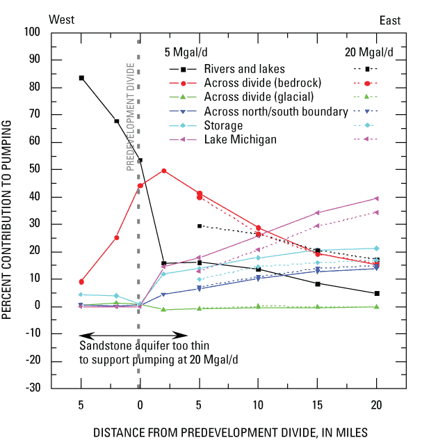
The amount of flow induced across the predevelopment glacial divide is nearly zero in the scenario model, regardless of the position of the well from west to east. As the well is moved east toward Lake Michigan, the contribution of pumped water from rivers and lakes (other than Lake Michigan) is less, and the diversion of water across the predevelopment divide through bedrock also is less (fig. 12); however, water from Lake Michigan, from storage, and from changes in flow across the northern and southern boundary of the model increases.
The sandstone aquifer is too thin to support the higher pumping rates (greater than 15 Mgal/d) west of the predevelopment divide. However, in contrast to the regional carbonate aquifer model, changes in pumping rates do affect the percentage of flow to wells contributed from various sources (fig. 12). On the east side of the predevelopment divide, the contribution to pumped water is greater from rivers and lakes under higher stresses and less from Lake Michigan and from storage in the aquifer. Although possibly a result of the boundary condition used for simulating Lake Michigan, the percent contribution from across the predevelopment divide through the sandstone stays nearly the same under the higher stress.
The regional carbonate and regional sandstone aquifers are both dissected by rivers. Often, water-supply wells are placed in the bedrock or glacial aquifers near rivers in an attempt to induce infiltration and increase production capacity (Sheets and others, 2002). Two scenario models were developed to illustrate the transient nature of river/aquifer interactions—one for a well completed in a carbonate aquifer near a river and one for a well completed in a glacial aquifer near a river. These scenario models were much smaller in scale than the previous scenario models discussed in this report and help to illustrate the local-scale phenomenon associated with river/aquifer interaction. The models used modifications of aquifer parameters from the regional carbonate aquifer model, described previously, to illustrate the contribution of sources of water to wells near a river before, during, and after a rise in stage in the river.
The hydraulic properties for the river/aquifer interaction models (table 3) are much the same as described earlier for the regional carbonate aquifer with two notable exceptions. Because pumping was simulated in a carbonate aquifer (beneath glacial material) near a river, the intermediate unit was assigned the same horizontal and vertical hydraulic conductivity as the carbonate aquifer, and the thickness of the glacial material was increased to 50 ft (table 3). Also, because public water supplies in the glacial aquifers of the Upper Midwest part of the United States are typically completed in thick, permeable sands and gravels, horizontal and vertical hydraulic conductivities of the glacial-aquifer pumping model were assumed to be near the highest of those reported by Eberts and George (2000) and the thickness of the glacial deposits was increased to 100 ft (table 3). These values are lower than those typically found in glacial and alluvial buried valleys of southwestern Ohio (Dumouchelle, 1998) but consistent with those found in outwash plains not necessarily associated with buried valleys. Specific yields and storage coefficients for all units are listed in table 3.
Table 3. Geologic-unit and hydraulic-parameter designation in river/aquifer interaction models.
| Geologic unit | Number of layers | Horizontal hydraulic conductivity (feet/day) | Vertical Hydraulic conductivity (feet/day) | Approximate thickness (feet) | Storage coefficient | Specific yield | |||
|---|---|---|---|---|---|---|---|---|---|
| Glacial pumping | Carbonate pumping | Glacial pumping | Carbonate pumping | Glacial pumping | Carbonate Pumping | ||||
| Glacial | 3 (1*) | 168 | 21.3 | 0.77 | 2.13 | 100 | 50 | 10 | 0.2 |
| Intermediate | 1 | 5 | 5 | 0.5 | 0.5 | 25 | 25 | 10 | 0.2 |
| Carbonate | 5 | 5 | 5 | 0.5 | 0.5 | 375 | 425 | 10 | 0.2 |
*For the carbonate aquifer, the glacial unit was represented by one layer.
An estimate of 0.25 ft/d for vertical riverbed hydraulic conductivity was based on Calver (2001) and is consistent with other studies done in Ohio (Moreno, 1988; Childress and others, 1991; Dumouchelle, 1998), Indiana (Duwelius and others, 2001), and Michigan (Luukkonen and others, 2000). Conductance of all riverbed cells (riverbed hydraulic conductivity x length of river x width of river/riverbed thickness) was assumed to be 37,500 ft/d. Sensitivity analyses were done on all hydraulic parameters to determine the influence of these parameters on hydraulic heads in the model; these will be described later in this report.
The basic framework for the scenario models describing river/aquifer interactions is illustrated in figure 13. The model consists of a uniform grid of 139 rows and 179 columns, approximately 50 ft on a side. The boundaries along columns 1 and 179 are general head boundaries, allowing flow to enter the model, in response to the hydraulic heads at the boundary and conductance terms for the boundary condition. The boundaries along rows 1 and 139 are no-flow boundaries; no flow enters or leaves the model across these boundaries. The MODFLOW River Package (McDonald and Harbaugh, 1988) was used to simulate an approximately 150-ft-wide nonpenetrating river in the center of the model (fig. 13).
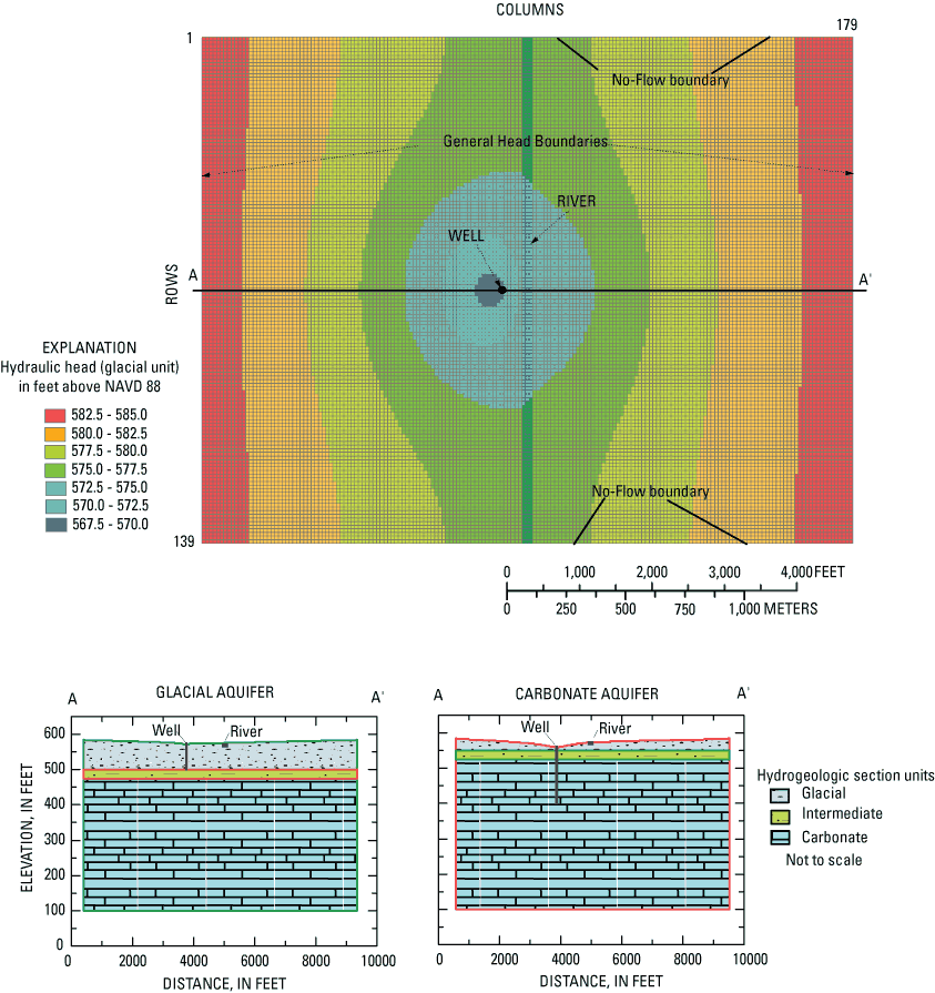
Three units were represented in each model. Layer designations, assigned hydraulic conductivities, and thicknesses are given in table 3 and are shown in figure 13. The thickness of the glacial unit in the river/carbonate aquifer model is less than when pumping was simulated in the glacial aquifer, because thicker parts of glacial aquifers are generally more likely to be used for water supply instead of the deeper carbonate units (fig. 13).
The general head boundaries along columns 1 and 179 of the model are set to 584 ft, 583.5 and 583 ft in elevation for units 1, 2 and 3, respectively, generating an initial downward gradient of approximately 0.002 ft/ft. Along with the initial river-surface elevation (stage), this generates an initial horizontal hydraulic gradient of about 0.002 ft toward the river for each unit.
The simulated river in the model is assumed to be 5 ft deep, with an initial stage of 575 ft and a riverbed elevation of 570 ft. Recharge to the model and the riverbed hydraulic conductivity were uniform at 7 in/yr and 0.25 ft/d, respectively. Hydraulic heads in the glacial aquifer, before any stage change in the river, are shown in figure 13; 1 Mgal/d is the pumping rate in the glacial aquifer.
Because transient changes in river stage can affect contributions to pumping wells, the river stage was changed transiently as shown in figure 14, simulating a rainfall-runoff response. A total of seven model stress periods were used. An initial 365-day model stress period with static river stage was followed by a 0.5-day, 7.5-ft stage rise. This is followed by a gradual decline in river stage over the next 30 days (four stress periods) and a final 365-day stress period at the same river stage as the initial period. Each period included pumping. Hydraulic heads output from the end of a previous simulation were used as the initial conditions of the transient model.
Several hydraulic parameters were input to a parameter-sensitivity analysis, which indicates how much a 1-percent change in a particular parameter might affect the hydraulic heads in a model. Parameters examined included horizontal hydraulic conductivity of each unit (K1, K2, and K3), vertical hydraulic conductivity of each unit (K1V, K2V, and K3V), riverbed hydraulic conductance (Crb), areal recharge (R), and the general head boundary conductance for each unit (GHB1, GHB2, GHB3). The sensitivity analysis was completed with a 1.0 Mgal/d pumping well approximately 275 ft from the simulated river. The sensitivity of hydraulic heads to changes in pumping rate (Q) also was examined.
When pumping is simulated in the glacial aquifer, hydraulic heads in unit 1 are most sensitive to K1 and Q, by more than an order of magnitude over K3 and Crb. Hydraulic heads in unit 3 are most sensitive to K3, K1, Q, followed by K1V and Crb. Variation of general head boundary conductance has the least effect on hydraulic heads in both units. The relative sensitivities remain consistent throughout each stress period, except that Crb becomes a very important parameter in relation to unit 1 hydraulic heads during the initial river-stage rise.
When pumping is simulated in the carbonate aquifer, hydraulic heads in unit 3 are most sensitive to Q, K3, and K3V, and K1, based on the maximum value of hydraulic-head change due to a 1-percent change in the parameters. General head boundaries have the least effect on hydraulic heads in both units. These relative sensitivities remain consistent throughout each stress period in the model.
To determine the sources of water to a pumping well near a river during a stage increase, a single well pumping 1 Mgal/d was used. In each case, the scenario model was first run without pumping. By subtracting pumping and nonpumping flows, the amount of flow for a particular time in the model to and from various sources was obtained. These sources include
Each of the scenario models was run several times to determine how the sources of water to a pumping well changed with respect to the distance between the well and river. Although transient models were used, traveltimes were not accounted for in the budget analysis; therefore, the flows calculated from given water sources represent what would eventually reach the well if conditions remained constant. However, as the river stage decreases, the flow conditions change before all the water from the various sources reaches the well. The river-stage increase does temporarily alter the ground-water system, and at least some of the effects of the stage rise may eventually reach the well.
For the river/glacial aquifer model, the simulated pumping well was fully penetrating in unit 1. Eleven independent model runs were tested with the pumping well being placed at various distances between 75 ft and 2,075 ft from the river. Simulated hydraulic heads for observation points directly below the river are shown on figure 14A for a pumping well approximately 250 ft from the river. Before the river-stage increase, the hydraulic gradient is from the carbonate unit to the glacial aquifer, and to the river (fig. 14A). Sources of water to the pumping well under constant river-stage conditions are shown in figure 15A. For example, for a well at 250 ft from the river, none of the pumped water originates from induced infiltration, about 85 percent of the pumped water is captured streamflow, and about 15 percent of water is underflow. As the pumping well is moved farther away from the river, proportionally less water is from underflow and more from captured streamflow. With constant river-stage conditions and the parameters included in this model, induced infiltration becomes nearly zero within 100 ft of the river.
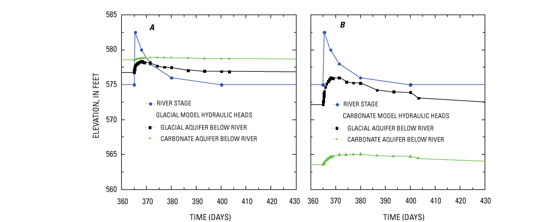
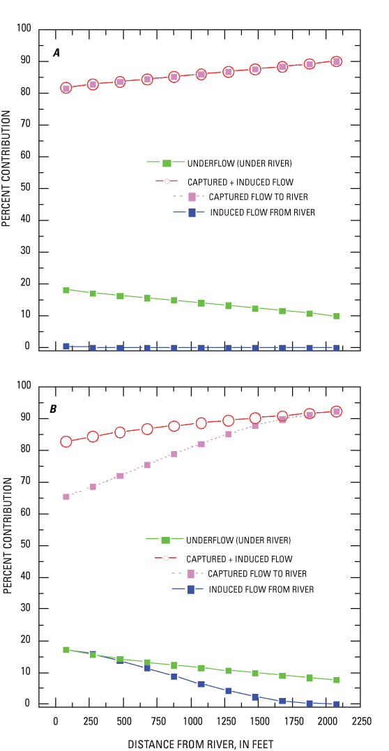
For the river/carbonate aquifer model, the open interval of the simulated pumping well spanned 400 to 525 ft in elevation, comparable to many wells in the regional carbonate aquifer that are completed in the upper 100-150 ft of the aquifer. As in the river/glacial aquifer model, 11 independent model runs were tested with the pumping well being placed at various distances between 75 ft and 2,075 ft from the river. Simulated hydraulic heads for observation points directly below the river are shown on figure 14B, for a pumping well approximately 250 ft from the river. Before the river stage increase, the hydraulic gradient is from the river to the glacial aquifer to the carbonate aquifer (fig. 14B). Sources of water to the pumping well under steady river-stage conditions are shown in figure 15B. For example, for a well within 250 ft of the river, about 70 percent of the water is captured streamflow, about 15 percent is induced infiltration and the remaining 15 percent is from underflow. As distance from the river to pumping well is increased, induced inflow and underflow decreases while captured streamflow increases.
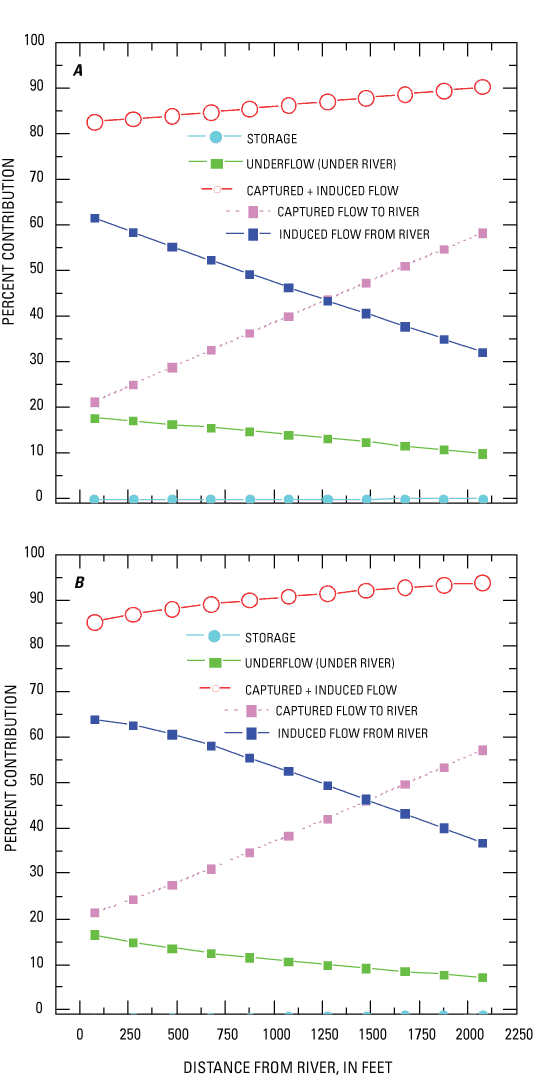
When the modeled river stage was much higher than "normal," simulating the peak rainfall-runoff, the eventual sources of water to the pumped well (what would reach the well if the high-stage conditions were sustained) were quite different than under normal river stage. The hydraulic heads during high stage (fig. 14) show flow from the river to the glacial and carbonate aquifers. Figure 16 shows the apparent percentage of ground-water pumpage from various sources in response to pumping, if the high stage was sustained long enough for the water to reach the well. In the river/glacial aquifer model (fig. 16A) when the well is within 250 ft of the river, about 60 percent of the water that would eventually reach the well in response to high stage is from induced infiltration; about 25 percent is from captured streamflow, and the remaining 15 percent is from underflow. The distribution in sources to the well in the river/carbonate aquifer model is similar (fig. 16B). Although the combined total of captured streamflow and induced infiltration is the same as under "normal" stage, the contribution of each component changes dramatically in response to increased hydraulic-head gradient between the river and well (fig. 14A, fig. 15A,B and 16A,B). As the pumping well is moved farther away from the river, the amount of induced infiltration decreases and is inversely proportional to the captured streamflow.
The traveltimes from these various sources of water can be very important with regard to the contributing recharge areas for each model (fig. 17). MODPATH (Pollock, 1994) was used to place hypothetical particles of water on the water table under static conditions in the aquifer and river (at 365 days before the increased stage), with the effective porosity of all units set at 0.2. The resulting traveltime-delineated contributing recharge areas are shown in figures 17A and 17C.
For the river/glacial aquifer model, water does not flow from the river to the well because simulated flow volumes through the river bottom were negative, indicating ground-water flow into the river (fig. 17A). If hypothetical particles of water are released at the peak stage, the particles of water released in the river travel from the river toward the well but do not reach the well within 365 days, primarily because the river stage and the gradient returns to pre-peak conditions quickly relative to the ground-water traveltimes. The traveltime-delineated contributing recharge area does not change appreciably during transient changes in river stage; however, the status of the river changes from gaining water from ground water to losing during high stage (fig. 14A and fig. 17A,B).
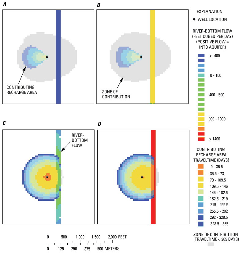
In contrast, the river/carbonate aquifer model indicates that when particles are released before peak stage (fig. 17C) and during peak stage (fig. 17D), each of the contributing recharge areas intersects the river, and flows in the river near the well are negative. Both conditions indicate flow out of the river and toward the well, no matter what the river stage. However, when the river stage rises, the gradient increases between the river and well and particles of water flow toward the well at a higher rate. As with the river/glacial aquifer model, the traveltime-delineated contributing recharge areas for pumping in the river/carbonate aquifer model are similar from static conditions to high stage, because the stage returns to pre-peak conditions relatively quickly and the change in rate due to a rapid stage rise is still small relative to the overall traveltime.
Ground-water traveltime and recharge areas of wells are directly related to formation values of effective porosity. As the effective porosity of the formation is increased, the velocity at which water travels decreases, and therefore the traveltime within the formation increases. Conversely, decreased effective porosity increases velocity and decreases traveltime. For the purposes of modeling, effective porosity is independent of other hydraulic parameters controlling hydraulic head and gradients; changes to effective porosity only affect traveltimes and therefore the size and shape of contributing recharge areas. Sheets (1994) and Schalk (1996) show the effects of changing effective porosity in models on the size and shape of contributing recharge areas in glacial aquifers.
After the river-stage rise, flow volumes through the river bottom increase greatly in both aquifer models because of the increased hydraulic gradient between the river and aquifer. As river stage returns to normal, flows from the various sources of water to the well return to the steady-state conditions. In the case of the river/glacial aquifer model, it is unlikely that river water will enter the well unless the river stage remains high for a period longer than the traveltime because, even under pumping conditions, the "natural" flow is toward the river. In the case of the river/carbonate aquifer model in the vicinity of the river under pumping conditions, flow is from the river toward the well.
If a pumping well is near a river, a rise in the stage will result in a pulse of river water being induced into the adjacent aquifer. If the traveltime of the induced water to the well is less than the period of the river-stage rise, then river water actually enters the well. As the distance between the well and river increases, traveltimes increase, and the likelihood that a short-duration stage change will supply additional water to the well is greatly diminished.
As mentioned at the outset of this report, the two areas of greatest concern with regard to ground water in the Great Lakes Basin are withdrawals that may affect the regional divide between the Great Lakes and Mississippi Basins and withdrawals near tributaries to the lakes. With regard to these issues, the four scenario ground-water flow models yielded expected results in some ways but produced some unexpected results as well.
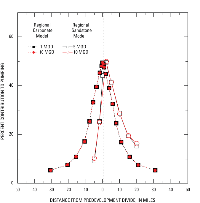
Although the regional carbonate aquifer model uses realistic hydraulic parameters from the regional carbonate aquifer in Ohio, the model is neither linked to a specific region nor calibrated to real-world data. The regional sandstone aquifer model, on the other hand, relies on modifications to an existing, calibrated model for southeastern Wisconsin. In both regional models, the effect of a hypothetical pumping well on the ground-water divide was independently tested for a series of locations. In both regional scenarios, pumping a well near the ground-water divide moves the predevelopment divide. The degree to which the divide is affected depends on a number of variables, but a significant proportion of the pumped water is supplied to the well from the opposite side of the predevelopment ground-water divide. In the regional carbonate aquifer model, the percentage of pumped water crossing the divide ranges from about 20 percent for a well 10 mi from the divide to about 50 percent for a well adjacent to the divide. In the regional sandstone aquifer model, the percentage ranges from about 30 percent for a well 10 mi from the divide to about 50 percent for a well adjacent to the divide; when pumping on the west side of the divide, within 5 mi of the predevelopment divide, results in at least 10 percent of the water being diverted from the east side of the divide. Even though these two models are substantially different in design and complexity and simulate different aquifers, both yield similar results and both indicate that a pumping well can affect regional ground-water divides even when the well is miles away from the divide (fig. 18).
Previous studies using scenario models have investigated the interaction of wells and rivers (Reilly and Pollock, 1993, 1995), but models examining the effects of changing river stages are less common. The effect of a change in river stage on sources of water to wells was investigated with two smaller-scale transient scenario models, one with a pumping well in a carbonate aquifer and one with the well in a glacial aquifer. These two models were constructed similarly, in that glacial sediments overlie carbonate rocks and a river is simulated within the glacial sediments; the differences are in glacial-sediment thickness, screen depth, and hydraulic properties. In both river/aquifer scenarios, water is induced from the river to the well, and the well intercepts or captures water that would have reached the river; the real-world effect is a reduction in streamflow. Both models indicate that these sources of water are a significant proportion of water pumped from a well, even for wells more than 2,000 ft from the river. However, the transient nature of river-stage rise means that the conditions generally do not last long enough for induced river water to reach the well, unless the traveltime to the well is shorter than the duration of stage change in the river.
Understanding and considering the effects of wells on ground-water divides and surface-water flows is an important component of basinwide water-management principles. The scenario models presented in the report can assist water-resources managers in evaluating real-world situations, but the limitations of such models must factor into such evaluations. Ground-water-flow models are numerical representations of natural flow systems, and they cannot duplicate the natural flow system exactly. Assumptions and simplifications are necessary in any modeling effort. In particular, the regional carbonate aquifer model is highly generalized; however, the regional sandstone aquifer model was calibrated to real-world data, and the similarity of the scenario outcomes indicates the regional carbonate aquifer model could be useful. Both of the regional model scenarios are steady-state simulations, which cannot factor in changing conditions over time. Neither were potential effects of multiple pumping wells on one or both sides of divide investigated. Although temporal effects were simulated in the river/aquifer scenarios, the hydrogeology was highly simplified, and the various factors that may affect the results were not investigated; for example, the effects of multiple wells, variable and temporally changing streambed hydraulic conductivity, and spatially varying recharge.
The USGS, in cooperation with the Great Lakes Protection Fund, used ground-water flow models to increase the understanding of the effects of ground-water withdrawals on ground-water flow near (1) the regional ground-water divide between the Great Lakes Basin and the Mississippi River Basin and (2) areas adjoining riverine systems that are tributaries to the lakes. Four models of ground-water flow are described in this report: two regional aquifer models and two local river/aquifer models. The two regional aquifer models were built to examine the effects of pumping on ground-water divides. The models included a generalized model of a regional carbonate aquifer and a model of ground-water flow in a specific regional sandstone aquifer in southeastern Wisconsin.
The regional carbonate aquifer model was based on hydraulic properties of the aquifer in northwestern Ohio and northeastern Indiana but was generalized to the extent that it did not represent any specific area and was not calibrated. The regional sandstone aquifer model was previously developed for southeastern Wisconsin; this model used site-specific data and was calibrated to measured head data from the area. The effect of a hypothetical pumping well on the ground-water divide was independently tested in each regional aquifer model for a series of locations ranging from on the divide to more than 10 mi from the divide. Although both models simulated the effects of pumping a bedrock aquifer with similar estimated hydraulic conductivities, internal and external boundary conditions varied widely because the purposes of compiling the models were different. Internal boundary conditions, such as thickness of units (therefore transmissivity of aquifers) and vertical hydraulic conductivity of confining beds were very dissimilar between the models. Although the two models varied in construction and development, results of percentage of flow to hypothetical wells near the ground-water divides yielded similar results, based on water budget analyses. Substantial proportions of total pumpage result from diversion of ground-water across the predevelopment ground-water divides, due to pumping within 10 mi of the divides. In the regional carbonate aquifer model, the percentage of pumped water crossing the divide ranges from about 20 percent for a well 10 mi from the divide to about 50 percent for a well adjacent to the divide. In the regional sandstone aquifer model, the percentage ranges from about 30 percent for a well 10 mi from the divide to about 50 percent for a well adjacent to the divide; when pumping on the west side of the divide, within 5 mi of the predevelopment divide, results in at least 10 percent of the water being diverted from the east side of the divide.
Because glacial aquifers are above the carbonate and sandstone aquifers and much of the pumping in these aquifers is near rivers, additional scenario modeling was done to examine the effects of pumping near rivers. The modeling was limited to pumping in a glacial aquifer underlain by a carbonate aquifer and to pumping in a carbonate aquifer near rivers. A transient model was used to simulate a rapid stage rise in a river while pumping a well near the river. Results of water-budget analyses indicate that induced infiltration, captured streamflow, and underflow are important for both glacial and carbonate aquifers, but in many cases, traveltimes from the river to the well will limit river water from physically entering the well.
Angle, M.P., Ziss, B.F., and Bonifas, C.J., 2003, Ground water pollution potential of Williams County, Ohio: Ohio Department of Natural Resources Division of Water Ground Water Pollution Potential Report 60, 57 p.
Batten, W.G., and Bradbury, K.R., 1996, Regional ground-water flow system between the Wolf and Fox Rivers near Green Bay, Wisconsin: Wisconsin Geological and Natural History Survey Information Circular 75, 28 p.
Beary, E.A., 1993, Ground-water withdrawal in 1990—Midwestern Basins and Arches regional aquifer systems study area: U.S. Geological Survey Open-File Report 93-119 [Water Fact Sheet], 2 p.
Bleuer, N.K., Melhorn, W.N., Steen, W.J., and Bruns, T.M., 1991, Aquifer systems of the buried Marion-Mahomet trunk valley (Lafayette bedrock valley system) of Indiana, in Melhorn, W.N., and Kempton, J.P., eds., Geology and hydrogeology of the Teays-Mahomet bedrock valley systems: Geological Society of America Special Paper 258, p. 79-89.
Bugliosi, E.F., 1999, The Midwestern Basins and Arches regional aquifer system in parts of Indiana, Ohio, Michigan, and Illinois—Summary: U.S. Geological Survey Professional Paper 1423-A, 46 p.
Casey, G.D., 1999, Hydrogeologic framework of the Midwestern Basin and Arches Region in parts of Indiana, Ohio, Michigan, and Illinois: U.S. Geological Survey Professional Paper 1423-B, 46 p.
Childress, C.J.O., Sheets, R.A., and Bair, E.S., 1991, Hydrogeology and water quality near the south well field, southern Franklin County, Ohio, with emphasis on the simulation of ground-water flow and transport of Scioto River: U.S. Geological Survey Water-Resources Investigations Report 91-4080, 78 p.
Calver, A., 2001, Riverbed permeability-Information from pooled data: Ground Water, v. 39, no. 4, p. 546-553.
Dumouchelle, D.H., 1998, Simulation of ground-water flow, Dayton area, southwestern Ohio: U.S. Geological Survey Water-Resources Investigations Report 98-4048, 57 p.
Dumouchelle, D.H., and Schiefer, M.C., 2002, Use of streamflow records and basin characteristics to estimate ground-water recharge rates in Ohio: Ohio Department of Natural Resources, Division of Water Bulletin 46, 45 p.
Duwelius, R.F., Yeskis, D.J., Wilson, J.T., and Robinson, B.A., 2001, Geohydrology, water quality, and simulation of ground-water flow in the vicinity of a former waste-oil refinery near Westville, Indiana, 1997-2000: U.S. Geological Survey Water-Resources Investigations Report 01-4221, 161 p.
Eaton, T.T., Bradbury, K.R., and Evans, T.J., 1999, Characterization of the hydrostratigaphy of the deep sandstone aquifer in southeastern Wisconsin: Wisconsin Geological and Natural History Survey Open-File Report 1999-02, 30 p.
Eberts, S.M., 1999, Water levels and ground-water discharge, regional aquifer system of the Midwestern Basins and Arches Region, in parts of Indiana, Ohio, Illinois, and Michigan: U.S. Geological Survey Hydrologic Investigations Atlas 725, scale 1:2,000,000, 3 sheets.
Eberts, S.M., and George, L.L., 2000, Regional ground-water flow and geochemistry in the Midwestern Basin and Arches aquifer system in parts of Indiana, Ohio, Michigan, and Illinois, U.S. Geological Survey Professional Paper 1423-C, 103 p.
Feinstein, D.T., Hart, D.J., Eaton, T.T., Krohelski, J.T., and Bradbury, K.R., 2004, Simulation of regional groundwater flow in southeastern Wisconsin: Wisconsin Geological and Natural History Survey Open-File Report 2004-01, 134 p.
Franke, O.L., and Reilly, T.E., 1987, The effects of boundary conditions on the steady-state response of three hypothetical ground-water systems—Results and implications of numerical experiments: U.S. Geological Survey Water-Supply Paper 2315, 19 p.
Granneman, N.G, Hunt, R.J., Nicholas, J.R., Reilly, T.E., and Winter, T.C., 2000, The importance of ground water in the Great Lakes Region: U.S. Geological Survey Water-Resources Investigations Report 00–4008, 13 p.
Great Lakes Basin Commission, 1975, Great Lakes Basin framework study, Appendix 3, Geology and ground water: 152 p.
Great Lakes Charter, 1985, accessed August 11, 2004 at http://www.cglg.org/pub/charter/
Great Lakes Charter Annex, 2001, accessed August 11, 2004, at http://www.cglg.org/projects/water/docs/GreatLakesCharterAnnex.pdf
Harbaugh, A.W., 1990, A computer program for calculating subregional water budgets using results from the U.S. Geological Survey modular three-dimensional ground-water flow model: U.S. Geological Survey Open-File Report 90-392, 46 p.
Harbaugh, A.W., Banta, E.R., Hill, M.C., and McDonald, M.G., 2000, MODFLOW-2000, the U.S. Geological Survey modular ground-water model -- User guide to modularization concepts and the Ground-Water Flow Process: U.S. Geological Survey Open-File Report 00-92, 121 p.
Hill, M.C., Cooley, R.L., and Pollock, D.W., 1998, A controlled experiment in ground-water flow model calibration: Ground Water, v. 36, no. 3, p. 520-535.
Hill, M.C., Banta, E.R., Harbaugh, A.W., and Anderman, E.R., 2000, MODFLOW-2000, the U.S. Geological Survey modular ground-water model -- User guide to the Observation, Sensitivity, and Parameter-Estimation Processes and three post-processing programs: U.S. Geological Survey Open-File Report 00-184, 210 p.
Holtschlag, D. J., 1997, A generalized estimate of ground-water-recharge rates in the Lower Peninsula of Michigan: U.S. Geological Survey Water Supply Paper 2437, 37 p.
Joseph, R.L., and Eberts, S.M., 1994, Selected data on characteristics of glacial-deposit and carbonate-rock aquifers, Midwestern Basins and Arches Region: U.S. Geological Survey Open-File Report 93-627, 43 p.
Krohelski, J.T., Bradbury, K.R., Hunt, R.J., and Swanson, S.K., 2000, Numerical simulation of groundwater flow in Dane county, Wisconsin: Wisconsin Geological and Natural History Survey Bulletin 98, 31 p.
Leake, S.A., 1997, Modeling ground-water flow with MODFLOW and related programs: U.S. Geological Survey Fact Sheet FS-121-97, 4 p.
Luukkonen, C.L., and Westjohn, D.B., 2000, Ground-water flow and contributing areas to public-supply wells in Kingsford and Iron Mountain, Michigan: U.S. Geological Survey Water-Resources Investigations Report 00-4226, accessed September 30, 2004 at http://pubs.er.usgs.gov/pubs/wri/wri004226
Mandle, R.J., and Kontis, A.L., 1992, Simulation of regional ground-water flow in the Cambrian-Ordovician aquifer system in the northern Midwest, United States: U.S. Geological Survey Professional Paper 1405-C, 97 p.
McDonald, M.G., and Harbaugh, A.W., 1988, A modular three-dimensional finite-difference ground-water flow model: U.S. Geological Survey Techniques of Water-Resources Investigations, book 6, chap. A1, 586 p.
Moreno, R.R., 1988, Variations in streambed permeability in the Scioto River near the South Columbus Wellfield and its effects on wellfield performance: Columbus, Ohio, The Ohio State University, unpublished Bachelor's thesis, 70 p.
Morrissey, D.J., 1989, Estimation of the recharge area contributing water to a pumped well in a glacial-drift, river-valley aquifer: U.S. Geological Survey Water-Supply Paper 2338, 41 p.
Ohio Department of Natural Resources, Division of Water, 1970, Ground water for planning in northwest Ohio—A study of the carbonate rock aquifers: Ohio Water Plan Inventory Report 22, 62 p.
Olcott, P.G., 1992, Ground-water atlas of the United States, Segment 9-Iowa, Michigan, Minnesota, Wisconsin: U.S. Geological Survey Hydrologic Investigations Atlas HA 730-J [variously paginated].
Passero, R.N., Straw, W.T., and Schmaltz, L.J., 1981, Hydrogeologic atlas of Michigan: Western Michigan University, College of Arts and Sciences, Department of Geology, 35 plates.
Pavey, R. R., Goldthwait, R.P., Brockman, S., Hull, D.H., Swinford, E.M., and Van Horn, R.G., 1999, Quaternary geology of Ohio: Ohio Department of Natural Resources Division of Geological Survey Map M2, scale 1:500,000.
Pollock, D.W., 1994, User's guide for MODPATH/MODPATH-PLOT, Version 3: A particle tracking post-processing package for MODFLOW, the U.S. Geological Survey finite-difference ground-water flow model: U.S. Geological Survey Open-File Report 94-464, 6 chap.
Reilly, T.E., and Harbaugh, A.W., 2004, Guidelines for evaluation ground-water flow models: U.S. Geological Survey Scientific Investigations Report 2004-5038, 30 p.
Reilly, T.E., and Pollock, D.W., 1993, Factors affecting areas contributing recharge to wells in shallow aquifers: U.S. Geological Survey Water-Supply Paper 2412, 21 p.
Reilly, T.E., and Pollock, D.W., 1995, Effect of seasonal and long-term changes in stress on sources of water to wells: U.S. Geological Survey Water-Supply Paper 2445, 25 p.
Schalk, C.W., 1996, Estimation of the recharge areas contributing water to the South Well Field, Columbus, Ohio: U.S. Geological Survey Water-Resources Investigations Report 96-4039, 26 p.
Sheets, R.A., 1994, Contributing recharge areas of water-supply wells at Wright-Patterson Air Force Base, Ohio: U.S. Geological Survey Water-Resources Investigations Report 94-4231, 35 p.
Sheets, R.A., Darner, R.A., and Whitteberry, B.L., 2002, Lag times of bank filtration at a well field, Cincinnati, Ohio, USA: Journal of Hydrology v. 266 no. 3-4, p. 162-174.
Soller, D.R., Price, S.D., Kempton, J.P, and Berg, R.C., 1999, Three-dimensional geologic maps of Quaternary sediments in east-central Illinois: U.S. Geological Survey Geologic Investigations Series Map I-2669, 3 sheets.
Solley, W.B., Pierce, R.R., and Perlman, H.A., 1998, Estimated use of water in the United States in 1995: U.S. Geological Survey Circular 1200, 71 p.
Southeastern Wisconsin Regional Planning Commission, 2002, Groundwater resources of southeastern Wisconsin: Waukesha, Wis., Technical Report 37, , 203 p.
Speck, S.W, 2003, Great Lakes Charter Annex 2001, presentation accessed August 11, 2004 at http://www.nemw.org/GLbrief030508_OHDNRSpeck.pdf.
Sun, R.J., Weeks, J.B., and Grubb, H. F., 1997, Bibliography of regional aquifer-system analysis program of the U.S. Geological Survey, 1978-96: U.S. Geological Survey Water-Resources Investigations Report 97-4074, 63 p.
U.S. Geological Survey, 2004, Water use in the United States, accessed October 10, 2004, at http://water.usgs.gov/watuse/
Wolock, D.M., 2003, Estimated mean annual natural ground-water recharge in the conterminous United States: U.S. Geological Survey Open-File Report 03–311, digital data set, available at http://water.usgs.gov/lookup/getspatial?rech48grd
Young, H.L., 1992, Summary of ground-water hydrology of the Cambrian-Ordovician aquifer system in the northern Midwest, United States: U.S. Geological Survey Professional Paper 1405-A, 55 p.
| AccessibilityFOIAPrivacyPolicies and Notices | |
 |
|