Fact Sheet 1996–0132
| Introduction | Importance of Seepage Data | Project Goal | Background | Research Plan | Geologic and Geophysical Logs | Hydrologic Data Collection | Product Plans | Project Schedule |
The South Florida Ecosystem Restoration Program is an intergovernmental effort, involving a number of agencies, to reestablish and maintain the ecosystem of south Florida. One element of the restoration effort is the development of a firm scientific basis for resource decision making. The U.S. Geological Survey (USGS), one of the agencies, provides scientific information as part of the South Florida Ecosystem Restoration Program. The USGS began their own program, called the South Florida Ecosystem Program, in fiscal year 1995 for the purpose of gathering hydrologic, cartographic, and geologic data that relate to the mainland of south Florida, Florida Bay, and the Florida Keys and Reef ecosystems.
The USGS, in collaboration with the U.S. Army Corps of Engineers (COE), is conducting a study to evaluate methods for quantifying seepage losses (outflows) from the Everglades to the subsurface sediments (aquifers) in the ecosystem. This study is being done to determine the seepage under Levee 30 in northern Dade County (fig. 1).
|
| Figure 1 -- Water-conservation areas, primary canals, and location of study site. |
Determining the volume of water seeping from the water-conservation areas to the underlying aquifers is important in managing water levels in the conservation areas and freshwater deliveries to Everglades National Park. An accurate water budget to meet the competing natural and anthropogenic needs cannot be determined without this information. From Water Conservation Area 3B, water seeps into the Biscayne aquifer, which is about 80 feet thick directly beneath Levee 30 and thickens to the east, and flows relatively fast (due to high permeability of the aquifer) toward the urban and agricultural areas to the east. Water is also discharged to the canal along the eastern part of Levee 30. The rate of discharge is controlled by structures at the northern and southern ends of the canal. This seepage to the aquifer and canal discharge of water are critical for water-supply wells to the east and for preventing the inland movement of saltwater from the coast. However, lowering of ground-water levels to the east has resulted in higher ground-water seepage and canal discharge, reducing flows to the south in the water-conservation area. As a result, Levees 67A and 67C were constructed to direct water southward toward the central region of Everglades National Park. This water-management scheme has been effective in delivering water to the southwest; however, it reduced the flow to the southeast (northeastern part of Everglades National Park). The altering of historical flow directions and water-level durations has caused significant adverse effects to parts of the Everglades ecosystem. Water managers want to restore predevelopment flow conditions for the Everglades to survive, while also taking into consideration the urban and agricultural needs.
The objective of this project is to evaluate approaches for quantifying ground-water seepage beneath Levee 30. The accounting of all significant hydrologic inflows and outflows to the Everglades ecosystem of the south Florida mainland is a key element of the South Florida Ecosystem Program.
BackgroundIn 1948, the United States Congress authorized the Central and Southern Florida Flood Control Project (currently managed by the South Florida Water Management District) in response to catastrophic floods that had occurred in south Florida. This enormous undertaking resulted in the construction of levees, canal networks, pumping stations, and water-conservation areas (fig. 1) to provide adequate control of water levels and flows. The initial effort was to establish an interconnected network of levees and adjacent canals from central Palm Beach County to southern Dade County. This 80-mile long network of levees and borrow canals constitutes the eastern limit of the water-conservation areas and prevents Everglades overland sheetflow from reaching the developed areas to the east. This network includes the 14-mile long Levee 30 and adjacent canal in central Dade County. Completed in 1954, Levee 30 is part of the eastern boundary of Water Conservation Area 3B.
Research PlanGround-water flow models are being developed to calculate a water budget, including seepage losses, for a transect perpendicular to Levee 30. Data required for input to and calibration of the models are being obtained from: (1) previous studies conducted in the area, (2) analysis of a geologic core and geophysical logs from a new monitor well drilled along the transect, (3) ground-water-level data from monitor wells along the transect, (4) surface-water-stage data in Water Conservation Area 3B and in the Levee 30 canal, and (5) discharge measurements made at several locations under varying conditions in the Levee 30 canal.
Geologic and Geophysical Logs
|
| Figure 2 -- Geophysical well logs and depth of plugs for testing from well G-3587. |
A continuous geologic core from land surface to a depth of 78 feet was obtained during the drilling of a monitor well completed in February 1995. The surface soils consist of about 5 feet of Everglades peat, with the remaining 73 feet consisting almost entirely of very porous limestone and shells. Tests performed on 10 plugs from the core (fig. 2) indicated porosities as high as 45 percent and permeabilities as high as 9,500 millidarcys; both values are indicative of the extremely high permeabilities associated with the Biscayne aquifer. Of particular interest was a thin, very hard, impermeable limestone layer at 7 feet below land surface with a very low porosity (less than 5 percent) and very low permeability (less than 0.001 millidarcy). This layer is believed to be areally extensive and, therefore, would constitute a semiconfining layer retarding the seepage of water from Water Conservation Area 3B into the underlying Biscayne aquifer.
Geophysical logs were obtained from two monitor wells using electromagnetic induction and natural gamma tools. The resulting logs are useful for determining changes in rock types and water quality. For these two sites, the water quality was assumed to be uniform; therefore, changes in the logs are due to changes in the rock types. The logs from the two wells were similar, indicating little variation in the lithology between the wells. The logs for one well are shown in figure 2.
|
| Figure 3 -- Monitoring wells and surface-water stations in Water Conservation Area 3B. |
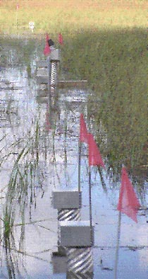
Twenty-one continuous recording, ground-water-level monitor wells were installed along the transect, running about 500 feet both east and west of Levee 30 (figs. 3 and 4). The wells are located in six different clusters where each cluster has two to five wells, with depths ranging from 10 to 80 feet below land surface. Continuous surface-water-level (stage) recorders were also installed along the transect, one in Water Conservation Area 3B and one in the Levee 30 canal. Data are being collected for about 1 year to obtain information for both wet- and dry-season conditions. The data will be used to select boundary conditions for the ground-water flow models and to calibrate the models. Data collection began in June 1995.
Initial data show a significant difference between the stage in WaterConservation Area 3B and the water levels in the Biscayne aquifer, with 1-foot gradients from the conservation area wetlands into the aquifer during periods of extreme high water. This ponding of the surface water is believed to be the result of the thin, impermeable, limestone layer located near the top of the aquifer. Water levels have been above land surface in Water Conservation Area 3B since the installation of the monitor wells. However, Water Conservation Area 3B dries out periodically; this happened, at least in part, most recently in the spring of 1992.
|
| Figure 4 -- Location of wells and stage recorders. |
Discharge measurements are being made in the Levee 30 canal (fig. 5) under various hydrologic conditions at three locations: at the transect, 1 mile south of the transect, and 1 mile north of the transect. The differences in flow rates at these three sections are used to determine the rate at which water is seeping into or out of the canal from the aquifer, a critical input requirement for the ground-water flow models.
|
| Figure 5 -- Discharge measurement in Levee 30 canal. |
A comprehensive report is planned. This report will document the use of selected models for calculating ground-water seepage rates under Levee 30 and present the results from the seepage calculations.
Project ScheduleDates and project activities are summarized below. For those project activities that have not yet begun or have not been completed, tentative dates are given.
By Roy S. Sonenshein
For more information contact:
Caribbean-Florida Water Science Center
U.S. Geological Survey
3321 College Avenue
Davie, FL 33314
Related information:
SOFIA Project: Methods to quantify seepage beneath Levee 30, Miami-Dade County, Florida

![]() U.S. Department of the Interior |
U.S. Geological Survey
U.S. Department of the Interior |
U.S. Geological Survey
URL: http://pubsdata.usgs.gov/pubs/fs/1996/0132/index.html
Page Contact Information: GS Pubs Web Contact
Page Last Modified: Wednesday, 20-Apr-2022 15:58:24 EDT
