1U.S. Geological Survey
P.O. Box 628
Montpelier, VT 05601
Telephone: (802) 828-4528
Fax: (802) 828-4465
e-mail: gwalsh@usgs.gov
2U.S. Geological Survey
National Center MS 926A
Reston, VA 20192
e-mail: jreddy@usgs.gov
tarmstrong@usgs.gov
Field data collection systems have been employed in geologic mapping for several years. Brodaric (1997) described a comprehensive software package called Fieldlog, developed and used by the Geological Survey of Canada. Fieldlog utilizes an Apple Newton Message Pad computer running Fieldworker data collection software. Unfortunately for users of this hardware and software, and for those in the stages of planning an upcoming field season, Apple discontinued the production and support of the Newton in the spring of 1998 so we turned to the burgeoning market of PDA computers. Here we describe the results of our field use of a PDA computer and a GPS receiver for the collection of geologic structure data.
The primary goal of utilizing a GPS receiver and a field data collection system was to address the problem of digitally compiling, in a time efficient manner, numerous geologic structure measurements taken during the course of mapping. The compilation of structure data is often the most time-consuming process in the production of digital geologic maps, especially in areas underlain by complexly deformed and metamorphosed rocks with multiple histories of ductile and brittle deformation. In order to eliminate the need to either spend additional field time entering data on a laptop computer or performing heads-up digitization of drafted and scanned structure symbols in the office, we decided to collect structure data real-time in the field. In order to achieve this goal we needed a highly portable system that would allow, rapid collection of geologic attribute data and positional point data. A secondary goal was to use a data collection system that used popular hardware and software, making it easy for field geologists to learn and customize it to meet their needs.
| Table 1. Items used in the data collection system and the Arc/Info point attribute table (PAT). The description refers to the positional or geologic nature of the item. The source refers to the source of the data either from the GPS waypoint or the Palm III data entry form. | ||
| ITEM: | DESCRIPTION: | SOURCE: |
| STATION | station identifier | numeric keypad |
| POSFMT | GPS position format | waypoint |
| ZONE | GPS utm zone | waypoint |
| HDATUM | GPS horizontal datum | waypoint |
| HRZERR | GPS horizontal error | waypoint |
| ELEV | GPS elevation | waypoint |
| VDATUM | GPS vertical datum | waypoint |
| ELEVUNIT | GPS elevation units | waypoint |
| TYPE | geol. structure (planar, linear, other) | lookup list |
| SUB_TYPE | geol. structure (joint, bedding, etc.) | lookup list |
| STRIKE | geol. structure (0-359 in right-hand rule) | numeric keypad |
| DIP | geol. structure (0-90) | numeric keypad |
| DIPDIR | geol. structure (0-359 in right-hand rule) | numeric keypad |
| REL_AGE | relative age of geol. structure | lookup list |
| SYMBOL | symbol number from Arc/Info markerset | numeric keypad |
| SYMBOL_ANG | Arc/Info symbol rotation value | calculated in Arc/Info |
| ROTATION | relative rotation of geol. structure | lookup list |
| SPACING | spacing of joint sets or fracture zones | numeric keypad |
| WIDTH | width of joint sets or fracture zones | numeric keypad |
| NETSLIP | net slip of small-scale fault | numeric keypad |
| APERTURE | aperture of joints or fractures | numeric keypad |
| MIN1 | primary mineral in vein or fracture | lookup list |
| MIN2 | secondary mineral in vein or fracture | lookup list |
| MIN3 | tertiary mineral in vein or fracture | lookup list |
| CODE | relate item to geologic polygons | freehand text |
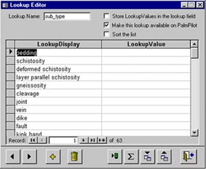
Figure 1. Partial example of a lookup list for the geologic structure item SUB_TYPE. The SUB_TYPE lookup list includes valid data entry values for planar data such as bedding and schistosity shown above, linear data such as fold axes and intersection lineations, and other data such as mines and quarries to name a few. |
Once the forms are complete and they match your data model, you can collect your attribute data and positional waypoint data in the field at every outcrop with the PDA computer and the GPS receiver. The PDA and the GPS need not be physically connected in the field, unlike many data loggers that come as accessories to GPS receivers. This is significant, as it eliminated the need for a connecting wire between the PDA and the GPS, and allowed greater freedom of movement through rugged terrain and dense undergrowth.
After data collection, the PDA and the GPS data are downloaded to a desktop or laptop computer running Microsoft Access and Microsoft Hyperterminal, respectively. Downloads could be completed as often as every day, or as infrequently as once a week depending on access to a computer. We found that access to a laptop in the field office was the most reliable way to ensure adequate backups of the data. Data from the Palm III downloads directly into a Microsoft Access database file, whereas data from the PLGR downloads to an ASCII text file. Positional data from the GPS receiver represent a single point and the attribute data may represent one or many geologic measurements at that point. The attribute data in Access and the positional data in ASCII format are then combined into a single database by establishing a one-to-many relationship in Access using the station and waypoint label as the relate item. After field work is completed, or at any time when a compilation map is desired, the Microsoft Access data can be converted into an Arc/Info point coverage.
The first step in creating the Arc/Info point coverage is to create two separate files from the Access database: 1) an ASCII text file of positional data, and 2) a DBASE IV file of attribute data. This is accomplished by running two select queries in Access and then exporting the two resulting tables to new ASCII and DBASE IV files. In our procedure we name the ASCII file coor.txt and the DBASE IV file attr.dbf. In New Hampshire, we collected GPS data in UTM coordinates so our coordinate file (coor.txt) has three comma-delimited fields: station, east, north. Before exporting, ensure that both files, or select query tables, have the same number of lines and have been sorted by the station field in ascending order. Next add the word "end" as the last line of the coordinate select query table and export the file; the resulting coor.txt file should look like this:
4001,308764,4743207 - first line
4001,308764,4743207
4002,308649,4743384
4002,308649,4743384
...
...
...
6534,312728,4737407
6534,312728,4737407
6534,312750,4737419
end - last line
The format (field size or width and data type, such as numeric or text) of the attr.dbf fields does not have to be explicitly defined in Access or in DBASE because it will be defined when the DBASE file is converted to an INFO file in Arc/Info.
|
Figure 2. Flow chart showing the generalized procedures for collecting and transferring data to an Arc/Info point coverage. |
The generalized procedures for collecting and transferring data to an Arc/Info point coverage are outlined in Figure 2. The generation of the point coverage can be automated by running an Arc/Info macro or AML. The AML (convertdbf.aml) uses the Arc/Info commands DBASEINFO, GENERATE, BUILD, and JOINITEM and is illustrated below:
/***********************************
/* Name: convertdbf.aml
/* Purpose: Converts Palm III PDA and PLGR
/* GPS Access data into an ARC point cover
/* Requires the following files:
/* attr.dbf {DBASE IV format}
/* coor.txt {ASCII format}
/* Usage: &r convertdbf <outcover>
/* Project: USGS New Hampshire
/* Date: September, 1998
/* Authors: Jim Reddy and Greg Walsh
/*
/***********************************
&args cover
/* OPEN TABLES - CHECK FOR
/* EXISTING ATTR.DBF DATA TABLE
tables info
&if [exists attr -info] &then kill attr
quit
/* CONVERT THE ATTR.DBF FILE
/* TO AN INFO DATA TABLE
/* Modify the following definitions to match
/* your ATTR.DBF file and your data model
dbaseinfo attr.dbf attr define
station station 6 6 n 1
posfmt posfmt 8 8 c
zone zone 4 4 c
hdatum hdatum 8 8 c
hrzerr hrzerr 4 4 i
elev elev 5 5 i
vdatum vdatum 8 8 c
elevunit elevunit 2 2 c
type type 10 10 c
sub_type sub_type 35 35 c
strike strike 3 3 i
dip dip 2 2 i
dipdir dipdir 3 3 i
rel_age rel_age 10 10 c
symbol symbol 3 3 i
symbol_ang symbol_ang 3 3 i
rotation rotation 3 3 c
spacing spacing 5 5 c
width width 5 5 c
netslip netslip 5 5 c
aperture aperture 5 5 c
min1 min1 3 3 c
min2 min2 3 3 c
min3 min3 3 3 c
code code 8 8 c
end
/* GENERATE THE POINT COVERAGE
/* FROM THE COOR.TXT INPUT FILE
&if [exists %cover% -cover] &then kill %cover% all
generate %cover%
input coor.txt
points
quit
/* BUILD THE POINT COVERAGE
build %cover% point
/* JOIN THE POINT COVERAGE PAT FILE /* AND THE ATTR DATA TABLE
joinitem %cover%.pat attr %cover%.pat %cover%# %cover%-id link
&return
Once the point coverage is created, SYMBOL values can be checked or added based on values from marker symbols in an Arc/Info markerset of geologic symbols such as those created by Fitzgibbon and Wentworth (1991). Before plotting the symbols in the correct orientation, the item SYMBOL_ANG must first be calculated from STRIKE values for planar symbols and DIPDIR values for linear symbols. This calculation depends largely on the orientation of the symbols in the markerset and the method of collecting strike data. After calculation of the item SYMBOL_ANG, the pseudo item $ANGLE can be calculated as equal to SYMBOL_ANG. The pseudo item $ANGLE records the rotational angle for individual symbols in Arc/Info and is based on a Cartesian coordinate system with East = 0°, North = 90°, West = 180°, and South = 270°. This differs from standard geologic angles where North = 0°, East = 90°, South = 180°, and West = 270°.
In the past, data collection typically involved recording structure data in field notebooks by hand followed by data entry into a computer database or heads-up digitizing of drafted and scanned structure symbols after the completion of field work. The old method often led to lengthy periods of data processing and even simplification of the dataset in order to meet budgetary constraints and deadlines. The Hartland quadrangle in Vermont is underlain by similarly complex geology and the Arc/Info point coverage contains 1600 points (Walsh, 1998). Compilation of the structural geology point coverage took a total of approximately 40 hours and included hand-drafting of symbols with pen and ink on mylar (24 hours), scanning and registering the drafted symbols (1 hour), and heads-up digitizing (15 hours). For comparison, compilation of the point coverage for the Windham, New Hampshire quadrangle required only approximately 10 hours and included periodically downloading GPS and Palm III data (8 hours), data manipulation in Microsoft Access (1 hour), and generation of the Arc/Info point coverage (1 hour). In this comparison, the old method used in Vermont took four times as long to create a point coverage with only two-thirds the number of points.
Fitzgibbon, T.T., and Wentworth, C.M., 1991, ALACARTE User Interface: AML code and demonstration maps, U.S. Geological Survey Open-File Report 91-587.
Johnson, B.R., Brodaric, Boyan, and Raines, G.L., 1998, Draft digital geologic map data model, versions 4.2 and 4.3: Unpublished American Association of State Geologists / U. S. Geological Survey draft document, 83 p., http://ncgmp.usgs.gov/ngmdbproject/.
Walsh, G.J., 1998, Digital bedrock geologic map of the Vermont part of the Hartland quadrangle, Windsor County, Vermont: U.S. Geological Survey Open-File Report 98-123, 17 p., scale 1:24,000.
Walsh, G.J., and Clark, S.F., Jr., 1999, Bedrock geologic map of the Windham quadrangle, Rockingham and Hillsborough Counties, New Hampshire: U.S. Geological Survey Open-File Report 99-8, scale 1:24,000, https://pubs.usgs.gov/openfile/of99-8/.
|
Return to Table of Contents
This site is https://pubs.usgs.gov/openfile/of99-386/walsh.html
|