|
|
|
|
|
|
|
|
|
|
|
|
In 1996, the U.S. Geological Survey (USGS), in cooperation with the U.S. Army Corps of Engineers (USACE), began a program to produce geologic framework maps of the southern Long Island nearshore area (Fig. 1). Our methods include high-resolution sidescan sonar and subbottom profiling techniques (Schwab and others, 1997 and 1999a,b), along with surface and vibracore sampling to verify the geophysical interpretations. The goal of the investigation is to determine regional-scale availability of sand as a resource for beach nourishment programs and to investigate the role that inner-shelf morphology and geologic framework have in the evolution of the coastal region of southern Long Island. Maps derived from interpretation of the subbottom profiles show information on the geometry and distribution of the Quaternary sediments and the underlying Coastal Plain unconformity. This seismic stratigraphy yields a regional framework on which explanations of present (and past) sediment movement, dispersal, and erosion processes are based (Schwab and others, 1999a,b).
Long Island marks the southern boundary of the late Pleistocene glacial advance in the eastern part of North America (Stone and Borns, 1986). Two end moraines are superimposed along the western part of northern Long Island. The moraines bifurcate in eastern Long Island, where each moraine forms the core of peninsulas north and south of Peconic Bay (Fig. 2). The Ronkonkoma moraine on the southern peninsula extends eastward beneath the Atlantic Ocean to Block Island, Marthas Vineyard, and Nantucket.
The topography of Long Island (Fig. 3) exhibits greater relief along the end moraines on the northwestern side, particularly where the two moraines are superimposed. There are gentler, southward dipping gradients where the moraines merge with a related outwash plain. The coast from Southampton to Montauk Point is a headland region where the Ronkonkoma moraine and associated outwash sediment are eroded directly by wave action (Williams, 1976). The south shore of Long Island west of Southampton consists of reworked outwash and includes shallow back-barrier bays, marshes, and low-relief, sandy (fine-to-medium-grained sand) barrier islands (Leatherman and Allen, 1985).
The onshore stratigraphy of Long Island (Table 1) has been mapped from well-log data by Suter and others (1949), Perlmutter and Todd (1965), Soren (1971), and most recently by Smolensky and others (1989). The wells penetrate glacial and interglacial sedimentary deposits, and semiconsolidated Cretaceous sedimentary rock. Some of the deeper wells bottom out in metamorphic bedrock. The bedrock surface slopes southeastward so that maximum depths of the bedrock surface occur beneath the southern Long Island shoreline (~600 m beneath Fire Island).
Semilithified strata of Upper Cretaceous age overlie metamorphic bedrock and have been divided into stratigraphic units (Table 1). The oldest unit, the Raritan Formation, is composed of the Lloyd Sand Member capped by an unnamed clay member. The Raritan Formation is interpreted to have been deposited in a non-marine fluvial environment and comprises a distinct fining upward sequence, from fine to coarse sand and gravel of the Lloyd Sand Member to the silty clay of the unnamed clay member (Smolensky and others, 1989). The Magothy Formation, including undifferentiated deposits of the Matawan Group (Perlmutter and Todd, 1965), lies unconformibly above the Raritan Formation and consist of nonmarine fluvial deposits that grade from a coarse basal zone up to fine sands and clay. The uppermost Monmouth Group lies unconformably over the Matawan Group and Magothy Formation, undifferentiated. This unit is a marine transgressive deposit that is rich in glauconite. It is restricted to the south-central part of Long Island and probably extends southward in the nearshore area of southern Long Island (Perlmutter and Todd, 1965, Smolensky and others, 1989).
A regional unconformity separates the Upper Cretaceous from Quaternary deposits. The Upper Cretaceous has been eroded by glacial processes north of the terminal moraines and by fluvioglacial erosion south of the moraines (Smolensky and others, 1989). The Jameco Gravel is the oldest Pleistocene deposit recognized beneath Long Island. This fluvial coarse-sand and gravel deposit of Illinoian age is restricted to the western part of Long Island. Several interglacial lagoonal and shallow marine clay deposits are found within the Pleistocene unit. The Gardiners Clay, deposited during the Sangamon interglacial (ca. 125 ka), is the most distinct and mappable of these units. The Gardiners Clay is restricted in the subsurface to the south side of Long Island, east of Shinnecock Inlet, and is inferred to extend offshore beneath the nearshore of southern Long Island (Williams, 1976; Smolensky and others, 1989). Upper Pleistocene deposits, consisting of clay, sand, gravel, and boulder till, form the Ronkonkoma and Harbor Hill moraines of Wisconsin age. The associated outwash is comprised of sand-to-boulder deposits south of the moraines. Holocene-age deposits consist of local distributions of salt marsh or lagoonal-organic mud and peat, stream alluvium, and beach deposits (Smolensky and others, 1989).
Williams (1976) completed a high-resolution seismic-reflection profiling survey of southern Long Island to delineate sand and gravel resources. His interpretation of the seismic stratigraphy and correlation with cores, land borings, and exposures identifies four primary seismic units (Table 1). The upper surface of the first unit, crystalline bedrock, was identified in northern Gardiners Bay, but not in the Atlantic intercontinental shelf due to a lack of subbottom penetration. Semi-lithified Upper Cretaceous strata overlie the crystalline bedrock. These strata dip and thicken to the southeast, are present in the shallow subbottom of the inner-continental shelf off southern Long Island, and project northward beneath Long Island. The third seismic stratigraphic unit includes Pleistocene outwash sand and gravel interbedded with interglacial silts. The Pleistocene unit lies above an erosional surface cut by glacial and fluvioglacial erosion into the Upper Cretaceous strata. This boundary is the same regional unconformity that was mapped onshore, informally referred to as the Coastal Plain unconformity. Offshore, the Coastal Plain unconformity is clearly recognized on seismic-reflection profiles as an angular unconformity where Cretaceous Coastal Plain strata are truncated (Williams, 1976). Williams (1976) also mapped a series of paleodrainage channels cut into the Cretaceous strata. The Pleistocene deposits are thicker in the eastern part of the study area where paleochannels are more prevalent. The paleochannels dissect the Coastal Plain surface in a north-south orientation on land and continue south across the inner shelf. The fourth unit comprises Holocene age deposits that were not well defined in seismic profiles collected by Williams (1976), probably due to their limited vertical resolution. However, core samples delineated these offshore Holocene deposits as modern marine sands deposited over organic-rich mud, interpreted by Williams (1976) as typical back-barrier-beach deposits.
The study area extends from the lower shoreface and inner-continental shelf, approximately the 8-m isobath, to about 10 km offshore (Fig.1). The area was surveyed with high-resolution sidescan-sonar, seismic-reflection, bathymetric and sediment sampling techniques in May 1996, aboard the research vessel Seaward Explorer and in May 1997 and September-October 1997 aboard the research vessel Diane G. Details of the sidescan sonar and fathometer acquisition and processing are described by Schwab and others (1999b).
The seismic-reflection data were acquired using a Datasonics 2-7 kHz swept FM Chirp subbottom profiler, a component of the Datasonics SIS-1000 sidescan sonar and Chirp subbottom system, a 300-3000 Hz Geopulse boomer system, a 100-3000 Hz single-electrode sparker, a multi-electrode sparker, and a 200 kHz fathometer. Ship tracklines (Fig. 4), parallel to shore, were spaced with an average line spacing of 300 m to provide continuous sidescan-sonar coverage of the sea floor. Shore perpendicular tie lines were spaced 4 to 5 km apart.
Ship position was determined from a Differential Global Positioning System (DGPS). The sidescan sonar and Chirp subbottom fish was navigated relative to the ship using an acoustic-ranging system. The position of the towfish was calculated assuming that the towfish was directly behind the research vessel; i.e., that it followed the ship trackline. This assumption is relatively accurate when the research vessel was running in straight line, with a small amount of tow cable deployed; however, because the towfish position error increases in turns by 10's of meters, data collected during turns were generally discarded. We estimate that the positions of the bathymetric data, seismic-reflection data, sample locations, and sidescan-sonar imagery are accurate to within 5 m. This estimate is verified from the good fit of features when matching adjacent sidescan-sonar lines in the mosaicing process.
All of the seismic-reflection data were acquired in digital format. The Chirp subbottom data were logged on a Triton ISIS system in QMIPS format as a third channel with the sidescan-sonar data. The Chirp subbottom channel was extracted from the QMIPS data and converted to single-channel SEG-Y standard format (Barry and others, 1975) using an in-house C program (QMIPSTOSEGY). In the conversion process, the number of Chirp traces was decimated by a factor of two (keeping every other trace). The acoustic-range-corrected DGPS coordinates and towfish depths from a towfish-mounted pressure transducer were written to the SEG-Y trace headers for use in data processing. Most of the Chirp data were acquired at a 1/4-second fire rate (this translates to a horizontal distance of 4 meters between traces because of trace decimation and an average ship speed of 5 knots) and sweep lengths, except for some 1/8-second fire rate data off Fire Island. The boomer and sparker data were recorded in SEG-Y standard format (Barry and others, 1975) on a USGS seismic acquisition system (MUDSEIS). The boomer and sparker were usually acquired at 1/2-second fire rate (this translates to a horizontal distance of 4 meters between traces assuming an average ship speed of 5 knots) and sweep lengths. All of the SEG-Y data were archived onboard ship on CD-ROM.
The Chirp, boomer, and sparker SEG-Y data were processed using Landmark Graphics Corp. (LGC) Promax seismic processing software. Automatic gain control (AGC) with a 10-ms window was applied to the Chirp data. Chirp data from 1997 were smoothed (51 point moving average applied to fish depth values before static correction) to compensate for sea-surface roughness from vessel and towfish heave. Boomer and sparker data were processed by applying a zero-phase Butterworth band-pass filter (325-2400 Hz) followed by a time-varying (T˛) gain. All of the processed Chirp data and some of the processed boomer and sparker data were exported to LGC Seisworks seismic interpretation software.
The seismic-trace data imported into Seisworks from Promax were merged with shot-point navigation within Seisworks, and seismic-reflection horizons were interpreted and digitized. All of the available Chirp data were utilized. Boomer and sparker data included all shore-perpendicular tie lines; shore-parallel lines spaced approximately 1000-2000 meters apart were included. Thickness between horizons (assuming a seismic velocity of 1630 m/s) was calculated, and the Universal Transverse Mercator (UTM) zone 18 easting and northing coordinates with unit thickness were exported from Seisworks. The thickness data were imported to Dynamic Graphics, Inc. (DGI) Earthvision surface modeling software for gridding and contouring. Topographic and bathymetric coastal elevation models (Pratson and others, 1999; Sharman and others, 1999; http://www.ngdc.noaa.gov/mgg/coastal/coastal.html) were used as a base for surface models of Quaternary sediment thickness and depth to the Coastal Plain unconformity. Land-based well-log data were digitized (Lotto, 1999) from a series of maps and well logs produced by the New York State Department of Conservation and the USGS in 1949. The original maps were part of a groundwater resources study based on 2158 well logs on Long Island (Suter and others, 1949). These were combined with nearshore data to obtain a continuous model of the land and nearshore framework. Grids and images of gridded data from Earthvision were exported to ESRI ArcView mapping software before exporting to CorelDraw for drafting.
The seismic stratigraphy from this study defines four main units: Cretaceous Coastal Plain deposits, Pleistocene glacial and fluvioglacial deposits, and Holocene reworked marine sand deposits. The fourth unit consists of deposits filling an intricate paleochannel system cut into the upper Pleistocene surface. The paleochannel fill consists of Pleistocene to Early Holocene fluvial deposits, Holocene tidal-inlet deposits, or Holocene estuarine sediments. All four units are exposed in places at the sea floor and can be identified on sidescan-sonar imagery (Schwab and others, 1999a,b). A regional unconformity, the Coastal Plain unconformity, separates the Upper Cretaceous strata from the overlying Quaternary deposits.
Coastal Plain Strata and Coastal Plain Unconformity
Strong and continuous internal reflectors identify the Cretaceous Coastal Plain strata on the boomer and sparker profiles. These strata dip and thicken to the southeast along the entire length of Long Island (Williams, 1976). Reflectors west of Shinnecock Inlet have a higher gradient (as much as 12 m/km) than to the east. The Coastal Plain unconformity defines the upper boundary of Coastal Plain strata in subbottom profiles (Fig. 5). The elevation of this unconformity is mapped throughout the study area (Fig. 4). This boundary forms a distinct angular unconformity west of Shinnecock Inlet where dipping Coastal Plain strata are truncated and buried by Pleistocene deposits (Fig. 5a). East of Shinnecock Inlet, the Coastal Plain unconformity is less distinct or not resolved on the subbottom profiles due to its relatively low angle to the Coastal Plain strata. The first strong and continuous regional reflection on the boomer and sparker subbottom profiles defines the unconformity in this area (Fig. 5b).
The elevation of the Coastal Plain unconformity (Fig. 4) was mapped by modeling the surface of the Upper Cretaceous using onshore well data (Suter and others, 1949) and the offshore Coastal Plain unconformity observed in boomer and sparker subbottom profile data. In the western part of the study area, where the Quaternary deposits are relatively thin, the unconformity can be mapped from Chirp profiles. The elevation on land and in the nearshore region is relatively high west of Fire Island Inlet. This is consistent with the Coastal Plain cuesta mapped by Williams (1976). Elevation of the Coastal Plain unconformity deepens gradually to the east of Fire Island Inlet to Montauk Point except for a series of local highs. At one local high, 6 miles offshore of Watch Hill, the Coastal Plain strata are exposed at the sea floor as confirmed in both sidescan-sonar imagery and subbottom profiles (Schwab and others, 1999a). Other local highs on the Coastal Plain unconformity occur in the subsurface along the southern shoreline between Great South Bay and South Hampton, and east of Napeague to Montauk Point.
Thickness and Distribution of Quaternary Sediment
The total Quaternary sediment thickness shown in Figure 6 includes Pleistocene-age glacial or fluvioglacial deposits as well as Early Holocene age paleochannel fill and modern marine deposits: all sedimentary deposits above the Coastal Plain unconformity. The isopach map (Fig. 6) shows that deposits are thickest on land (maximum of 165 m) along the Harbor Hill and Ronkonkoma Moraines and in a relatively deep depression in the Coastal Plain surface beneath Shelter Island. West of Fire Island Inlet, Quaternary deposits are thin (a few meters) on land, south of the moraine, and in the nearshore where the Coastal Plain surface elevation is relatively high. East of Fire Island Inlet, glacial outwash thins to the south from the Ronkonkoma Moraine to a relatively uniform thickness in the nearshore area. However, the deposit thickens to >30 m in the area offshore of Watch Hill extending south to the Coastal Plain outcrop offshore and in the nearshore area between Shinnecock Inlet and Napeague. Further east, towards Montauk Point, Quaternary deposits are locally thicker where paleochannels are cut into the Coastal Plain strata. The localized thickening near Watch Hill may originate from a wedge of outwash built up north of the Coastal Plain outcrop offshore. As much as 6 meters of modern marine sand located north and west of the Coastal Plain outcrop contribute to thickening of Pleistocene deposits. The area of thickening in the Southampton to East Hampton area is apparently because of the offshore extension of outwash deposits (Fig. 6). This thickening is coincident with the extent of a reflector that has been identified within the Pleistocene unit on seismic profiles (Fig. 5b). The southern extent of this reflector and the Pleistocene outwash unit above it occurs as much as 9 km offshore of Shinnecock Inlet where it crops out at ~30 m water depth.
Thickness and Distribution of Paleochannel Fill
There is an extensive, complex paleochannel system developed on the surface of the glacial and fluvioglacial deposits over most of the study area (Fig. 7). The paleodrainage system resulted from downcutting into glacial deposits during the Late Pleistocene or Early Holocene. The paleochannel deposits are fluvial or fluvioglacial at the channel base and may be capped by Holocene estuarine deposits. An 8000-year-old peat was sampled in a paleochannel ~5 km offshore of the present shoreline of the Shinnecock area (R. Thieler, U.S. Geological Survey, personal communication). The channels appear to occur at the same stratigraphic level, although many of the channels exhibit a complex or nested internal cut-and-fill structure. There is great variability within a given region - the channel shape can be sharply incised, U-shaped, or flat-based (Fig. 8a). Some channel systems are exposed at the sea floor and others are covered by modern (reworked) sand. Some channels bifurcate, others coalesce, and others extend as a single axial feature. Their basal depth varies. Some channels appear to be only partially preserved due to erosion at the sea floor. Other well-preserved channels are cut down to the Coastal Plain unconformity (Fig. 8a), particularly in the western part of the study area where glacial deposits are relatively thin (Fig. 6). The seismic expression, amplitude and waveform varies even within channels of similar shape and depth. West of the Cretaceous outcrop, off Watch Hill, the channels are better developed and preserved. In the intermediate area off Shinnecock, they are extensively eroded and the majority are only preserved close to shore in water depths Ł ~18m. The preservation of paleochannels may also be constrained, in part, by the steeper slope of the nearshore in the eastern part of the study area.
Thickness and Distribution of Modern Sand
The modern marine sand unit appears acoustically amorphous on the Chirp profiles and lies unconformably over Pleistocene glacial deposits and relict Holocene-age channel-fill deposits (Fig. 8b). We interpret this unconformity to represent the Holocene transgressive or ravinement surface. Note that the term "modern" describes the relative age of the deposit that overlies the time-transgressive Holocene ravinement surface. The modern sand deposits are fine grained, well sorted, and are thought to be highly mobile (Schwab and others, 1999a,b). The isopach map (Fig. 9) of the modern marine sand unit shows a series of sand ridges along the southern nearshore area. Between the ridges the modern sand is either too thin to be resolved in the Chirp data, or is absent. Interpretations of subbottom, sidescan-sonar, and multibeam bathymetric data suggest that large areas of the sea floor consist of Pleistocene or Early Holocene deposits. West of the Watch Hill area, the modern sand ridges are oriented at angles of 30°- 40° to the shoreline, opening to the east and are attached to or are proximal to the shoreface. This series of sand ridges is up to 7 m thick immediately west of the outcropping Cretaceous strata off Watch Hill. They become progressively thinner farther westward and are less than 1 m thick off Fire Island Inlet. The sand ridges appear as areas of relatively low backscatter on sidescan-sonar imagery, whereas areas between the ridges are relatively high in backscatter. Surface samples and USACE vibracores show that the ridges are composed of very-well-to-moderately-sorted, and medium-to-very fine-grained sand (Schwab, 1999a,b). Two additional sets of modern sand ridges, also oriented at angles of 30°- 40° to the shoreline, are located east of Watch Hill. However, these sand ridges are located seaward of the 18-m isobath and thus are not attached to the shoreface. Sand in one set of ridges reaches a maximum thickness of 3 m off Shinnecock Inlet and thins to the west. Sand in another set of sand ridges is a maximum of 3 m thick south of Montauk Point and also thins to the west. Finally, sand below a modern shoal up to 12 m thick occurs southeast of Montauk Point. Surface samples show that sand in both sets of ridges and the shoal are texturally similar to the sand in ridges west of Watch Hill (Schwab and others, 1999a,b).
The sand in shore-attached ridges along western Fire Island was derived from a thickened glacial deposit shoreward of the Cretaceous outcrop. The sand thins progressively westward in the direction of predominant longshore transport. These ridges may be considered an analog to similar ridges located 5 to10 km offshore Shinnecock Inlet that might have been active along a former shoreline (Schwab and others, 1999a,b).
The high-resolution seismic stratigraphy derived from Chirp, boomer, and sparker subbottom profiling and a dense survey grid provides a detailed shallow framework of the southern Long Island nearshore. The stratigraphic framework together with sidescan-sonar imagery (Schwab and others, 1997and 1999a,b) constitutes a detailed data set from which the depositional history of the area can be interpreted.
The upper surface of the Cretaceous (Coastal Plain unconformity) forms the foundation for the overlying blanket of Quaternary sediments. The Cretaceous strata crop out and form a local bathymetric high off Watch Hill. This local high appears to have influenced the thickness of Pleistocene deposits shoreward of the Cretaceous outcrop. This area is interpreted by Schwab and others (1999a,b) as a former headland, similar to the present day headland bluffs of Southampton, and as sea level rose, it provided a source of sand that contributed to the formation of western Fire Island and the modern shoreface-attached sand ridges.
Pleistocene glacial deposits form a relatively uniform deposit over most of the study area. The deposit is only absent at the Cretaceous outcrop off Watch Hill. Local thickening occurs off the coastal bluffs of Southampton and in channels cut into the Cretaceous.
A system of paleochannels is cut into the Pleistocene deposits. The continuity and strong basal reflectors of these channels suggest they are fluvial or fluvioglacial in origin. Most cores indicate a transgressive sequence in which channel fill is capped with estuarine mud (Unpublished USGS and USACE core data). Some of the discontinuous paleochannels could be tidal-inlet paleochannels, but the strong continuity of the paleodrainage pattern (Fig. 7) suggests most paleochannels are fluvial in origin. Determining the depositional environment of the channels will require more ground-truth information such as extensive coring.
Modern Holocene sand deposits, derived from reworking of the Pleistocene glacial deposits, partially cover older deposits and form a series of shore-attached and -detached sand ridges. The distribution of modern sand deposits is consistent with patterns on sidescan-sonar imagery and multibeam bathymetry.
[an error occurred while processing this directive]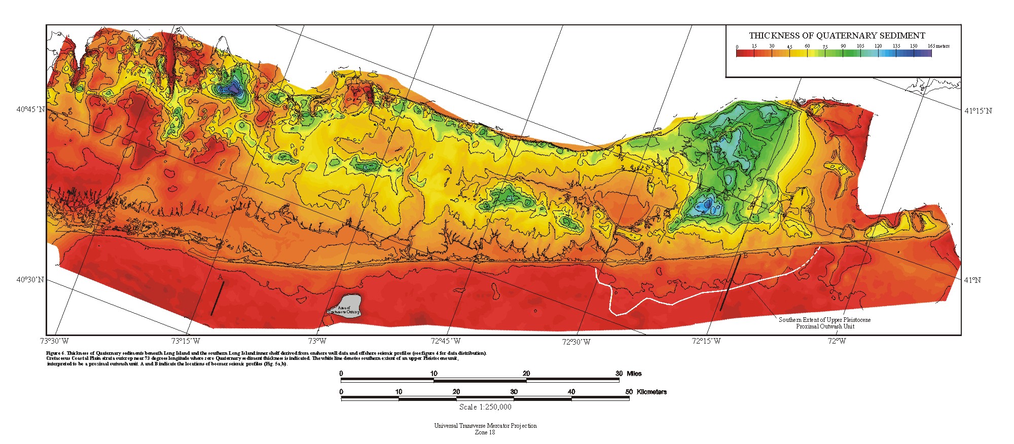