
Digital Mapping Techniques '04— Workshop Proceedings
U.S. Geological Survey Open-File
Report 2004–1451
Migrating from ArcInfo Workstation to ArcGIS
Natural Resources Canada, 601 Booth Street, Ottawa, Ontario, Canada K1A 0E8; Telephone: (613) 943-2693; Fax: (613) 952-7308; e-mail: vdohar@NRCan.gc.caINTRODUCTION
During the past ten years, geological maps at the Geological Survey of Canada (GSC) have been produced using ESRI’s ArcInfo Workstation software along with a custom application called GEMS (GEological Mapping System – available at http://www.nrcan.gc.ca/ess/carto/toolbox_e.html). Supporting this application in delivering high-quality publications, Cartographic Digital Standards and Cartographic Design Specifications are used to manage the spatial data and surround elements that appear on the map, respectively.
With the recent introduction of ArcGIS and the benefits that this new technology offers, considerable re-tooling of the process will be required to achieve the product quality that we achieved with ArcInfo Workstation. This will cover all aspects of production, from data management to developing and implementing new applications. From a cartographic perspective, this document will explain the migration strategies for developing a geodatabase design to manage the data, as well as some ideas for producing maps with ArcMap. The content of this document is based on the ESRI product ArcGIS 8.3. General knowledge of ArcGIS, particularly geodatabase elements and design, will be beneficial.
MIGRATING TO ArcGIS
Goals
One of our main goals is to be able to produce geological maps with ArcMap as effectively and efficiently as with ArcInfo Workstation. The majority of this effort has involved designing a geodatabase schema to store and manage the geological features that constitute a map. The geodatabase also provides the means for feature-validation through the use of domains for standardizing feature names and user-defined topologies. Domains can be used to restrain the user in assigning values to an attribute field from an established list of coded values or a numeric range. Topologies will ensure users adhere to the established spatial relationships between features.
Another goal is to keep the design of the geodatabase simple and easy to understand. This will be achieved by eliminating unnecessary data fields, using intuitive and obvious field names, implementing the use of domains, and using tables and defined relationships where necessary.
Migration Strategy
The gradual migration from ArcInfo to ArcGIS can be characterized as occurring in three stages. These are outlined in ESRI’s help documentation, and are summarized below:
In our migration strategy, we decided to merge steps 1 and 2, delivering both at the same time. The primary reason for this approach is to eliminate the transition phase that could affect our service delivery of map products. Using two software suites to produce maps and manage data could potentially create bottlenecks, and data management and versioning issues that could affect the timely delivery of map products (both paper and digital). In addition, based on past experiences, it will be easier to train everyone at the same time to make the transition.
DESIGNING A GEODATABASE
A geodatabase contains the geographic or spatial features and their attributes, which can be used to produce a geological map. Geographic features of a homogenous theme and spatial type (e.g., contacts, which are lines) are stored in feature classes. Feature classes that are physically related to one another (e.g., contacts, faults, and geological polygon units) are best to be grouped in a feature dataset. This grouping permits the application of user-defined topological rules that express the relationships between each of the feature classes. The feature name, definitions, attribute fields, and properties of these feature classes determine the schema or design used in the geodatabase. There are three basic methods in designing a geodatabase schema:
Designing a Geodatabase for Map Production
Our map products are either bedrock or surficial maps, and so we decided to tailor the design of geodatabases to this type of information. Therefore, separate geodatabases will be created for bedrock and surficial geological datasets. This may seem redundant, but there are areas where both thematic features have been mapped, either on different maps or on one map. Storing the data in separate geodatabases will provide a better means for managing the data as well as referencing it when making maps with ArcMap. Some of the criteria we will use for creating a geodatabase schema are as follows:
Managing Geological Polygons and Legend Information
At this time, much of the effort at GSC has involved implementing a surficial geological geodatabase; however, there will be many aspects applicable to a bedrock geological geodatabase. In the design of a surficial geodatabase schema, the first feature we examined was the geological polygons. The surficial map sample from ArcMap (Figure 1) displays one of the methods authors from the GSC use to classify geological polygons. Many of the surficial geological polygons are labeled on the map with one or two units, where each unit is listed and described separately in the legend. These compound units (e.g. “Cv/Tm”) can consist of veneers (in this case, “Cv”) overlying a dominant unit (“Tm”) or as a proportional mix between two geological units (Tx/R). In most cases, veneers include the lowercase character “v”, and for compound units, a symbol is used between the two geological units to express the type of relationship and ratio of each unit. These methods are intended as a visual aid for the map-reader, but a different approach is required to better manage this type of information and structure in a geodatabase.
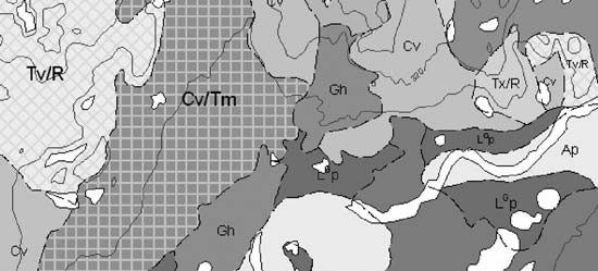 |
Figure 1. Sample black and white image of a colour surficial map from ArcMap. |
The values assigned to the geological polygons, including the relationship information for these compound units, is stored in the attribute field MAPUNIT, in the polygon feature class table (Figure 2). The values do not necessarily have to match the polygon label on the map. In fact, they can be any value, string or numeric, as the value relates to another table that describes the composition of each unique polygon value as well as the label to be placed on the map.
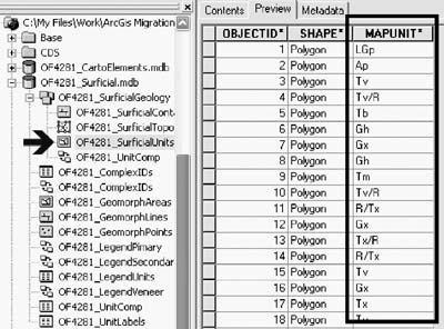 |
Figure 2. Snap shot from ArcCatalog. The left-hand side displays the catalogue tree, with the arrow pointing to the currently selected polygon feature class “OF4281_SurficialUnits”. The attributes of these features are displayed on the right-hand side. The bold outline contains the attribute values of each feature in the MAPUNIT field. |
The table UnitComp (Figure 3) is used to describe the composition of each unique polygon value. In this table, a field also named MAPUNIT contains all the unique polygon values from the above polygon feature class. Three additional fields are used to define the composition. The VENEER field contains geological units that are classified as veneers. The PRIMARY_UNIT and SECONDARY_UNIT fields contain geological units that are classified as the primary and secondary units respectively. The values in these three fields relate directly to the geological units that appear in the legend.
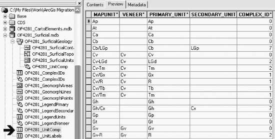 |
Figure 3. Snap shot from ArcCatalog. The arrow is pointing to the currently selected table “OF4281_UnitComp”, which is displayed to the right. This table contains all unique polygon values in the field MAPUNIT. Subsequent fields further define the composition of each unique polygon value and the nature of the composition. |
A fourth field named COMPLEX_ID is used to identify the relationship or proportional mix between each of the geological units in a composition as defined by the author. The integer values in this field relate to the ComplexIDs table (Figure 4), where each type of relationship or complex ID is explained. On the map, symbols such as · (middle dot), - (dash), / (slash), and // (double slash) are used as visual aids to express these relationships (e.g., the middle dot between two units is used to express a 50/50 proportional mix between a primary and secondary unit).
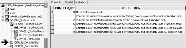 |
Figure 4. Snap shot from ArcCatalog. The arrow is pointing to the currently selected table “OF4281_ComplexIDs”, which is displayed to the right. This table lists the different types of relationships for geological units that participate in a composition. |
Another table, called LegendUnits (Figure 5) contains all the geological units that appear on the legend and provide the definitions for all surficial geologic units listed in the UnitComp table. In the LegendUnits table, each geological unit contains a description, as well as heading information (not shown in figure) that would appear on the legend (e.g., Glacial Till).
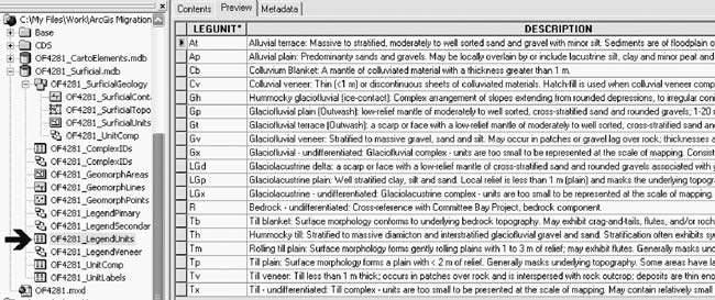 |
Figure 5. Snap shot from ArcCatalog. The arrow is pointing to the currently selected table “OF4281_LegendUnits”, which is displayed to the right. This table contains each geological unit and its description as it appears in the legend on the map. |
The final table associated with geological polygons is used for dynamically labeling the polygons in ArcMap. This table, called UnitLabels (Figure 6), also contains all unique polygon values for the field MAPUNIT found in the above polygon feature class. The field MAPLABEL contains the text string that will be used by ArcMap to label the polygons. Using this kind of table ensures consistency and allows the use of text formatting tags to show unit labels with superscript, subscript, bold, and coloured type (see text formatting tags in ArcMap Help for more information). In the example map in Figure 1, the geological unit LGP contains a superscript character (the superscript G for this unit was requested by the author for this particular map). The field MAPUNIT is defined as a text field and cannot contain any superscript or special characters, therefore the value “LGP” is used for these types of polygons. The field MAPLABEL, also defined as a text field, contains the superscript formatting tags to achieve the superscript character when labeling (circled in Figure 6).
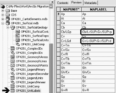 |
Figure 6. Snap shot from ArcCatalog. The arrow is pointing to the currently selected table “OF4281_UnitLabels”, which is displayed to the right. This table is used in ArcMap for dynamically labeling polygons. The field MAPLABEL is used as the label text field for each unique polygon. The bold outline displays two examples of using text-formatting tags, in this case to achieve the superscript character. |
In order to use this table in ArcMap for labeling, an ArcMap relate must be specified between the layer (polygons) and the table. A relationship class (discussed below) is not necessary, as this table is only used for labeling purposes, and not used for querying the polygon and legend information. Furthermore, when labeling polygons in ArcMap, classifications can be created based on the area of the polygons being labeled to achieve different point sizes for the labeled text strings. For example, small polygons (area ≤ 10,000 m2), medium polygons (area > 10,000 m2 and ≤ 100,000 m2), and large polygons (area > 100,000 m2) can be labeled with 8, 10, and 12 pt. type respectively. As with all GIS software, the labels are arbitrarily placed, and therefore further cartographic refinement is required. The labels can be converted to annotation and their placement adjusted to provide a more legible map. At this time, we are unsure if this table and/or the use of relates in ArcMap can be used in advanced labeling engines like the MAPLEX extension.
For data analysis and map production, these many tables must be related by creating relationship classes. A relationship class defines which fields are related between tables, as well as the nature of the relate. A total of five relates exist, each defined as a separate relationship class. Figure 7 shows the table and field names, and their relationships. You can see the relationship classes in the previous figures, preceded by an icon (two small boxes with arrows pointing to each other in the catalogue tree). These tables and relationship classes exist in the geodatabase, but they could also exist in the feature dataset containing the SurficialGeology polygon feature class to which they are related. Storing them at either location is acceptable, but it would have been better in these examples, from a file management perspective, to store the tables and relationship classes in the SurficialGeology feature dataset.
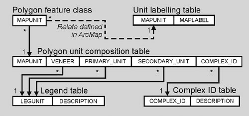 |
Figure 7. Diagram showing the relationship between the fields in the tables. Each line is defined as a relationship class in the geodatabase. Cardinality is expressed as 1 (one) and * (many). |
Creating relationship classes will allow end-users to query information from ArcMap (at this point it is unsure if this can also be achieved with ArcIMS, ArcReader, or ArcExplorer). By selecting a polygon, the end-user can display the attributes from all of the tables by navigating through the established relates (Figure 8).
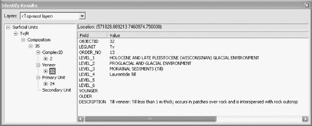 |
Figure 8. ArcMap snap shot displaying results of an identify procedure on a selected feature. The left-hand side displays the tables in a tree format as one migrates from the selected feature, through the established relates to other tables (just as confusing as it appears). The right-hand side displays the attributes of the geological unit “Tv” from the legend table. For this selected feature, the geological unit “Tv” also participates in a composition as a veneer with the map unit “Tv/R”. |
Managing Geological Line, Point, and Other Area Features
Our current plan for managing all other surficial geological line, point, and area features on a geological map is to store them in separate, stand-alone feature classes. In the surficial geodatabase schema discussed above, these would be the feature classes GeomorphLines, GeomorphPoints, and GeomorphAreas. These feature classes would also incorporate the use of sub-types and domains to assist in categorizing and validating the features.
Domains are a property of the geodatabase, and as such can be applied to any feature class. In fact, the domains created for these features will be generic to all geodatabases. Domains are used to constrain values for a field, and can include acceptable coded values or a numeric range. In most cases, coded value domains are used to specify each type of geological feature, and numeric range domains are applied where numeric fields are used to store attribute information, such as the strike (rotation) and dip of a geological symbol. Domains are used in all custom fields in a feature class; thus validating a feature class will ensure that the attribute values of all features are acceptable and valid. In the following example (Figure 9), the Glacial domain has been created as a coded value domain that lists valid values and their descriptions.
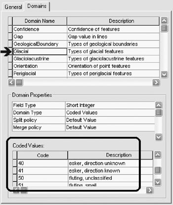 |
Figure 9. Snap shot from ArcCatalog displaying the domains as a property of the geodatabase. The arrow is pointing to the “Glacial” domain with valid coded values and descriptions shown below in the bold outline. |
Sub-types provide a means for categorizing or grouping features within a feature class by assigning unique values to a long-integer defined field. In the example below (Figure 10), the polygon feature class has a sub-type field named CATEGORY, with two valid values: 1 (to store glacial features), and 2 (to store glaciolacustrine features). Sub-types allow for different domains to be applied to each sub-type classification. For example, for the glacial and glaciolacustrine feature sub-types, the field FEATURE will only accept coded values from the Glacial and Glaciolacustrine domains respectively. This is highly useful, because each sub-type classification can have its own unique attribute values, which are specified by the domain. Furthermore, these domains can be applied to more than one feature class. Depending on the compilation scale, features can be stored either as points, lines, and/or areas in the respective feature classes (GeomorphPoints, GeomorphLines, GeomorphAreas). For example, drumlins are usually stored as point or line features. In both feature classes they would exist in the sub-type Glacial, and the Glacial domain would apply to the field FEATURE. Therefore, these features must be coded as “drumlin” based on the coded value from the Glacial domain, regardless of the type of feature.
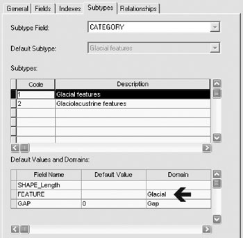 |
Figure 10. Snap shot from ArcCatalog displaying the sub-types as a property of a feature class. Highlighted is the “Glacial features” subtype, in which case values for the field FEATURE must adhere to the “Glacial” coded value domain. |
User-defined Topologies
In addition to feature validation, another benefit of geodatabases is the ability to create custom topologies based on feature classes that exist in a feature dataset. Custom topology involves specifying which feature classes will be participating, the relationship rules between the features, and the cluster tolerance (similar to the fuzzy tolerance from ArcInfo Workstation). For our application, user-defined topologies apply only to the geological polygons datasets, where the SurficialContacts and SurficialUnits feature classes participate. The two rules that are implemented are:
The second rule simply states that the contact lines must coincide with the outline of the polygons. The rule could have been expressed the other way around: the outlines of polygons must overlie the contact lines, but this would have caused excessive topological dirty areas (errors) where contact lines do not exist (i.e., at the edges of bodies of water which close some polygons).
MAKING MAPS WITH ARCMAP
Style Files and Symbols
Unfortunately, customized symbolsets from ArcInfo Workstation cannot be used directly or imported into ArcMap. This has required a significant investment of time, to rebuild the libraries for approximately 400 line and 700 point symbols. The majority of the time has been spent creating TrueType fonts containing the point symbols, using third-party software (Font Lab and Fontographer). Our current set of symbols/style files for ArcMap are available free of charge from our “Migration to ArcMap” website (http://www2.nrcan-rncan.gc.ca/ess/carto/arcgis_e.asp).
Using XML for Map Surrounds and Legends
During the past ten years of producing geological maps using ArcInfo Workstation, several customized commands have been developed to assist cartographers in placing surround information (title blocks, legends, logos, credits, descriptive notes, recommended citation, figures, etc…). Unfortunately, these commands are all written in AML (Arc Macro Language), and as such cannot be used to position these elements, or to aid in the layout of a map using ArcMap. In order to provide the same level of functionality, scripts will have to be written using VBA (Visual Basic for Applications) and ArcObjects. In addition, the information associated to each of the surround elements will be stored in XML. The source of this information will either be obtained from existing metadata or inputted by the cartographer. Storing this information in XML will not only assist in the placement of these surround elements, but the XML file can be used by third parties to extract the information about the map they require. This effort is currently being developed, and is not yet incorporated in the production of maps with ArcMap.
Another aspect of the map surround information is the geological legend. These legends, created using ArcInfo Workstation, also rely on AML programming. A similar approach will also be taken in producing legends using ArcMap, utilizing XML to store content derived from the legend tables. Much of this work is just beginning.
ACKNOWLEDGMENTS
I wish to acknowledge the efforts of Roger MacLeod and Parm Dhesi, in migrating the ArcInfo symbolsets to style files; Norah Brown for her expertise in ArcObjects programming and XML; and Sheila Hynes, Barb Szlavko, and Terry Houlahan for their support and expertise in geodatabase, SDE, and Oracle administration.
REFERENCES
ESRI Inc., 1999–2002, ArcGIS Desktop Help 8.3: ESRI Inc.
ESRI Inc., 2003, Geodatabase Designer Help: ESRI Inc. (developed by the Applications Prototype Lab).
ESRI Inc., 2003, Geodatabase Case Studies: ESRI Inc., Geodatabase Case Studies, Chapter 9 Topography and the Base Map (draft publication).
Fontlab software is available from Fontlab Ltd., Inc., accessed at http://www.fontlab.com/.
Fontographer software is available from Macromedia, Inc., accessed at http://www.macromedia.com/software/fontographer/.