U.S. Geological Survey Open-File Report 2005-1428
Digital Mapping Techniques '05—Workshop Proceedings
1Colorado State University/National Park Service Cooperator,
1201 Oak Ridge Drive, Suite 200,
Fort Collins, CO 80525
Telephone: (970) 225-3584;
e-mail: Stephanie_O’Meara@partner.nps.gov; Heather_Stanton@partner.nps.gov; Jim_Chappell@partner.nps.gov
2National Park Service Pacific West Region, Seattle Office e-mail: Greg_Mack@nps.gov
3United States Forest Service Chippewa National Forest e-mail: apoole@fs.fed.us
4University of Denver/National Park Service Cooperator e-mail: Georgia_Hybels@partner.nps.gov
Geologic maps are an integral component of the physical science inventories stipulated by the National Park Service (NPS) in its Natural Resources Inventory and Monitoring (I&M) Guideline. The NPS has identified Geographic Information Systems (GIS) and digital cartographic products as fundamental resource management tools. There are few geologists employed at parks, thus these tools are particularly important to the NPS to aid resource managers in using geologic data for park management decisions (OMeara et. al., 2003).
The NPS Geologic Resources Division (GRD) is currently developing a Geologic Resources Evaluation (GRE) that includes a geologic bibliography, a summary report of each parks geologic resources, and the development of a geology-GIS data model for implementation in the production of digital geologic-GIS data for each park. Colorado State University is a partner in the development and production of these products.
The present NPS Geology-GIS Data Model (OMeara et. al., 2005a) for park digital geologic-GIS data is based upon Environment Systems Research Institute (ESRI) ArcInfo coverage and shapefile vector file formats and provides a robust method for storing geologic data. Recently, ESRI developed the geodatabase format for storing spatial data within a relational database management system (RDBMS). A geodatabase stores data in point, line or polygon data layers (feature classes) that can be grouped into a feature dataset, a logical groupings of vector feature classes that share the same spatial extent. The geodatabase has the added strength of allowing attribute validation rules, relationship classes, and topological rules that maintain data integrity within and between feature classes.
In order to take advantage of this new, enhanced functionality, migration from the coverage/shapefile-based geology-GIS data model to a geodatabase geology-GIS data model is underway. Using geologic data from Glacier National Park, Montana (GLAC), our poster presented at this meeting outlines 1) the present NPS Geology-GIS coverage/shapefile data model, and its benefits and drawbacks, 2) the ESRI geodatabase architecture and key components, and 3) the implementation of the NPS Geology-GIS Data Model within the geodatabase architecture, and its benefits and drawbacks. The Glacier National Park, Montana (GLAC) digital geologic-GIS map was produced from existing published USGS paper maps (Whipple, 1992 and Carrara, 1990). Of note, Figures 1 through 6 and 10 in this paper were produced using Microsoft Office Visio objects created from Geodatabase Diagrammer, an ArcScript created by ESRI.
The present data model defines how geologic features are captured, grouped and attributed in coverage and shapefile formats. In addition, relationships with ancillary source map and geologic unit information tables are also established in the data model. Acceptable data model data layer attribution values, or domain lists, are stored in separate table files.
In the existing coverage/shapefile data model (OMeara et. al., 2005a), geologic features are currently divided into 30 coverages and 38 shapefiles. The discordance in the corresponding number of files between coverages and shapefiles is the result of the capability of the coverage format to store multiple geometries within one coverage file. Shapefiles do not support multiple geometries and therefore multiple files are needed to represent some features. Table 1 lists coverage/shapefile data model data layers by geologic feature and spatial type (i.e. polygon, line and point).
| Geologic Features | Coverage Abbreviation (Spatial Type) |
Shapefile Abbreviation (Spatial Type) |
|---|---|---|
Geologic Units and Contacts |
GLG (polygon and line) | GLG (polygon) and GLGA (line) |
| Linear Geologic Units | GLN (line) | GLN (line) |
| Point Geologic Units | GPT (point) | GPT (point) |
| Faults | FLT (line) | FLT (line) |
| Folds | FLD (line) | FLD (line) |
| Attitude Observation Localities | ATD (point) | ATD (point) |
| Age-Date Localities | DAT (point) | DAT (point) |
| Volcanic Line Features | VLN (line) | VLN (line) |
| Volcanic Point Features | VPT (point) | VPT (point) |
| Linear Dike Units | DKE (line) | DKE (line) |
| Area Dike Swarms and Contacts | DKS (polygon and line) | DKS (polygon) and DKSA (line) |
| Mine Point Features | MIN (point) | MIN (point) |
| Cross Section Lines | SEC (line) | SEC (line) |
| Area Volcanic Units and Contacts | ASH (polygon and line) | ASH (polygon) and ASHA (line) |
| Metamorphic/Alteration Boundaries | MET (line) | MET |
| Linear Glacial Features | MOR (line) | MOR (line) |
| Structure Contour Lines and Other Lines | LN# (line) | LN# (line) |
| Joints | JLN (line) | JLN (line) |
| Sensitive Geologic Point Features SPF | SPF (point) | SPF (point) |
| Unique Geologic Point Features | UPF (point) | UPF (point) |
| Surficial Units and Contacts | SUR (polygon and line) | SUR (polygon) and SURA (line) |
| Measured Unit Thickness Localities | MUT (point) | MUT (point) |
| Mine Area Features | MAF (polygon and line) | MAF (polygon) and MAFA (line) |
| Seismic Data Localities | SMC (point) | SMC (point) |
| Sample Localities | SAM (point) | SAM (point) |
| Area Deformation Zones | DEF (polygon and line) | DEF (polygon) and DEFA (line) |
| Geologic Hazard Line Features | HZL (line) | HZL (line) |
| Geologic Hazard Point Features | HZP (point) | HZP (point) |
| Glacial Area Features | AGF (polygon and line) | AGF (polygon) and AGFA (line) |
| Geologic Hazard Area Features | HZA (polygon and line) | HZA (polygon) and HZAA (line) |
Coverage and shapefile feature attribute tables consist of descriptive attribute fields that contain information about geologic features in the data model. Attribute field parameters include field name, data type, field definition, and field width parameters. Figure 1 presents the attribute table for the Geologic Units (GLG) coverage/shapefile data layer.
Figure 1. Geologic Units (GLG) coverage/shapefile data layer attribute table. Attribute table fields highlighted in white store information about geologic unit polygons (areas) such as: geologic feature identification number (GLG_IDX); geologic unit symbol (GLG_SYM); source map geologic unit symbol (USGS_SYM); an age number sorting units from youngest to oldest (GLG_AGE_NO); a source map ID number (GMAP_ID); and a variable used to link a geologic unit to a map help file containing geologic unit descriptions (HELP_ID). Standard ArcInfo polygon attribute fields are highlighted in medium gray. These are created automatically, and include area (AREA), perimeter (PERIMETER), a unique internal feature ID (GLACGLG#), and a unique internal ID (GLACGLG-ID).
Several benefits exist for a coverage/shapefile-based data model. These include:
Several drawbacks also exist for the coverage/shapefile-based data model. These include:
A geodatabase stores spatial and non-spatial data, including attributes, in tables, feature classes, and feature datasets. In addition, the geodatabase stores attribute validation rules, relationship classes, and topological rules for ensuring data integrity.
Two types of geodatabases exist: personal and multi-user (enterprise). Personal geodatabase support is implemented in ArcGIS using the Microsoft Jet Database Engine and is suitable for project-level GIS. Enterprise databases are deployed using ArcSDE and require a DBMS such as IBM DB2, Informix, Oracle, or Microsoft SQL Server. The NPS geodatabase data model presented here was constructed in a personal geodatabase.
Similar to the coverage/shapefile data model, the proposed NPS Geology-GIS Geodatabase Data Model (OMeara et. al., 2005b) includes a list of feature classes, and feature attribute tables. More importantly the geodatabase data model also includes: 1) a geodatabase relational schema, 2) domains, 3) subtypes, 4) topological rules, and 5) relationship classes.
Geologic features are currently divided into 44 geodatabase feature classes. Table 2 lists these feature classes by geologic feature type and spatial type (i.e. polygon, line and point).
| Geologic Features | Feature Class Abbreviation | Spatial Type |
|---|---|---|
| Geologic Units | GLG | polygon |
| Geologic Contacts | GLGA | line |
| Linear Geologic Units | GLN | line |
| Point Geologic Units | GPT | point |
| Surficial Units | SUR | polygon |
| Surficial Contacts | SURA | line |
| Volcanic Ash Units | ASH | polygon |
| Volcanic Ash Contacts | ASHA | line |
| Linear Dike Units | DKE | line |
| Dike Swarm Units | DKS | polygon |
| Dike Swarm Contacts | DKSA | line |
| Deformation Zones | DEF | polygon |
| Deformation Zone Boundaries | DEFA | line |
| Faults | FLT | line |
| Folds | FLD | line |
| Linear Joints | JLN | line |
| Attitude Observation Localities | ATD | point |
| Geologic Sample Localities | GSL | point |
| Cross Section Lines | SEC | line |
| Structure Contour Lines and Other Value Lines | CN# | line |
| Observation, and Observed Extent and Trend Lines | LIN | line |
| Volcanic Linear Features | VLF | line |
| Volcanic Point Features | VPF | point |
| Geologic Linear Features | GLF | line |
| Geologic Point Features | GPF | point |
| Glacial Area Features | GAF | polygon |
| Glacial Area Feature Boundaries | GAFA | line |
| Glacial Linear Features | GFL | line |
| Glacial Point Features | GFP | point |
| Mine Area Features | MAF | polygon |
| Mine Area Feature Boundaries | MAFA | line |
| Mine Point Features | MIN | point |
| Geologic Hazard Area Features | HZA | polygon |
| Geologic Hazard Area Feature Boundaries | HZAA | line |
| Geologic Hazard Linear Features | HZL | line |
| Geologic Hazard Point Features | HZP | point |
| Alteration and Metamorphic Areas | AMA | polygon |
| Alteration and Metamorphic Area Boundaries | AMAA | line |
| Alteration and Metamorphic Linear Features | AML | line |
| Alteration and Metamorphic Point Features | AMP | point |
| Geologic Measurements Localities | GML | point |
| Seismic Localities | SMC | point |
| Geologic Observation Localities | GOL | point |
| Map Symbology | SYM | point |
In the NPS Geology-GIS Geodatabase Data Model, feature classes representing each of the geologic data layers on a single map are grouped into a feature dataset. All feature classes that participate in the feature dataset share the same spatial reference (i.e., projection and datum). Feature datasets store spatial data and relationships, but do not store tables. Tables are stored within the geodatabase, but outside the feature dataset. Feature datasets are necessary to the creation of topological rules, which will be discussed later. Figure 2 presents the geodatabase data model schematic for the Digital Geologic Map of Glacier National Park, Montana (GLAC), which includes the maps feature dataset and related ancillary tables.
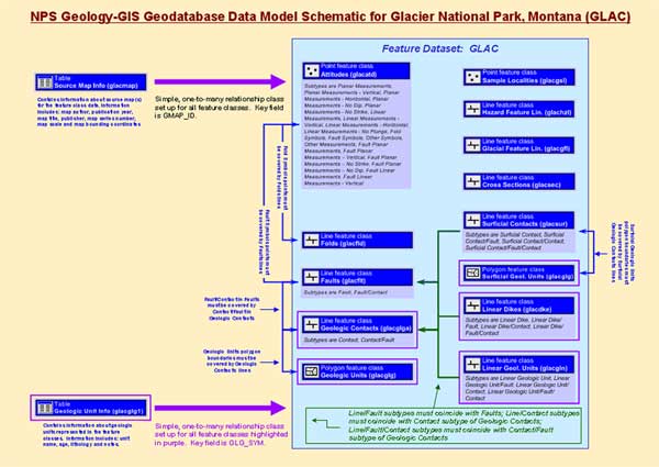
Figure 2. Geodatabase data model schematic for the Digital Geologic Map of Glacier National Park, Montana (GLAC) showing map feature dataset, feature classes, ancillary map tables, and implemented relationship classes.
Feature attribute tables in the geodatabase consist of descriptive attribute fields that contain information about the features within a feature class. Attribute field parameters include field name, data type, whether or not to allow null values, field definition, domain type (coded value or range), and field width (precision, scale and length). Figure 3 presents the attribute table for the Geologic Units (GLG) feature class.
Figure 3. Geologic Units (GLG) feature class attribute table. Attribute table fields highlighted in white store information about geologic unit polygons (areas) such as: geologic unit symbol (GLG_SYM); source map geologic unit symbol (SRC_SYM); a notes and remarks field (NOTE); a source map ID number (GMAP_ID); and a variable (HELP_ID) used to link a geologic unit to a map help file containing geologic unit descriptions. Attribute fields highlighted in medium gray are created automatically in a geodatabase, and include a unique feature ID (OBJECTID), as well as geometry type (SHAPE), length (SHAPE_Length), and area (SHAPE_Area).
Attribute domains define acceptable values for fields in attribute tables that are contained in the geodatabase. Coded value domains are used in the NPS Geology-GIS Geodatabase Data Model to define acceptable values for various feature class type fields and their subtypes (see Subtypes section) including: Attitude Type (subtypes planar measurements, linear measurements, etc.), geologic contact type, fault type, and fold type. Range domains are used to define ranges of acceptable values for attribute fields such as strike, dip, and rotation in the Attitude Observation Localities (ATD) feature class. By placing limits and definitions on acceptable values, domains help to ensure consistency when attributing the features. Figure 4 presents the coded value domain used to define acceptable values for horizontal planar measurements (planar horizontal values subtype) in the Attitude Observation Localities (ATD) feature class. Figure 5 presents a range domain defining acceptable values for attitude strike/trend values for numerous subtypes in the Attitude Observation Localities (ATD) feature class.
 |
 |
Figure 4. Coded value domain used to define acceptable values for the planar horizontal measurements subtype in the Attitude Observation Localities (ATD) feature class. All acceptable coded domain values and their description are listed for the subtype. |
Figure 5. Range domain defining acceptable values for attitude strike for numerous subtypes in the Attitude Observation Localities (ATD) feature class. Acceptable strike/ trend values or azimuths are between 0 and 359 degrees, and are defined in a range domain by a minimum value (0) and maximum value (359). |
Geodatabase subtypes are used to subdivide data in feature classes into groups that share the same attribute or topological validation rules and/or default values. Subtypes are defined by integer values stored in a field in a feature classs attribute table.
The purpose of the contact and contact/fault subtypes in the Geologic Contacts (GLGA) feature class (Figure 6) is to enforce topological rules and attribute validation. For example, the fault/contact subtype in the Faults (FLT) feature class must spatially coincide with the contact/fault subtype in the Geologic Contacts (GLGA) feature class (see Topology section). Subtypes in the Geologic Contacts (GLGA) feature class share the same domain for positional accuracy (CNT_POS).
Nineteen subtypes were created for topological rule enforcement and to control attribution for attitude type, attitude strike/trend, and attitude dip/plunge in the Attitude Observation Locality (ATD) feature class. For instance, the planar measurements subtype consists of planar measurements that have an azimuth (strike) that as a range from 0 to 359 degrees and are inclined at an angle from 0 to 89 degrees. Both measurement values, strike and dip, are restricted by range domains. Another subtype, planar vertical measurements, shares the same strike domain, from 0 to 359 degrees, however, the dip value is restricted by a coded domain to 90 degrees. Figure 7 presents an example of the Attitude Observation Localities (ATD) feature class attribute table.
Figure 6. Geologic Contacts (GLGA) feature class subtypes. Note that the subtype field (GLGA_SUB) is defined as a short integer field. In the attribute table, the subtype description text, in this case contact and faulted contact, appears in the actual attribute table, and not the actual coded value, 0 for contact and 1 for faulted contact. Subtype descriptions appear by default when viewing attribute data and aid in attribution during object creation.
Figure 7. Attitude Observation Localities (ATD) feature class attribute table showing attribute fields with coded domains for attitude observation type, attitude subtype, and positional accuracy fields, and ranges domains for strike/trend and dip/plunge fields. The pull-down list displays attitude type values (ATD_TYPE field) dependent on the subtype field (ATD_SUB), in this case attitude type values that are fault symbols.
In a geodatabase, topological rules govern spatial relationships within and between different feature classes. In the NPS Geology-GIS Geodatabase Data Model, topological rules are used to ensure that: faults exactly coincide with geologic contacts where a fault is also a contact; geologic contacts coincide with the boundaries of geologic units; and fold symbols and fault symbols lie along folds and faults, respectively. Topological rules also stipulate that no gaps or overlaps and no self-intersections do not occur in the various polygon and line feature classes in the geodatabase. Figure 8 illustrates an example of a topology rule error caused by incorrect attribution. Figure 9 presents topology rules for the Glacier National Park, Montana digital geologic-GIS map.
Figure 8. Snapshot of the Glacier National Park, Montana (GLAC) digital geologic-GIS map in ArcMap showing, in gray, a line segment where the rule Must Be Covered By Feature Class Of has been broken. Here, a fault/contact in the Faults (FLT) is covered by a contact in the Geologic Contacts (GLGA). To correct the topological error, the contact should be attributed in the GLGA feature class as a contact/fault.
Figure 9. Topological rules for the Glacier National Park, Montana (GLAC) digital geologic-GIS map are represented with the source or origin feature classes in rows and the destination feature classes in columns. Letters indicate the type of topology rule, as presented right of the principal table. A number before a letter (a topology rule) indicates the subtype in the origin feature class to which the topology rule is applicable. A number following a number (origin feature class) and letter (a topology rule) indicates the subtype of the destination feature class to which the topology rule is applicable. For instance, the Faults (FLT) feature class (source) is related to the Geologic Contacts (GLGA) feature class (destination) using the rule 1-A-1, where the first 1 is the fault/contact subtype (see line subtypes below figure) of the Faults (FLT) feature class, the A represents the topological rule (see list right of table), and the second 1 is the contact/fault subtype of the Geologic Contacts (GLGA) feature class. In other words, a fault/contact in FLT must coincide with a contact/fault in GLGA. If there is no number to represent a subtype for the source and/or destination feature class, the rule applies to the entire source and/or destination feature class. Note that one or more rules may apply to a given source and destination feature class.
Relationship classes store information about how geodatabase objects such as tables and feature classes are interrelated. In the NPS Geology-GIS Geodatabase Data Model, they are used to relate the table of Geologic Unit Information (GLG1) to the Geologic Units (GLG) feature class, as well as to other feature classes containing geologic unit information. They are also used to relate the Source Map Information (MAP) table to all of the feature classes in the geodatabase. See Figure 2 for an example of implemented relationship classes for the Glacier National Park, Montana (GLAC) digital geologic-GIS map.
Relationships are implemented with simple, one-to-many relationship classes, where records in the tables exist independently from feature class objects, as opposed to composite relationship classes where the records in the source table control the deletion/addition of destination feature class objects. For instance, if a composite relationship existed between the Geologic Unit Information (GLG1) table and the Geologic Units (GLG) feature class, with the GLG1 table defined as the source, and the GLG feature class defined as the destination, if a record in GLG1 (source) table was deleted, all related records (in this case actual features) in the GLG (destination) feature class would automatically be deleted as well. Figure 10 displays a relationship between the Geologic Units (GLG) feature class and the Geologic Unit Information (GLG1) table.
Figure 10. A relationship class relating the Geologic Unit Information (GLG1) table to the Geologic Units (GLG) feature class. The field relating the Geologic Unit Information (GLG1) table to the Geologic Units (GLG) feature class is the geologic unit symbol (GLG_SYM) field. Through the relationship, data from all other fields in the Geologic Unit Information (GLG1) table can be accessed, preventing duplication and data redundancy throughout the database.
Several benefits exist for a geodatabase-based data model. These include:
A few drawbacks also exist for the geodatabase-based data model. These include:
Because geologic features present on a geologic map frequently vary, a flexible approach to data model implementation using XML files for each feature class or two interdependent feature classes (i.e., Geologic Contacts (GLG) and Geologic Units (GLGA)) has been adopted. For example, not all geologic maps have faults. Having the functionality to implement a feature class to store faults only if these features are present decreases time spent creating the data layer if needed; including specifying attribute field parameters, domains, and participating relationship classes, and eliminates the need to delete components of a geodatabase that only pertain to a faults data layer should these not be desired in the final digital map.
Methods for implementing topological rules and relationship classes are currently under development. XML files are in the format accepted by Geodatabase Designer version 2, an ArcScript created by ESRI. Figure 11 shows a screen capture of Geodatabase Designer in ArcCatalog.
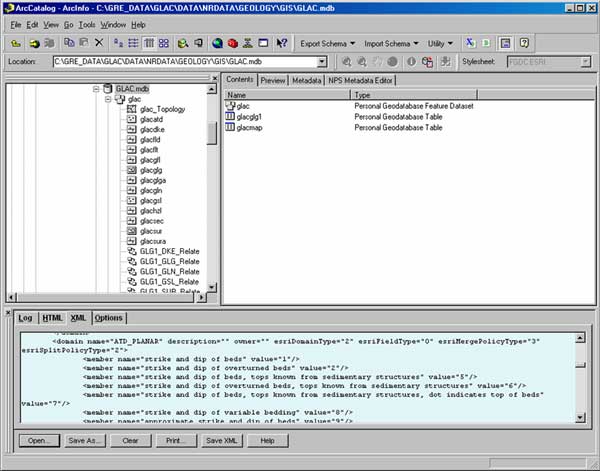
Figure 11. Screen capture of the Geodatabase Designer in ArcCatalog. The Geodatabase Designer is used to implement geodatabase feature class schema stored in XML files. A feature class XML schema file includes name and alias of the feature class(es), as well as field parameters, subtypes, and associated domains. XML schema for the Attitude Observation Localities (ATD) feature class is visible in the lower window of the figure. The schema is implemented in the Glacier National Park, Montana (GLAC) digital geologic-GIS map.
The current NPS Geology-GIS Coverage/Shapefile Data Model provides a robust method for storing geologic map data in a GIS. ESRIs new geodatabase model offers features and functionality that enhance the quality, portability, and scalability of digital geologic map data. The decision to migrate to a geodatabase-based data model was influenced by the potential value that these new features and functionality could bring to the Geologic Resources Evaluations (GRE) digital geologic map data program. The new NPS Geology-GIS Geodatabase Data Model incorporates the functionality of a geodatabase and enhances attribution and data integrity through the use of domains, subtypes, topology, and relationship classes. Current data formats (i.e., coverage and shapefile) also can be supported through export functionality included with ArcGIS.
The GRE program has identified several ideas to further develop, implement, and integrate a geodatabase-based data model into the production of digital geologic-GIS maps. These include:
OMeara, Stephanie, Joe Gregson, Anne Poole, Greg Mack, Heather Stanton and Jim Chappell, 2005a, National Park Service Geologic Resources Evaluation Geology-GIS Coverage/Shapefile Data Model, http://science.nature.nps.gov/im/inventory/geology/GeologyGISDataModel.htm.
OMeara, Stephanie A., Heather I. Stanton, James Chappell, Greg Mack, Anne R. Poole and Georgia Hybels, 2005b, National Park Service Geologic Resources Evaluation Geology-GIS Geodatabase Data Model (Draft v. 1.2), http://science.nature.nps.gov/im/inventory/geology/GeologyGISDataModel.htm.
OMeara, Stephanie A., Trista L. Thornberry, Anne R. Poole, and Victor deWolfe, 2003, The National Park Service Geologic Resources Inventory From Paper to Digital: Exploring a Geologic-GIS Map, in D.R. Soller, ed., Digital Mapping Techniques 03Workshop Proceedings: U.S. Geological Survey Open-File Report 03-471, p. 247-254, available at http://pubs.usgs.gov/of/2003/of03 471/omeara/index.html.
Environmental Systems Research Institute (ESRI) Inc, 2002, Building a Geodatabase: ESRI Inc., 380 New York St., Redlands, CA 92373, http://www.esri.com.
Whipple, James W., 1992, Geologic Map of Glacier National Park, Montana: U.S. Geological Survey Miscellaneous Investigations Series Map I-1508-F, scale 1:100,000.
Carrara, Paul E., 1990, Surficial Geologic Map of Glacier National Park, Montana: U.S. Geological Survey Miscellaneous Investigations Series Map I-1508-D, scale 1:100,000.
ArcGIS 8.3 and 9.0 (ArcCatalog and ArcMap) - Environmental Systems Research Institute (ESRI) Inc., 380 New York St., Redlands, CA92373, http://www.esri.com.
Geodatabase Diagrammer Developed by Michael Zeiler, Environmental Systems Research Institute (ESRI) Inc., 380 New York St., Redlands, CA 92373, http:// arcscripts.esri.com.
Geodatabase Designer v2 Developed by Richie Carmichael, Environmental Systems Research Institute (ESRI) Inc., 380 New York St., Redlands, CA 92373, http:// arcscripts.esri.com.
Microsoft Office Visio Professional 2003, Microsoft Corporation, http://www.microsoft.com.

![]() U.S. Department of the Interior |
U.S. Geological Survey
U.S. Department of the Interior |
U.S. Geological Survey
URL: pubsdata.usgs.gov /pubs/of/2005/1428/omeara/index.html
Page Contact Information: David R. Soller
Page Last Modified: Saturday, 12-Jan-2013 22:05:07 EST
