 |
|
|
A Laboratory Manual for X-Ray Powder Diffraction

| Table of Contents | Introduction | Methods | Clay Minerals | Flow Diagrams |
X-rays are electromagnetic radiation similar to light, but with a much shorter wavelength. They are
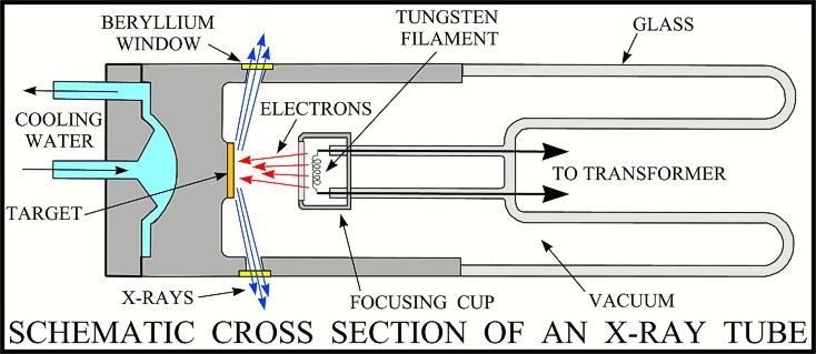 produced when electrically charged particles of sufficient energy are decelerated. In an X-ray tube, the high voltage maintained across the electrodes draws electrons toward a metal target (the anode). X-rays are produced at the point of impact, and radiate in all directions. Tubes with copper targets, which produce their strongest characteristic radiation
(K
produced when electrically charged particles of sufficient energy are decelerated. In an X-ray tube, the high voltage maintained across the electrodes draws electrons toward a metal target (the anode). X-rays are produced at the point of impact, and radiate in all directions. Tubes with copper targets, which produce their strongest characteristic radiation
(K![]() 1) at a wavelength of about 1.5 angstroms, are commonly used for geological applications.
1) at a wavelength of about 1.5 angstroms, are commonly used for geological applications.
If an incident X-ray beam encounters a crystal lattice, general scattering occurs.
 Although most scattering interferes with itself and is eliminated (destructive interference), diffraction occurs when scattering in a certain direction is in phase with scattered rays from other atomic planes. Under this condition the reflections combine to form new
 enhanced wave fronts that mutually reinforce each other (constructive interference). The relation by which diffraction occurs is known as the Bragg law or equation. Because each crystalline material has a characteristic atomic structure, it will diffract X-rays in a unique characteristic pattern.
 The basic geometry of an X-ray diffractometer involves a source of monochromatic radiation and an X-ray detector situated on the circumference of a graduated circle centered on the powder specimen. Divergent slits, located between the X-ray source and the specimen, and divergent slits, located between the specimen and the detector, limit scattered (non-diffracted) radiation, reduce background noise, and collimate the radiation. The detector and specimen holder are mechanically coupled with a goniometer so that a rotation of the detector through 2x degrees occurs in conjunction with the rotation of the specimen through x degrees, a fixed 2:1 ratio.
A curved-crystal monochromator containing a graphite crystal is normally used to ensure that the detected radiation is monochromatic. When positioned properly just in front of the detector, only the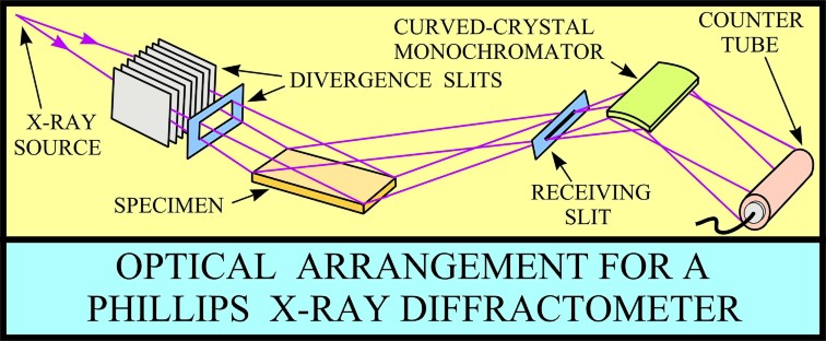 K
K![]() radiation is directed into the detector, and the Kß radiation, because it is diffracted at a slightly different angle, is directed away. The signals from the detector are filtered by pulse-height analysis, scaled to measurable proportions, and sent to a linear ratemeter for conversion into a continuous current. Common output devices include strip-chart recorders, printers, and computer monitors.
radiation is directed into the detector, and the Kß radiation, because it is diffracted at a slightly different angle, is directed away. The signals from the detector are filtered by pulse-height analysis, scaled to measurable proportions, and sent to a linear ratemeter for conversion into a continuous current. Common output devices include strip-chart recorders, printers, and computer monitors.
Selected Bibliography
[an error occurred while processing this directive]