Digital Mapping Techniques '03
— Workshop Proceedings
U.S. Geological Survey Open-File
Report 03–471
Geologic Map Database Implementation in the ESRITM Geodatabase Environment
Arizona Geological Survey, 416 W. Congress # 100, Tucson, AZ 85701
Telephone (520) 770-3500; fax (520) 770-3305; email Steve.Richard@azgs.az.gov
Introduction
The Arizona Geological Survey (AZGS) has been producing 1:24,000-scale geologic map deliverables for the National Cooperative Geologic Mapping Program since the inception of the program. Digital compilation and production of map deliverables started on a prototype basis in 1998, using ArcEdit for map digitizing, and ArcView 3.2 for cartographic production. Map layouts were converted into Adobe Acrobat documents, and are available on CDROM or as hard copy generated using an HP 755CM large-format inkjet printer. The release of version 8.3 of ArcGIS, with the capability of enforcing topological relationships between geologic lines (faults and contacts) and polygons, makes it possible to do the entire map compilation and production process in one software environment. Digital compilation and cartography is done by the mapping geologists at the AZGS, and the ability to do all map production work in one software environment means the geologists need only learn one software package. In order to reduce the amount of software training necessary, we decided to convert to map production using ArcGIS 8.3, and in 2002–2003 produced 7 quadrangle-map deliverables using this product.
AZGS geologic map databases have been produced with spatial data in ArcInfo coverages and with thematic data (mostly metadata, so far) in Microsoft Access databases. The ESRI Geodatabase data model used in ArcGIS 8.3 allows implementation of an integrated database containing both spatial data and thematic data in one package. ArcGIS 8.3 introduced a new model for representing topologic relationships between geologic contacts and faults and the polygons representing outcrop of geologic units. The new software release also added some subtype and domain definition functionality. Production of geologic maps using the new software allowed us to investigate these capabilities for improved geologic map representation.
DATABASE CONCEPTUAL DESIGN
The data structure described here builds on the design described in Richard and Orr (2001), and is intended to conform to the conceptual model produced by the Data Model Design Team of the North American Data Model Steering Committee (NADMSC, 2003) (http://nadm-geo.org/).
GEODATABASE IMPLEMENTATION
The geologic map database implementation consists of a feature dataset (see table 1) that contains geologic points, lines, and polygons feature classes; a feature dataset for cross-sections; a feature dataset for cartographic objects in the map layout that have fill symbols corresponding to geologic units (map explanation, correlation of map units); and a group of tables containing thematic data. The AZGS implementation uses personal geodatabases, which are Microsoft Access .mdb files.
| Table 1. Definition of selected ESRI geodatabase terms. | |
|
Term
|
Definition
|
|---|---|
|
Feature dataset
|
A collection of related feature classes, all of which share a common spatial
reference system.
|
|
Feature class
|
A collection of spatial objects
with their attributes.
|
|
Topology
|
A collection of rules concerning spatial relationships between feature classes
in a single feature dataset.
|
|
Spatial reference
|
Specification of a coordinate system, spatial domain (minimum and maximum X,
Y, and Z coordinates), and precision.
|
|
Subtype
|
Subset of data instances in a feature class or table, differentiated by integer
values in a database field of that class or table.
|
The geologic spatial data is in a feature dataset named GeologyFeatures. The spatial reference for the geology feature dataset was defined using a standard spatial reference system designed for the state of Arizona, with meters as the unit of measurement (Table 2). The coordinate system provides better than 1 millimeter (mm) possible precision for horizontal coordinates (see scale value in Table 2, 1/1533.9 m), which is considered quite adequate given that location uncertainty assigned to mapped geologic contacts by AZGS geologists is generally no better than 10 m.
| Table 2. Spatial domain for Arizona (meters). | |||
|
Coordinate
|
Min
|
Max
|
Scale
|
|---|---|---|---|
|
X
|
-200000.0
|
1200000.0
|
1533.92
|
|
Y
|
3000000.
|
4400000
|
1533.92
|
|
Z
|
-50000
|
10000
|
35791.39
|
The GeologyFeatures dataset contains a point feature class, line feature class and polygon feature class; and one topology. Points represent stations occupied in the field; they may be associated with one or more structural measurements, samples, photos, rock descriptions, etc. The line feature class represents contacts (depositional, gradational, intrusive. . .) and faults, and the polygon feature class represents outcrop of geologic map units on the map horizon depicted. User-defined fields for the line and polygon geology feature classes are identical to those described in Richard and Orr (2001). The table associated with point locations has been modified from the GeoPnt table described in Richard and Orr (2001) using feedback from AZGS geologists. The Station data feature class attributes (Table 3) are designed to accommodate all standard data collected in the field. Multiple instances of this class may share the same location, and contain different information ‘bits’ collected at that site. One topology is defined with the lines and polygons participating. Rules for this topology are summarized in table 4. These rules implement the same topology implemented in an ESRI polygon coverage.
| Table 3. Fields for station data feature class | |
|
Name
|
Description
|
|---|---|
|
OBJECTID
|
Long Integer, Internal geodatabase field. Unique identifier for each station
record feature. In personal geodatabase, this is a Microsoft Access autonumber
field.
|
|
Shape
|
Internal geodatabase field. Representation of feature geometry.
|
|
DataSetID
|
Long Integer. Unique identifier for this dataset (object class in geodatabase
parlance). Analogous to ID field in GDB_ObjectClasses table in geodatabase
.mdb file. Because the ObjectClass interface does not allow the user
to assign object class or data set identifies, these must be maintained
externally (AZGS DataSetAz table, see Richard and Orr (2001)).
|
|
STATION
|
Text, width 32. Field geologist’s unique identifier for station. Multiple station
records may be associated.
|
|
GROUPING
|
Text, width 64. Text string that may be used to group data observations. Example:
group measurement records for a foliation orientation and a lineation
orientation measurement for which the foliation contains the lineation
to form a compound fabric. Informal field for use by field geologist.
|
|
HEADING
|
Text, width 32. Text string that the geologist may use to classify data observations
to facilitate analysis. For instance, geologist may have informal map
unit designations, or an alternate system of classifying structural data
(S1, S2, S3. . .). Informal field for use by field geologist.
|
|
DESCRIPTION
|
Text, width 255. Text description of a geologic feature at the station. The Grouping
and Heading fields allow the geologist to break up and classify notes
taken at a station into different records according to the topic. For
instance lithology descriptions might all be in records with a header
like ‘lithology’, and alteration descriptions might all have a heading
‘alteration’. Informal field for use by
field geologist.
|
|
STRIKE
|
Decimal number. Azimuth or bearing of orientation measurement, from north, in
degrees. For surfaces, use right-hand rulečwhen facing in azimuth direction,
surface dips to the right. For overturned surfaces, the dip value is
reported >90, and the strike azimuth is reported in the direction for which the surface
is tilted down on the right, through vertical to attain overturned disposition.
For directed linear features, such as mylonitic lineation with known
sense of shear, azimuth is reported in positive direction, and plunge
(dip) is <0 if the positive direction is up-plunge. Domain: −360 < Strike < 360.
|
|
ERR_STRIKE
|
Decimal number. Angular uncertainty in determination of orientation azimuth;
for example orientation = Strike ± Err_strike. Analogous to alpha95
value in spherical statistics. Domain 0 < Err_strike < 180.
|
|
DIP
|
Decimal number. Plunge of linear feature or dip of planar feature. May be >90 for overturned surfaces, or <0 for directed linear features that have an up-plunge positive direction. Domain
−90 < Dip < 360.
|
|
SAMPLE
|
Text, width 24. Geologist’s identifier for rock sample collected at station.
Informal field for use by field geologist.
|
|
ANALYTICAL
|
Text, width 24. Sample collection purpose, if sample collected for analysis.
Informal field for use by field geologist.
|
|
Label
|
Text, width 24. Text string for labeling the point location. Examples: dip or
plunge value to display with structure symbol, or Sample identifier string.
|
|
TYPE
|
Text, width 24. Text string, name of concept specified by {TypeID, TypeDS}. This
is redundant, but provided for ease of use by geologists. Domain: Names
of concepts in dataset(s) specified by TypeDS field value.
|
|
TypeID/TypeDS
|
Compound foreign key, link to classification concept that identifies the kind
of of station data recorded in this record. May be notes, sample, unclassified,
structural measurement, etc. For structural data, identifies the kind
of structure orientation data described. It is a foreign key that joins
to the ConceptID field of the
ClassificationConcept table.
|
|
SYMBOL
|
Text, width 24. Text string, name of symbol specified by {CartoObjID/CartoObjDS}.
This is redundant, but provided for ease of use by geologists. Domain:
Names of symbols in dataset(s) specified by CartoObjDS field value.
|
|
CartoObjID/CartoObjDS
|
Compound foreign key, link to the symbol used to depict a feature in the default
map visualization. It is a foreign key that joins to the CartoObjID field
of the CartographicObject table.
|
|
ROTATION
|
Decimal number. Rotation value for oriented structure symbol, specified using
ArcView 3.2 rotation conventions (mathematical convention)č0 is due east,
positive rotation is counterclockwise.
|
|
UTME
|
Decimal number. UTM easting coordinate for station location. Duplicates information
contained in shape field, but provided for transportability to other
GIS software.
|
|
UTMN
|
Decimal number. UTM northing coordinate for station location. Duplicates information
contained in shape field, but provided for transportability to other
GIS software.
|
|
ACCURACY
|
Decimal number. The spatial uncertainty in the location of a feature, in meters.
For example, a value of 10 for a point feature indicates that the geologic
entity represented by the point is within 10 meters of the reported coordinates.
Domain: >0.
|
|
mapHorizon
|
Text, width 128. Text string identifying the surface (generally earth surface)
upon which the mapped outcrop traces are located. This can be thought
of as a proxy for Z (elevation) values for features.
|
|
TrackingNotes
|
Notes on origin of feature; used during dataset construction to build complete
tracking record
identified by {TrackingID, TrackingDS} link.
|
|
TrackingID/TrackingDS
|
Compound foreign key, link to the origin tracking (metadata)
for each object. It is a foreign key that joins to the TrackingID field
of the
TrackingRecord table.
|
| Table 4. Topology rules for geologic lines and polygons | |
|
1.
|
Lines may not intersect.
|
|
2.
|
Lines may not have dangles.
|
|
3.
|
Polygon boundaries must have coincident geologic lines.
|
|
4.
|
Polygons must not overlap.
|
|
5.
|
Polygon may not have gaps.
|
Subtypes
The geodatabase data model allows one field in a table or feature class to be specified as a subtype field. The field must contain integer values. This allows subsets of a feature class to have distinct value domains defined for database fields, and to have distinct topology rules. The subtype hierarchy is only one level deep, and only one hierarchy may be represented. The subtype values must be entered by hand in a dialog, along with any description of the subtype (fig. 1).
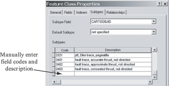 |
Figure 1. Subtype definition dialog. CartoObjID codes are those defined by AZGS. |
Several fields might be used as a subtype field for geologic lines (table 5). After consideration of the pros and cons, the CartoObjID field (symbolization selector field) was chosen to define subtypes. This has proven very useful in several ways. During data entry, the symbol is selected before digitizing a feature, and is immediately displayed on screen using standard geologic symbolization (defined using a standard legend file). The selected symbol provides constraints on data that may be entered in other fields. For instance, selection of a solid line implies a maximum value for the Accuracy field, depending on the map accuracy standard. The symbol also implies one or a few possible ConceptID values; if a thrust fault symbol subtype is selected, then the ConceptID must be the value for the thrust fault concept.
| Table 5. Possible fields to use for determining geologic line subtype. | |||
|
Field
|
Rationale
|
Pro
|
Con
|
|---|---|---|---|
|
ConceptID
|
Subtype based on nature of geologic feature represented.
|
Provides a good representation of science-based constraints,
for example, faults may have dangles but contacts may not have dangles.
|
Classification of line types is hierarchical with depth >1; can’t be represented with geodatabase subtype implementation.
|
|
MapHorizon (would have to
convert text to integer)
|
Base on surface that is host for geologic
lines
depicted on map.
|
Define separate topology for each map horizon (use geologic
line rules). Inferred bedrock surface geology would not interfere
with surficial geology.
Avoid having a collection of identical
features (geoLines, geoPolys) for each
map horizon.
|
Not necessary in many databases.
|
|
CartoObjID
|
Symbolization of line—related to geologic line type,
location uncertainty, map horizon.
|
Can assign symbolization during digitizing process.
Other attribute values implied by symbol assignment can be inserted in table. |
Not what is needed for analysis.
Need to do considerable customization to take advantage of linkage to other fields. |
Domains
The geodatabase allows different value domains to be specified for fields in a table based on the subtype code. These domains are presented to the user as pick-lists (combo boxes) in the user interface (fig. 2). Definition of value domains is similar to definition of subtypes—entries must be typed value by value in a dialog box. There is no facility for representing hierarchical value domains. Construction of the domain lists is facilitated by a tool included in the ArcObjects developer kit (the extension is named Table2Domain) that constructs a domain from values from a stand-alone table. Each domain required must be defined as a separate table.
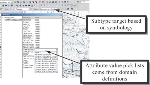 |
Figure 2. Subtype selection determines domains for some attributes. The Target control on the tool bar allows selection of the subtype for a new feature when digitizing. In this figure, assignment of a subtype value (fault) determines the value domain for the ConceptID attribute. |
Relationships
The geodatabase model includes provision for representing relationships as relationship classes. These may be either simple or complex (geodatabase parlance). Simple relationships are essentially relational table joins stored in the geodatabase. Complex relationships are represented by a correlation table in the geodatabase, allowing each relationship link to have associated properties. Both kinds of relationships appear in the geodatabase table of contents viewed in ArcCatalog (fig. 3). The ArcMap interface allows editing of data in related tables by selecting a source object in the relationship. Thus, a line or polygon may be selected, and properties specified in related tables may be edited. The Identify dialog (opened by clicking on a feature using the ‘Identify’ tool on the ‘Tools’ toolbar) allows for browsing of links to related tables, to inspect the contents of linked records. Unfortunately, there is no way to control which linked information is displayed (fig. 4). Unlike explicit joins, which may also be constructed in the ArcMap environment, fields in tables linked by a relationship class do not show up in the Table view of a feature class, and are not available for constructing queries.
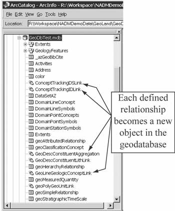 |
Figure 3. Relationship classes in ArcCatalog table of contents. |
 |
Figure 4. Identify Results dialog for geologic unit information linked to a polygon. Without significant customization, the significance of the various links is not apparent, and much unnecessary information is presented. Age of unit has a lowerBoundAge and UpperBoundAge that are both links to stratigraphic ages from a geologic time scale (such as Eocene). Each of these stratigraphic ages has a lower and upper bounding age (in Ma) that are stored in linked measuredQuantity objects. Science language terms (geologic unit type and rank) are hierarchical, and the hierarchy links appear due to the defined geodatabase relationships, not only immediate parent and child terms, but also to every other term with the same parents. |
DIGITIZING WORKFLOW AND MECHANICS
The transition from digitizing coverages using ArcEdit to digitizing features in a geodatabase required rethinking the map construction workflow. Issues included when and how to generate polygons from digitized lines, the best method of editing topologic features, and procedures for editing map data. Because maps are compiled from field sheets, the AZGS map compilation process is incremental. Polygons are constructed as line work is digitized from scanned, georeferenced field sheets. First, a group of lines is digitized from a field sheet. Then, these lines are planarized (similar to ‘clean’ in Arcedit—producing nodes at line intersections and snapping where necessary) by selecting the lines and clicking the ‘Planarize Lines’ button on the Topology tool bar. The topology validator is used to fix all dangles and undershoots. Faults that end within a polygon are legal dangles and are marked as exceptions. When the line topology problems are fixed, the lines defining polygons to be generated are selected, and the ‘construct features’ button on the Topology toolbar is clicked. The Target (Editor toolbar) must be set to the geology polygon layer, and the Task (Editor toolbar) to ‘Create New Feature’. Once all polygons defined by line work on a field sheet scan have been constructed, a new field sheet scan may be started.
During the transition to map production in ArcGIS 8.3, some data were digitized using ArcEdit to produce coverages, which were then imported into geodatabase feature classes. This process worked well using the ‘Coverage to Geodatabase’ wizard, accessible by right-clicking on the geodatabase icon in ArcCatalog. This produces both a line and a polygon feature class. In order to integrate these into a single topology, so that lines or polygons may be edited keeping polygon boundaries coincident with lines, a new topology must be defined that applies the rules in Table 4 to the new feature classes. The new line and polygon feature classes must be in the same feature dataset to create the topology. Care must be taken that the cluster tolerance defined for the topology is less than the fuzzy tolerance for the coverage; if the fuzzy tolerance is too small, the coverage lines must be generalized (at the workstation Arc command line) using a weed tolerance slightly greater than the cluster tolerance for the geodatabase topology.
The ‘topology edit’ tool (Topology toolbar) works well for editing polygon boundaries with coincident lines. When editing at the junction of three or more polygons must be done, it is commonly easier to use the standard edit tool (Edit toolbar) with snapping set to “on” between the line and polygon features. The snap environment—which feature classes will snap, and whether snapping will occur between nodes, vertices, or edges—is set using the ‘Snapping. . .’ choice on the Editor drop-down menu on the Editor tool bar. The snap tolerance is set via the ‘Editing Options’ dialog accessed through the ‘Options’ choice on the Editor drop-down menu on the Editor tool bar. A value of 3–5 meters (m) seems to work well for the Arizona spatial reference system. Setting the ‘Sticky move tolerance’ in the same dialog to a value of 5–10 pixels avoids frustration with features being selected and moved accidentally when trying to select nearby features.
Adding and removing polygons can be done in a variety of ways. The topology tools offer several features that can facilitate the process. A polygon may be created by splitting an existing polygon. Set the edit target to the polygon layer, and select the ‘Cut polygon features’ choice on the Task drop-down menu on the Editor tool bar. Select the polygon to split, and with the ‘Sketch tool’ (pencil button), draw the line where the polygon will be split. After splitting, validate the topology, and the new polygon boundary will show up as a violation of the ‘Polygon boundaries must have coincident geologic lines’ rule (Table 4). In fact there are two topology errors, one for each polygon, but both are fixed by creating a line along the boundary. Clicking on the topology error with the ‘Fix topology error tool’ (Topology toolbar) selects both errors. Right clicking with the ‘Fix topology error tool’ provides choices for fixing the error, and ‘Create feature’ is the obvious choice. Unfortunately, this will create two new, coincident lines, and a new topology error because of the rule ‘Lines may not intersect’. Some trouble can be saved by having the ‘Error Inspector’ window open (click the ‘Error Inspector’ button on the Topology toolbar); then search for errors after doing the polygon split, right-click on one of the ‘Lines may not intersect’ errors and select ‘Create feature’. This creates just one line, and finishes the split operation.
When the new polygon overlaps more than one existing polygon, the new polygon may be digitized on top of the existing polygons. Validating the topology at this point results in errors because of overlapping polygons, and a polygon boundary without coincident lines. Using the ‘Fix topology error tool,’ right click on the line error produced along the new polygon boundary and select ‘Create feature’ to create a line on the new polygon boundary. Select this line and all existing lines it intersects and click the ‘Planarize Lines’ button on the topology tool bar to split the existing lines where they intersect the new polygon boundary (and vice versa). Using the ‘Fix topology error tool’, right-click on the area error created by the new polygon (overlap with existing polygons) and select ‘Create feature’ to insert the new polygon into the map topology by intersecting it with the existing polygons. The map geometry must then be cleaned up by 1) merging the parts of the new polygon created where it overlapped different polygons in the original map; and 2) deleting lines that were polygon boundaries within the new polygon.
MAP UNIT DESCRIPTION
The basic elements of geologic unit description are shown in figure 5. The GeologicUnitLexicon is a vocabulary of geologic unit names. Each is associated with at least one description in the GeologicUnitDescription table that is called the normative description. Other descriptions in the GeologicUnitDescription table may be associated with a geologic unit. Each geologic unit description pertains to some body of rock represented by an Extent object. This may represent an outcrop (point location), the rock exposed in some area (one or more polygons), or the entire geologic unit (in the case of the normative description). The geologic unit description contains links to terms from a geologic vocabulary (NGMDBScienceLanguage) that specify various properties of the unit (links labeled ‘PropertyTermLinks (many)’ in Figure 5). Some properties may be specified by complex data objects that are collections of more specific properties and relationships. Some examples include geologic unit thickness, age, surface character, and genesis. A geologic unit is composed of one or more parts, represented by the aggregation relationship from GeoUnitDescription to GeoUnitPart in the top left of figure 5. The parts of a geologic unit may be 1) an Earth material specified by a term in a geologic lexicon of lithologic classes (NGMDBCompoundMaterialLexicon); 2) an Earth material specified by an Earth material description but not part of a vocabulary (CompoundMaterialDescription); 3) a geologic unit from a geologic unit lexicon (GeoUnitLexicon), for instance, in the description of a stratigraphic group, the parts are named (in a lexicon) formations; or 4) a geologic unit description not part of a lexicon (GeoUnitDescription).
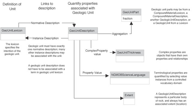 |
Figure 5. Generalized scheme for geologic unit description. |
A more detailed entity-relationship diagram for the implementation of geologic unit description is shown in figure 6. A summary of the fields in each table is included in the appendix. Each table includes several standard fields. The Name field contains a text string used to identify each data instance. In the case of lexicon terms (GeologicUnit and CompoundMaterial) the name is the preferred name associated with a concept. For description tables, the name identifies the description, as an abbreviated summary of the description or some user-defined name. Tracking links (see below for discussion of ‘ID’ and ‘DS’ suffixes) associate data instances metadata documenting processing history and intellectual sourcing of data. OriginDate is an automatic field that records the data and time a record was created in the database.
 |
| Figure 6. Entity-Relationship schema for geologic unit description. Pairs of fields with the same name with suffixes ‘ID’ and ‘DS,’ such as GeoAgeID/GeoAgeDS, are links to data that may come from different tables. The ‘. . .DS’ value identifies the table that contains the linked record, and the ‘. . .ID’ value identifies the appropriate record in that table. This mechanism allows for different representations of a property’s value; for instance a geologic age may be a stratigraphic age range as shown in this diagram, but may also be reported as an isotopic age or a single stratigraphic age from a stratigraphic time scale. Other tables are used to describe geologic unit thickness, particle geometry, surface characteristics, and to record tracking (metadata) information. These have been omitted for simplicity. |
Each geologic unit definition record in the GeologicUnitLexicon table contains a link to a type and rank term in the NGMDBScienceLanguage (GeoUnitTypeID, RankID); a name for the unit; a free text description explaining the intent of the unit; and the URL of the GeoLex record for the unit, if one exists. The geologic unit definition also includes a link to a normative description (DescID/DescDS), and a link to a geologic age description (GeolAgeID/GeolAgeDS). These links are compound (foreign key is based on two fields), with a ‘. . .DS’ value that specifies the data container (such as a table or view in a relational database) for related data, and the ‘. . .ID’ value identifies the particular linked data instance in that container. This convention holds for all table attributes that occur as pairs with the same name followed by the suffixes ‘. . .ID’ and ‘. . .DS’.
The GeoUnitPartDescription entity correlates a geologic unit description with its parts, which may come from GeoUnitLexicon, GeoUnitDescription, NGMDBCompoundMaterialLexicon, or CompoundMaterialDescription. Each part has an associated proportion, specified by a typical, minimum, and maximum value. The MeasuredQuantityTypeID attribute is a link to a science language term that specifies how the proportion values are to be interpreted—either as a value with uncertainty bounded by minimum and maximum values, or as a range with upper and lower bounds and a default typical value. Because the parts of a geologic unit may include other geologic units, the data structure is recursive. If the implementation constraints allow the most general application of this structure, standard SQL queries cannot be used to search for the occurrence of some particular lithology instance as a part of a geologic unit. The descriptions constructed thus far have avoided this difficulty by requiring geologic unit parts to come from a standard lithology lexicon.
A geologic unit also has an age, which may be specified in a number of ways, including a single term from a stratigraphic time scale (a geologic vocabulary), a range of ages specified by lower and upper bounds from a time scale, or a single numeric age (with error bounds) for an isotopically dated unit. In the implementation diagrammed in figure 6, geologic age is represented by a StratigraphicAgeRange entity that defines a lower and upper age boundary specified using named ages from a stratigraphic time scale. The StratAgeRangeConnector attribute specifies the relationship between the age range bounds and the occurrence of a specified event during that time period (see table 6). The time scale is represented by the StratigraphicTimeScale table, which associates each named time interval (such as Jurassic) with lower and upper time boundaries in million years before present (Ma) specified by linked MeasuredQuantity records. The MeasuredQuantity table is a general representation for measurements, and allows recording of uncertainty bounds, range quantities, measurement method, and tracking information.
| Table 6. Age range relationship types. | |
|
Name
|
Definition
|
|---|---|
|
equal
|
Minimum and maximum ages are the same.
|
|
and
|
Unit includes rocks of both minimum age and maximum age, but not ages in
between.
|
|
enum
|
Unit includes rocks of several discrete ages ranging from minimum age to maximum
age; these are enumerated by AgeLabel.
|
|
or
|
Rocks in unit are either of minimum age or maximum age, or both ages.
|
|
through
|
Unit includes rocks continuously ranging in age from minimum age through maximum
age.
|
|
to
|
Unit includes rocks discontinuously ranging in age from minimum age to maximum
age.
|
The link between geologic unit descriptions and the spatial data in a geodatabase is obtained using a relationship class that links the MapUnitID in the geology polygon feature class to the InstanceID in the GeologicUnitLexicon table. Other relationship classes in the geodatabase link the geologic unit to its geologic age, normative description, and rank definition. Because relationship classes do not allow joining on compound keys, the current implementation requires that all geologic unit definitions, geologic ages, and science vocabulary are each contained in individual tables. Some significant customization of the ArcGIS environment would be necessary to realize the full expressive power of the relational implementation outlined here. Because of the complexity of the knowledge representation necessary to fully capture geologic unit description and Earth material description in a computer analyzable form, other knowledge representation tools, including frame-based and description logic systems, are being investigated for data storage and analysis.
REFERENCES
NADMSC (North American Data Model Steering Committee), 2003, NADM conceptual model 1.0, A conceptual model for geologic map information: preliminary website release under the auspices of the Geological Survey of Canada, the U.S. Geological Survey, and the Association of American State Geologists. Available at http://nadm-geo.org/.
Richard, S.M. and Orr, T.R., 2001, Data structure for the Arizona Geological Survey geologic information system; basic geologic map data, in Soller, D. R., Ed., Digital Mapping Techniques 2001, Workshop Proceedings, U. S. Geological Survey Open-File Report 01-223, p. 167–188, http://pubs.usgs.gov/of/2001/of01-223/richard2.html.
Appendix
Data dictionary for tables in Figure 6.
Data types are as follows. Boolean, real number, and integer are standard data types. Short text is text string <256 characters long. Long text is a text string longer than 255 characters, equivalent to an MS Access memo field. Links to a specified table (such as NGMDBScienceLanguage) are the datatype required by the unique identifier (key) for that table. The project is in the process of converting to system-assigned globally unique identifiers (GUIDs) as the key for data objects. Links to a table specified as a ‘description object’ are compound, with the first part identifying the record in the table (foreign key), and the second part identifying the table that is the source of the linked data. Appendix Table 1 lists fields that are present in all other tables.
| Appendix Table 1. Fields that are present in all tables. | |
|
Attribute Name
|
Definition
|
|---|---|
|
ObjectGUID
|
Unique identifier for a data object in a dataset. Originally implemented as autonumber
long integer, now converting to GUID (globally unique identifiers).
|
|
Name
|
Short text that specifies words used to identify a data object or observation
instance. For many data objects, this represents a text summary of a complex
value for display in reports or pick lists.
|
|
Tracking
|
Link to tracking record.
|
|
OriginDate
|
Automatic field, database supplies time stamp for creation of data object.
|
| Appendix Table 2. CompoundMaterialDescription. | |
| Entity representing description schema for Compound EarthMaterial from NADM–C1 model. | |
|
Attribute Name
|
Definition
|
|---|---|
|
Description
|
Long text description, for use by human reader.
|
|
IsNormative
|
Boolean value, true if a description defines a term in some controlled vocabulary.
|
|
UnitDimension
|
Simple real number, > 0, that defines the minimum size of sample necessary to characterize the material
(give diameter of approximately spherical sample, in meters).
|
|
ConsolidationTerm
|
Link to term in NGMDBScienceLanguage that specifies the degree of consolidation
of a compound material.
|
|
Color
|
Short text description of the color of some object.
|
|
Process
|
Link to term in NGMDBScienceLanguage that specifies a geologic process associated
with the genesis of an EarthMaterial, GeologicUnit, or GeologicStructure,
or that may be associated with a GeneticEvent in a Genesis description.
|
|
Environment
|
Link to term in NGMDBScienceLanguage that specifies a geologic environment (location)
associated with the genesis of an EarthMaterial, GeologicUnit, or GeologicStructure,
or that may be associatedwith a GeneticEvent in a Genesis description.
|
|
ParticleGeometry
|
Link to description object that specifies the geometry of all constituent particles
in a compound material, or the geometry of some particular constituent particles
in a compoundMaterial.
|
|
FabricTerm
|
Link to term in NGMDBScienceLanguage that specifies the fabric displayed by a
compoundMaterial, or by one particular constituent in a compoundMaterial.
|
|
FabricDescription
|
Long text that provides description of fabric in a compound material or displayed
by a particular constituent of a compound material.
|
|
StandardLithology
|
Link to most specific subsuming lithology term in NGMDBCompoundMaterialLexicon;
use to simplify conflation of vocabularies or to relate lithology observation
descriptions to a controlled vocabulary or lithology.
|
|
LithologyCompositionTerm
|
Link to term in NGMDBScienceLanguage to characterize general composition character
of an EarthMaterial. More than one term may apply to a material. Includes rock
names in chemical classification systems (for example, TAS).
|
| Appendix Table 3. GeologicUnitDescription. | |
| Table summarizing major attributes of a bedrock or surficial geologic unit. Frequency on geologic unit part used to qualitatively express abundance, also allows to express constituents that are never present. Concrete table in NGMDB_P3 database only allows single values for Color, Process, Environment, and Metamorphic grade. | |
|
Attribute Name
|
Definition
|
|---|---|
|
Description
|
Long text description, for use by human reader.
|
|
IsNormative
|
Boolean value, true if a description defines a term in some controlled vocabulary.
|
|
GeologicUnit
|
Link to described geologic unit in GeologicUnit Lexicon, if the description is
associated with a named unit. If description is normative, link is to
defined unit.
|
|
Extent
|
Link to an extent description object or directly to a spatial object that specifies
the geographic region over which some description applies.
|
|
Color
|
Short text description of the color of some object.
|
|
Process
|
Link to term in NGMDBScienceLanguage that specifies a geologic process associated
with the genesis of an EarthMaterial, GeologicUnit, or GeologicStructure,
or that may be associated with a GeneticEvent in a Genesis description.
|
|
Environment
|
Link to term in NGMDBScienceLanguage that specifies a geologic environment (location)
associated with the genesis of an EarthMaterial, GeologicUnit, or GeologicStructure,
or that may be associated with a GeneticEvent in a Genesis description.
|
|
BodyGeometry
|
Link to term in NGMDBScienceLanguage that specifies the geometry of a geologic
unit considered as a distinct body of material.
|
|
MetamorphicGrade
|
Link to term in NGMDBScienceLanguage that specifies the field metamorphic grade
of a Rock or GeologicUnit.
|
|
GeologicAge
|
Link to geologic age description object that may be in StratigraphicAgeRange,
GeochronDate (not depicted here), or StratigraphicAge table.
|
|
GeologicUnitSurfaceCharacter
|
Link to geologic unit surface character description table (not depicted here,
includes attributes for surface dissection, varnish development, soil
development, etc.).
|
|
GeologicUnitThickness
|
Link to geologic unit thickness description entity (not depicted here).
|
| Appendix Table 4. GeologicUnitLexicon. | |
| Standard vocabulary of Geologic unit names that have an associated normative description. | |
|
Attribute Name
|
Definition
|
|---|---|
|
Definition
|
Long text used to specify the definition of some concept, for use by human readers.
|
|
IsFormal
|
Boolean value, true if geologic unit is formally defined.
|
|
GeolexURL
|
Short text that specifies a universal resource locator (URL) for the Geolex record
associated with a geologic unit.
|
|
GeologicUnitType
|
Link to term in NGMDBScienceLanguage that defines the type of a geolgoic unit.
Required term specifies type according to North American Stratigraphic
Code. Other type terms may classify the unit according to other criteria
(genetic process, environment.
|
|
Rank
|
Link to term in NGMDBScienceLanguage that defines the stratigraphic rank of a
geologic unit.
|
|
GeologicAge
|
Link to geologic age description object that may specify a stratigraphic age,
stratigraphic age range, isotopic date, or general age range. Schema
shows implementation of stratigraphic age range with link to StratigraphicAgeRange
table.
|
|
GeologicUnitNormativeDescription
|
Link to GeologicUnitDescription that is the normative description for the geologic
unit.
|
| Appendix Table 5. GeologicUnitPartDescription. | |
| Entity that contains properties of a part of a geologic unit. Tracking is inherited from GeologicUnitDescription. A GeologicUnitPart is always associated with a GeologicUnitDescription. | |
|
Attribute Name
|
Definition
|
|---|---|
|
Sequence
|
Integer to order a collection of data objects.
|
|
GeologicUnitPart
|
Compound link to geologic unit or earth material lexicon or description object;
identifies geologic unit part. May link to GeologicUnitLexicon, GeologicUnitDescription,
NGMDBCompoundMaterialLexicon, or CompoundMaterialDescription.
|
|
GeologicUnitPartRole
|
Link to term in NGMDBScienceLanguage, specifies role of a geologic unit part
in the entire geologic unit.
|
|
GeologicUnitDescription
|
Link to GeologicUnitDescription from a geologic unit part; links part to whole.
|
|
TypicalProportion
|
Real number between 0 and 1, typical or default value to use for the proportion
of a constituent in an aggregation.
|
|
MinimumProportion
|
Real number between 0 and 1, minimum value to use for the proportion of a constituent
in an aggregation.
|
|
MaximumProportion
|
Real number between 0 and 1, maximum value to use for the proportion of a constituent
in an aggregation.
|
|
MeasuredQuantityType
|
Link to term in NGMDBScienceLanguage specifying types of measured quantities—such
as range, value with symmetric uncertainty, value with assymetric uncertainty.
|
|
ProportionString
|
Short text summarizes the proportion attribute for a constituent, for display
in text controls.
|
|
ValueBasisString
|
String specifying how a default or typical value for a measured quantity was
selected. Need to see what gets put in here to generate a controlled
vocabulary.
|
|
MeasurementMethod
|
Link to term in NGMDBScienceLanguage that specifies the method used to determine
a measured.
|
| Appendix Table 6. GeologicUnitThicknessDescription. | |
| Description of thickness of a geologic unit--may be individual bed(s), or entire unit. Thickness quantity is multiple to allow stating things like ‘normally this thick’, never less than this thick’. . . | |
|
Attribute Name
|
Definition
|
|---|---|
|
Notes
|
Long text, for use by data compiler to enter general comments that pertain to
a data object.
|
|
Extent
|
Compound link to an extent description object or directly to a spatial object
that specifies the geographic region over which some description applies.
|
|
GeologicUnitDescription
|
Link to GeologicUnitDescription that thickness measure is associated with.
|
|
MeasuredQuantityType
|
Link to term in NGMDBScienceLanguage specifying types of measured quantities—
range, value with symmetric uncertainty, value with assymetric uncertainty.
|
|
ThicknessSummary
|
Short text, original free text description of geologic unit thickness if from
published source; summary text to display thickness value.
|
|
NumericValue
|
Numeric value for typical or default value of a measured quantity. Method of
determining typical value specified by ValueBasis.
|
|
MaximumValue
|
Numeric value for maximum value in range, or upper bound on error envelope.
|
|
MinimumValue
|
Numeric value for minimum value range, or lower bound on error envelope.
|
|
ValueBasisString
|
String specifying how a default or typical value for a measured quantity was
selected. Need to see what gets put in here to generate a controlled vocabulary.
|
|
MeasurementMethod
|
Link to term in NGMDBScienceLanguage that specifies the method used to determine
a measured.
|
|
MeasurementUnitTerm
|
Link to term in NGMDBScienceLanguage that identifies the units of measure for
an associated measured quantity.
|
| Appendix Table 7. MeasuredQuantity. | |
|
Entity for representing measured quantities that have associated units, measurement
method, quantity, type. May be value with uncertainty; upper and lower
bounds define uncertainty envelop, may be assymetric. May be range,
with typical (default) value.
|
|
|---|---|
|
Attribute Name
|
Definition
|
|
Notes
|
Long text, for use by data compiler to enter general comments that pertain to
a data object.
|
|
MeasuredQuantityType
|
Link to term in NGMDBScienceLanguage specifying types of measured quantitiesčrange,
value with symmetric uncertainty, value with assymetric uncertainty.
|
|
NumericValue
|
Numeric value for typical or default value of a measured quantity. Method of
determining typical value specified by ValueBasis.
|
|
ValueBasisString
|
String specifying how a default or typical value for a measured quantity was
selected. Need to see what gets put in here to generate a controlled
vocabulary.
|
|
MaximumValue
|
Numeric value for maximum value in range, or upper bound on error envelope.
|
|
MinimumValue
|
Numeric value for minimum value range, or lower bound on error envelope.
|
|
MeasurementUnitTerm
|
Link to term in NGMDBScienceLanguage that identifies the units of measure for
an associated measured quantity.
|
|
MeasurementMethod
|
Link to term in NGMDBScienceLanguage that specifies the method used to determine
a measured.
|
| Appendix Table 8. NGMDBCompoundMaterialLexicon. | |
| Controlled vocabulary of compound material definitions. | |
|
Attribute Name
|
Definition
|
|---|---|
|
Definition |
Long text used to specify the definition of some concept, for use by human readers. |
| ParentTerm | Link to subsuming concept in this vocabulary. |
| isAbstract | Boolean, true if a term is ‘abstract’ (such as the name of a vocabulary) and can not be used to populate an attribute. |
| Appendix Table 9. NGMDBMineralLexicon. | |
| Controlled vocabulary of mineral definitions. | |
|
Attribute Name
|
Definition
|
|---|---|
|
ChemicalFormula
|
Short text, chemical formula defining a chemical composition.
|
|
ParentTerm
|
Link to subsuming concept in this vocabulary.
|
|
Level
|
Link to term in controlled vocabulary specifying the rank of a mineral name,
from Micronex beta distribution (http://www.micronex.ca/ from http://www.georeferenceonline.com/).
|
| Appendix Table 10. NGMDBScienceLanguage. | |
| Terminology for description of geologic features | |
|
Attribute Name
|
Definition
|
|---|---|
|
Definition
|
Long text used to specify the definition of some concept, for use by human readers.
|
|
isAbstract
|
Boolean, true if a term is ‘abstract’ (such as the name of a vocabulary) and cannot be used to populate an attribute.
|
|
ParentTerm
|
Link to subsuming concept in this vocabulary.
|
|
Vocabulary
|
Link to term in NGMDBScienceLanguage defining the vocabulary that contains this
term.
|
|
TrackingNote
|
Short text notes on origin of a science language term, for simplified tracking;
includes reference to publication and person, date of entry.
|
| Appendix Table 11. StratigraphicAgeRange. | |
| Entity to represent a stratigraphic age that has a lower and upper bound expressed by a link to a named time interval in a Stratigraphic time scale. | |
|
Attribute Name
|
Definition
|
|---|---|
|
Notes
|
Long text, for use by data compiler to enter general comments that pertain to
a data object.
|
|
StratAgeRangeOlderBound
|
Link to StratigraphicTimeScale for named time interval that is older bounding
interval for a stratigraphic age range.
|
|
StratAgeRangeYoungerBound
|
Link to StratigraphicTimeScale for named time interval that is younger bounding
interval for a stratigraphic age range.
|
|
StratAgeRangeConnector
|
Link to term in NGMDBScienceLanguage that specifies the distribution of rock
unit age in time during a stratigraphic age range interval, for example, ‘to’, ‘and’, ‘or’, ‘through’. ‘enum’ indicates that more than two ages are assigned.
|
|
StratTimeScaleSource
|
Link to NGMDBScienceLanguage definition that defines a stratigraphic time scale.
|
| Appendix Table 12. StratigraphicTimeScale. | |
| Ordered, hierarchical partition of geologic time, with named time intervals. Parent-child links are partonomy. Sequence is for sorting intervals of similar rank, and sorting time scale. | |
|
Attribute Name
|
Definition
|
|---|---|
|
ParentTerm
|
Link to subsuming concept in this vocabulary.
|
|
Sequence
|
Integer to order time intervals.
|
|
AgeYoungerBound
|
Link to MeasuredQuantity table that specifies the younger bound in estimated
absolute years, for a stratigraphic time interval.
|
|
AgeOlderBound
|
Link to MeasuredQuantity table that specifies the older bound in estimated absolute
years, for a stratigraphic time interval.
|
|
StratigraphicAgeRank
|
Link to term from NGMDBScienceLanguage that classifies rank of a named time interval
unit such as eon, period, stage. . .
|