
Digital Mapping Techniques '04— Workshop Proceedings
U.S. Geological Survey Open-File
Report 2004–1451
Implementing NADM C1 for the National Geologic Map Database
1Arizona Geological Survey, 416 W. Congress # 100, Tucson, AZ 85701; Telephone: (520) 770-3500; Fax: (520) 770-3305; e-mail: Steve.Richard@azgs.az.govBACKGROUND
This report is a summary of progress on implementing the NADM C1 conceptual model (NADMSC, 2004) as a production-scale prototype for a U.S. Geological Survey –Association of American State Geologists (AASG) National Geologic Map Database (NGMDB, Soller and Berg, 2003). The implementation uses standard relational database technology, and is designed to function as an ESRI geodatabase or as a standalone, non-geographic database. The implementation is designed for depth of knowledge representation and flexibility, not for simplicity or performance. The NGMDB will be a data archive for geoscience information, with provision to record alternative interpretations, evolving terminology and science paradigm, uncertainty, incomplete knowledge, and metadata pertaining to data acquisition, processing, and automation. The objective is integration of geologic data from published maps by different authors at different scales, as well as newly acquired field data.
In more concrete terms, the objective of the project is to design and implement a scalable database for storing geologic descriptions, particularly those related to geologic maps (e.g., geologic units, lithology, and geologic structures), as well as the location and geometry of mappable features. Development has been ongoing for several years. The development of an underlying conceptual model and science vocabulary has taken place in a community arena (the North American Data Model Steering Committee, http://nadm-geo.org/) in order to achieve some level of standardization. Physical implementation has been guided by discussions with mappers in the U.S. National Cooperative Geologic Mapping Program. Implementation of an enterprise-scalable database requires that we address business rules for security, ownership, and authority of data contained in the database. Integration of geologic data from different authors will require the maintenance of documentation (metadata) for each data object, such that the original source of information can be determined. Because it is critical for users to get data into and out of the database, considerable effort is being spent to develop a software interface to the NGMDB prototype database
NADM MODEL
Our underlying framework for information system development is the NADM C1 conceptual model(NADMSC, 2004). This model specifies the basic kinds of geologic things of interest and how they are described. It does not specify a database implementation. Table 1 summarizes significant concepts from the NADM C1 model that are used in the NGMDB implementation.
| Table 1. Major concepts in NADM C1, as used in the NGMDB implementation. | |
|
|
|
|
Concept
|
Scope and rationale
|
|---|---|
|
|
|
| EarthMaterial |
A naturally occurring substance in the Earth. EarthMaterial represents substance, and is thus independent of quantity or location. Ideally, EarthMaterials are defined strictly based on physical and chemical properties, but because of traditional geologic usage, genetic interpretations enter into the description as well. Does not include melted rock (magma or lava). Many concepts related to water or petroleum have not been modeled in this version. |
| GeologicEvent |
An identifiable event during which one or more geologic processes act to modify geologic entities. A GeologicEvent may have a specified GeologicAge and GeologicEnvironment. An example might be a cratonic uplift event during which erosion, sedimentation, and volcanism occur. |
| GeologicProcess |
A function, possibly complex, that acts on one geologic entity to produce another geologic entity at a later time. Process is time independent; some GeologicProcesses are observable in the present at work in the world or in the laboratory, others can only be inferred from observing the results of the process. Processes take one or more of EarthMaterial, GeologicUnit, or GeologicStructure as input and have one or more of EarthMaterial, GeologicUnit, or GeologicStructure as output. |
| GeologicProperty |
An inherent feature used to characterize a GeologicConcept. |
| GeologicRelation |
Any of a wide variety of relationships that can exist between two or more GeologicConcepts. For example, the GeologicRelation “intrudes” is a relationship between an intrusive igneous rock and some host rock. Includes spatial, temporal, sequence, correlation, and parent/child relations. Many of the relationships in NADM-C1.0 (particularly attribute links and parent-child links) are not explicitly modeled as kinds of GeologicRelation. |
| GeologicStructure |
A configuration of matter in the Earth based on describable inhomogeneity, pattern, or fracture. The identity of a geologic structure is independent of the material that is the substrate for the structure. There are almost always strong dependencies between the nature of the material substrate and the kinds of structure that may be present. Geologic structures are more likely to be found in, and are more persistent in, consolidated materials than in unconsolidated materials. Properties like ‘clast-supported’, ‘matrix-supported’, and ‘graded bed’ that do not involve orientation are considered kinds of GeologicStructure because they depend on the configuration of parts of a rock body. Includes sedimentary structures. |
| GeologicVocabulary |
A collection of concept definitions, each associated with a preferred name, and usually organized in some logical fashion such as in a hierarchy. The preferred name associated with a concept in a GeologicVocabulary is a proxy for the collection of property values and relationships specified in the definition. The vocabulary makes the definitions of these concept instances available to apply in other descriptions without having to reconstruct the entire description denoted by the concept definition. Examples of geologic vocabulary include a collection of standard rock types, a stratigraphic lexicon, or a geologic time scale. |
| Legend |
An ordered collection of LegendItems. A map legend specifies a collection of symbols (including patterns and colors) displayed on a geologic map or cross-section, along with the meaning or geologic description assigned to each symbol. |
| LegendItem |
An association of a concept or description with a symbol. Each LegendItem instance represents a single entry in a map legend that describes either a single entity or a single class of entities occurring on a geologic map or cross-section. |
| MapDescription |
All of the descriptive information that accompanies the graphic portion of a geologic map or cross section. Includes descriptive text, symbols and their explanations, associated graphics, etc. |
| SpatialObject |
A description of the geometry (size, shape, and location) of an occurrence. Commonly represented as points, lines, or polygons. |
| GeologicUnit | A geologic unit is a part of the solid Earth that is identified by its geologic characteristics, has definable, locatable boundaries, and is persistent in time. Excludes non-material, temporal units. It is a body of earth material distinguished from adjoining material on the basis of content (lithologic or fossil), inherent attributes, physical limits, geologic age, or some other property or properties [adapted from NACSN, 1983, p.22; http://www.agiweb.org/nacsn/code2.html]. Corresponds to ‘stratigraphic unit’ in the North American Stratigraphic Code. Commonly used properties include composition, texture, included fossils, magnetic signature, radioactivity, seismic velocity, and age. Sufficient care is required in defining the boundaries of a unit to enable others to distinguish the material body from those adjoining it [NACSN, 1983]. |
|
|
|
IMPLEMENTATION
Issues-Extensions in NGMDB Model
Because the NADM C1 model is conceptual, it does not specify the details that must be implemented in a database. The following discussion lists some of the property extensions and implementation decisions that were made in developing the NGMDB prototype.
Numerical measured quantities may be represented by specifying a typical value, for example when an analysis requires a single ‘best’ value for the quantity. Alternatively, minimum and maximum values may be used to specify bounds on an uncertainty envelope (either symmetric or asymmetric about the typical value), or the upper and lower bounds on a value range. Measurement units are specified from a standard set of terms. A quantity type term in the database indicates whether the value is an average with standard deviation bounds, a range value, a value with asymmetric uncertainty bounds, or a single value with no uncertainty estimate.
The NADM C1 model does not provide for schema representing basic field observation locations for newly acquired field data. The NGMDB model has an abstract ObservationLocation feature type that is the supertype for field data acquisition sites—Station for point data, and Section for observations along a track (line) and AreaOfInterest for observations pertaining to an area. These model elements are based on the XMML site and specimen model by Simon Cox (2004, https://www.seegrid.csiro.au/twiki/bin/view/Xmml/SitesAndSpecimens/). An observation location may have one or more associated structure observations (measured orientations of structures), text descriptions, images (sketch, photo), or samples.
Boreholes are not accounted for by the NADM C1 model. NGMDB implements a simple model for borehole data based on XMML, in which a borehole is modeled as a subtype of Section, a kind of observation location. The borehole collar point feature represents the XYZ location of the intersection of a borehole with the Earth surface. A borehole may be reentered with new boreholes drilled as splays from an existing borehole. Thus, one or more boreholes may be associated with a single borehole collar. Each borehole may be associated with an ordered collection of borehole segments that constitute an XMML interval log. Each borehole segment may have associated structure observations, text descriptions, images, or samples.
The Morphology property of GeologicUnit (see Plate 3, NADMSC, 2004) is implemented through links to a standard list of geologic unit morphology terms, and in the case of lithostratigraphic units, to a numerical value for thickness. The GeometricDescription property of GeologicUnit in NADM C1 has been expanded for lithostratigraphic (bedded) units to describe bedding style and bedding pattern with standard terms, and bedding thickness with either a standard term or a numerical thickness value. After discussion with geologists who are mapping surficial deposits (mostly in the arid southwest of North America), the descriptive properties associated with surficial geologic units were expanded to include terms for degree of dissection, surface armoring (pavement development), soil development, clast weathering character and style, and varnish development. Additional properties are probably necessary to fully describe surficial deposits in glacial, polar, temperate, and tropical environments.
The NADM particle geometry description (see Plate 2, NADMSC, 2004) has been implemented with additional properties grouped as particle shape and particle size descriptions. Particle shape properties include roundness, form, and degree of crystal face development. Particle size description may include quantitative specification of particle diameter (mean, median, maximum, etc.), as well as terms specifying sorting, particle size (diameter), and particle size range.
The NGMDB implementation allows multiple values to be assigned for many properties, through an attribute relationship correlation table. This mechanism allows qualifiers and metadata to be associated with each attribute value assignment. Qualifiers provide information on frequency that a value is observed, confidence in value assignment, and intensity of development of an attribute. Ability to assign a frequency to some value allows the expression of negation, i.e., the fact that a particular value is not allowed. The ability to express confidence allows representation of specific, estimated or guessed property values at low confidence, and less specific generalized property values at higher confidence. Metadata associated with attribute value assignment can record the measurement procedure, or more detail on evidence for assigning a value (e.g., why the environment attribute is assigned as ‘fluvial’).
In a distributed information system, data from many sources may be integrated for a single analysis, and evaluation or interpretation of results will require knowledge of the provenance of individual units of data. The feature level metadata (tracking) implemented in this database allows for the recording of links to citations for published sources, the person, organization, and project responsible for original data acquisition, and the processing steps involved in automating the information.
NGMDB Implementation Framework
Based on previous experience with geologic map database design and implementation, especially the evolution of implementations based on the Johnson et al. (1998) model version 4.3 (see http://nadm-geo.org/ for examples listed under “Data Model Design Team”), it became apparent that a widely applicable geoscience database implementation must be adaptable to evolving data requirements. In order to provide the flexibility and expressiveness required for a widely applicable geoscience information system, we are implementing a relatively abstract logical model that allows different users to configure the data structure to include entities and properties appropriate for their requirements. The underlying goal is to code the semantics of the data into the database to the maximum extent possible, as opposed to structurally incorporating semantics into data design. This requires including vocabularies that define terminology in the data, and encoding the data schema in the data. The most extreme version of such a design results in a one-table database (see design of the Protégé knowledge tool database backend, http://protege.stanford.edu/doc/design/jdbc_backend.html). This results in maximum flexibility and minimum comprehensibility of the raw data store. The NGMDB design documented in this paper includes a relatively small number of physical ‘base tables’ for standard kinds of geologic descriptions, and a standardized mechanism for extending these with properties of interest for a particular application.
The implementation builds on Arizona Geological Survey (AZGS) designs documented in Richard (2003) and Richard and Orr (2001), the Canadian Cordlink 5.2 design (Brodaric et al., 1999), and previous NGMDB prototype designs (Soller et al., 2002; Brodaric and Hastings, 2001, 2002). The design has been influenced by the Ontology Web Language (OWL), analysis of the data structure used by the LegendBurster tool (http://www.georeferenceonline.com/LegendBurster/), and various models proposed as part of the International Organization for Standardization Geographic Information/Geomatics project (ISO TC211, http://www.isotc211.org/), especially the Geography Markup Language (GML, Cox et al., 2004) and Exploration and Mining Markup Language (XMML, https://www.seegrid.csiro.au/twiki/bin/view/Xmml/WebHome/).
The NGMDB implementation of the NADM C1 conceptual model revolves around three logical elements—Vocabularies, Description Schema, and Data Instance (Figure 1). Vocabularies are collections of terms and text definitions, analogous to GML Dictionary and Definitions (Cox et al., 2004). A Vocabulary constitutes an enumeration of things thought to exist in a domain or of possible values for properties. A Vocabulary also may include relationships between the represented concepts (terms), in particular a ‘kind of’ or subsumption hierarchy where appropriate. A mature vocabulary also might include thesaurus type relationships, to allow users to map terms between different vocabularies, and search for similar or related terms within a vocabulary. The Description Schema is an explicit representation of the implemented data model that is part of a dataset; analogous to an XML schema contained in a .xsd document. The Description Schema represents the data model, including kinds of objects, their properties, relationships between objects, and rules that determine valid database conditions. Data Instances are valid descriptions based on the Description Schema, each of which specifies attribute values for some entity of interest.
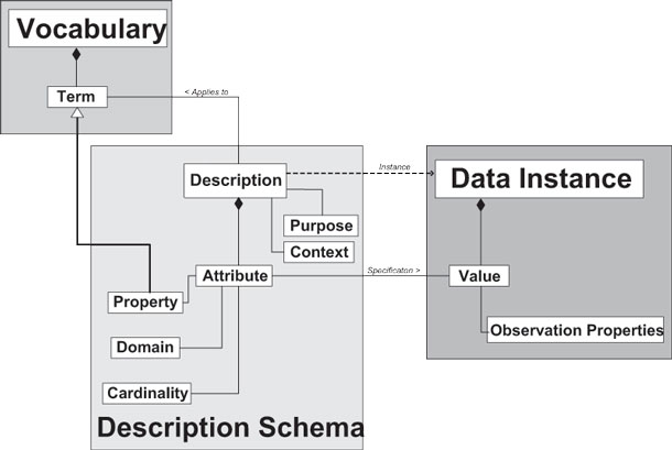 |
Figure 1. Logical framework for NGMDB implementation. |
Vocabulary Tables
Vocabulary tables contain collections of terms with associated text scope notes or definitions. If appropriate, the terms may be structured with parent-child links in the vocabulary table to define a tree hierarchy. The vocabulary defines a collection of shared concepts that may be used to classify observations, or to specify attribute values. The terms in the vocabularies are used to populate pick lists in the user interface that is under development. Each vocabulary table includes a unique identifier for each concept, the preferred name (the term) by which the concept is communicated between human users, a text notes to convey to users the meaning of the concept, and a link to a tracking record that supplies information on the source of the term and its definition.
Table 2 is a summary of the vocabulary tables implemented for the NGMDB prototype. Because the structure of each of these tables is the same, they could all be implemented in a single physical table. They have been implemented in separate tables to make them more portable – different vocabularies will be useful in different environments depending on the audience and the purpose for the geologic data. The geologic unit vocabulary will include names for geologic units that are found in the area of interest, and the terms required in the standard lithology and mineral vocabularies are determined by the kinds of Earth materials that are found. Different geologic time scales will require different vocabularies of stratigraphic eras. Richard et al. (2003) discuss some issues with integrating data using different vocabularies. The basic rule is that data integration is simplest if everyone is using the same vocabulary. Conflation of data using different vocabularies will require a thesaurus that matches terms in one vocabulary with those in the other, and may involve information loss.
| Table 2. Vocabularies in the NGMDB prototype implementation. | |
|
|
|
|
Vocabulary
|
Table Content
|
|---|---|
|
|
|
| GeologicUnit |
Known geologic units within some area of interest. |
| StandardLithology |
Terms associated with descriptions for standard kinds of rocks and unconsolidated material. |
| StandardMineral |
Kinds of minerals that may be constituents in compound Earth materials. |
| EntityPropertyTypes |
Kinds of properties that may be used in descriptions. |
| ScienceLanguage |
Collection of vocabularies for kinds of things and property values. In any data repository this table will include both ‘infrastructure’ terms shared by all databases, and local terms defined for use in this repository. The infrastructure includes basic geoscience terminology, plus interdisciplinary terminology (units of measurement…), and some metadata terminology used in the information system. |
| StratigraphicEra | Named eras in a geologic time scale. |
|
|
|
The science language vocabulary is really a collection of many vocabularies that enumerate kinds of phenomena, or terminological values that may be used to quantify properties. It includes vocabularies for kinds of geologic structures, geologic process, geologic units, physical properties and geologic relationships. Examples of included property value vocabularies include Earth Material genesis terms, particle size terms, particle sorting terms, particle form terms, geologic unit rank terms, consolidation degree terms, and metamorphic grade terms.
Data Schema
The NGMDB implementation includes tables that explicitly store the data schema (Figures 1, 2, and 3). This approach is similar to that used for XML documents, which have an associated schema document (xsd file) that specifies the structure of data instances, and is similar to the schema information recorded by the internal tables (‘GDB_’ tables) in ESRI geodatabases. The schema identifies a collection of entities (ESRI ‘object classes’), a collection of properties (the property vocabulary mentioned above), associates each entity with a set of properties, and specifies a value domain and cardinality for the property in that entity. In a standard relational database implementation, each entity would be a physical table, each property associated with the entity would be a field in the table, and for properties that are specified using terms the list of terms used to populate the field might be a separate table. In the NGMDB implementation, each entity is implemented by a physical table in which each row corresponds to an instance of the entity. Attribute values are associated with entity instances through AttributeRelationship instances. Each AttributeRelationship instance (row in the AttributeRelationship table) correlates an entity instance with an attribute and a value for that attribute (Figure 2), along with observation-related metadata. Attribute values are specified by value specification instances that may be a science language term, measured quantity instance, text description, or instance of another entity. The ValueEntity attribute in the AttributeRelationship table specifies the kind of value specification used.
 |
Figure 2. Diagram showing connection of logical attributes to a description through the AttributeRelationship correlation table. The AttributeRelationship table has attributes that specify the kind of attribute, and the entity type that contains the value specification. Observation-related metadata fields in AttributeRelationship are not shown. |
The Data Schema tables identify the base table associated with each entity, enumerate the properties associated with each entity, indicate how each property is specified, and specify the domain associated with each property in each entity (Figure 2, Table 3). Data Schema tables all have names with the prefix ‘Entity’.
| Table 3. Data schema tables. These tables are further explained in the Appendix. | |
|
|
|
|
Table
|
Description
|
|---|---|
|
|
|
| Entity |
Vocabulary of types of data instances (entities) that may be implemented in the database. Each type specifies a collection of properties, each with a cardinality and value domain. The instances of the entity may reside in a single physical table, or be implemented as a logical structure with a base table and attribute values associated through correlation tables. |
| EntityProperty |
Table that correlates properties defined in EntityPropertyVocabulary with entities that may specify values for the property, assign a cardinality for property values in the entity, and a domain of possible values for the property in the entity. |
| EntityPropertyDomain |
Table that defines domains that may be used to specify property values. |
| EntityPropertyDomainNodeList |
Table that explicitly enumerates terms in a value domain. May aggregate terms from one or more vocabulary entities into a single ‘domain’ or term pick list used to populate some property in some entity. If JustSelectedNode is false, then all children of a selected term should be included in the pick list. Exclude selected node is used to exclude an abstract term that is used in the vocabulary table as the root for some pick list. |
| EntityPropertyTypeVocabulary | Vocabulary of properties that may be used in descriptions. Analogous to vocabulary of classes included as subtype of GeologicProperty in NADM C1. |
|
|
|
 |
Figure
3. Data schema tables.
Lines in the diagram represent foreign key relationships between tables.
The field names at the end of lines adjacent to the table boxes indicate
the field that is the key in the table at that end of the relationship.
The EntityPropertyDomainNodeList table is used to enumerate data instances
available in the pick list for a particular attribute. The SelectedVocabularyNodeSysGUID
links are to any table that contains data objects that may be made available
in pick lists; most commonly these will be vocabulary tables—ScienceLanguage,
StandardLithology, StandardMineral. Science language link is shown here
for example. The VocabularyNodeEntityGUID identifies the table that contains
the referenced node. |
Data Instances
Data instances are implemented by a row in a base table, possibly with additional attributes associated through relationship table correlations. In the simplest case, the base table implements a single entity specified in the Data Schema. In more complex cases, multiple, related entities may be implemented in a single base table (similar to ‘object subtypes’ in ESRI geodatabase); entities that are implemented through a shared base table are referred to as logical entities. Base tables that implement logical entities include an attribute that specifies the entity type for each data instance (row) in the table. The structure of a data instance is specified by the associated entity type defined in the Data Schema.
Each Data Instance is a collection of attributes assigned to some object of interest represented in the database. The Data Instance has an associated Entity specification in the data schema tables that dictates what attributes are associated with instances of the entity, and how values for these attributes are specified. Standard, physical tables in a relational database structurally associate a data instance (row) with a collection of single-valued (0..1, depending on cardinality defined in Data Schema) attributes, each specified in a field in the table. Values may be assigned directly by numbers or strings in the field, or the field may contain a foreign key to a more complex value specification. Because the data schema is implemented directly in the table structure, entities implemented as physical tables do not require an explicit link to their entity type.
The base table for a group of logical entities (e.g. GeologicUnitDescription) contains single-valued attributes that are required by all of the logical entities implemented through that base table. The distinct logical entities implemented by a single table may have different AttributeRelationship associations, attribute domains, or cardinality constraints. Attribute values assigned through AttributeRelationship instances may have 0 to many values. Even a single-valued property may be specified using multiple AttributeRelationship instances with different observation properties. For instance a particular geologic unit may be assigned a Proterozoic age with high confidence based on stratigraphic relationship, and a middle Proterozoic age (more specific within the value range) with low confidence based on lithologic correlation. Each logical entity instance must have as one of its attributes a link to the entity definition that specifies its structure.
Base data tables are discussed in groups based on their content and use. The groups include value specification tables, GIS feature classes, section location tables, sample table, description tables, and relationship tables. The value specification tables represent observations of some individual property value specified by a numeric measurement, text, an image, or geometry. GIS feature classes represent located geographic data. Section location tables have to do with locations along observation tracks—boreholes, traverses, flightlines. The sample table catalogs physical specimens. Description tables are the base tables for standardized description of geologic objects, including EarthMaterialDescription, Geologic-UnitDescription, GeologicAge, and GeologicStructure-Description. Relationship tables are correlation tables used to establish semantic relationships between other data instances, and include several specialized tables with different relationship properties.
Value specification tables
Value specification tables record individual property values specified by a numeric measurement, text, an image, or geometry. Table 4 lists the various value specification tables. These tables are the leaf nodes in description tree structures that specify the basic units of observation and description—numbers, text, pictures, locations. Vocabulary terms that specify property values may also be viewed as leaf nodes in description tree structures, but they are shared by many descriptions. Instances in the value specification tables are unique to some particular description or location context, and if that context object is removed from the database, the value specification become useless and should be removed as well.
| Table 4. Value specification tables. These tables are further explained in the Appendix. | |
|
|
|
|
Table
|
Description
|
|---|---|
|
|
|
| Extent |
Table for specifying extents with a bounding box defined by latitude and longitude coordinates (in decimal degrees) and optional link to a spatial object. Provides mechanism for simple spatial searches in a non-GIS analysis environment. |
| DocumentLink |
Table that contains file path information for locating auxiliary documents (especially images) associated with observations. |
| MeasuredQuantity |
Table container for numerical specification of measured values with associated uncertainty, units, and measurement method. Type field distinguishes different semantics for DefaultValue, LowerBound, and UpperBound. |
| StructureObservation |
Table for recording orientation measurements of geologic structures. It combines two measured quantity instances into one description record, with additional observation properties and a default symbol specification. Strike and dip orientation data are fundamental to geologic map information, and are represented in this physical table to simplify usage. The two measured quantities represent strike and dip or plunge and trend, depending on whether the orientation represents a planar or linear structure. Observation properties record classification confidence for identification of the measured structure and measurement procedure. A default symbol identifier is included to simplify quick display of the data. |
| TextDescription | Table for value specification using bodies of text. |
|
|
|
GIS feature classes
Table 5 summarizes ESRI geodatabase feature classes used to specify location in the NGMDB implementation. All spatial data tables include fields to specify a default text label and symbol to use in map displays if no other symbolization is specified. This is to simplify the rapid display of spatial data. GeologicSurfaceTrace and GeologicUnitOutcrop are line and polygon feature classes whose locations represent observable geologic phenomena in or on the Earth. ProjectExtent is a simple polygon feature class used to define the area of interest for a project. By defining an area of interest, a spatial search can be done to locate existing data that may be of use for a project—for instance, which geologic units have been mapped in the area. AreaOfInterest, SectionLine, and Station are polygon, line, and point feature classes used to define extents associated with observations in the sense of GML Observation and Measurement (Cox et al., 2004). They represent features that are located based on where observations are made, and do not (inherently) represent the location of observable phenomena.
| Table 5. Location specification tables (ESRI geodatabase feature classes). These tables are further explained in the Appendix. | |
|
|
|
|
Table
|
Description
|
|---|---|
|
|
|
| GeologicSurfaceTrace |
Line features that represent the intersection of geologic surfaces with the map horizon. |
| GeologicUnitOutcrop |
Polygons representing the intersection of a geologic unit with the map horizon. |
| ProjectExtent |
Polygons that specify the area of interest for a project. |
| AreaOfInterest |
Polygons that are associated with one or more observations. |
| SectionLine |
Line that is the projection of a 3-D section line (e.g., borehole, flight line) into a map horizon to provide a 2-D map representation of the section. For a section line that is in the map horizon, as is typical of a measured section or traverse line, the SectionLine is the mapped trace of the section. |
| Station | Point location at which one or more observations are made, or samples are collected. |
|
|
|
Section location tables
In a variety of situations, observations are located relative to a section line—for example, locations in a borehole are typically specified in length from the top of the hole. These types of locations are treated specially in the NGMDB implementation (Table 6). Although borehole, traverse, and flightline (all kinds of sections) might be considered feature classes, the actual geometry of a borehole can not reliably be represented by the 2-D geometry available in the ESRI geodatabase structure. Each type of section is related to a SectionLine feature (Table 5) that represents the projection of the 3-D section onto a map horizon (typically the Earth’s surface). Coordinates of locations along a section line are not simply related, in general, to length along the projected line. Thus, each kind of section includes a property that specifies the origin and metric for the coordinate reference system used to specify intervals and intercepts in that section. For instance, in a borehole the coordinate system typically is measured in linear length units downward from the ground surface or kelly bushing. In a measured stratigraphic section, the metric is thickness of strata traversed from the base of the section. A section interval is a location specification based on a start and end coordinate along a section line using the reference system defined for that section line. Section intercepts are points located by a single coordinate along a section. To convert SectionInterval and SectionIntercept locations to a true three-dimensional location, the 3-D geometry of the section must be known. For example, knowing that a sample is from 10,205 feet down in a bore hole does not fully locate the sample unless the geometry of the bore hole is known—if the hole is gently inclined, the surface projection of the sample location may fall at a significant distance from the borehole collar location.
|
Table 6. Section location tables. These tables are further
explained in the Appendix.
|
|
|
|
|
|
Table
|
Description
|
|---|---|
|
|
|
|
SectionInterval
|
Spatial extent located relative to section origin along
the section line by a top and bottom coordinate. Ideally represents the
intersection of some volume with a section.
|
|
SectionIntercept
|
Spatial extent, represented by a single coordinate that
is located relative to section origin along the section line. Ideally
represents the intersection (intercept) of a geologic surface with a
section.
|
|
Borehole
|
Entity represents a borehole that is the result of a
single drilling event. Not represented as a geodatabase feature class
because the geometry is not directly represented in the currently-available,
two-dimensional GIS.
|
|
FlightLine
|
Entity represents the course of an airborne (or waterborne)
sensor.
|
|
Traverse
|
Entity represents the path followed by an observer on
the Earth’s surface.
|
|
|
|
Sample table
The sample table contains data instances that represent particular, identifiable masses of material. In this sense, they are similar to geologic units (as defined by NADM C1). The difference is that a geologic unit represents a mappable body of material—its location in the Earth is part of its identity, whereas a sample is from some location, but its identity is based on the collector’s act of identifying that material by writing a number on it or putting it in a container. Many sorts of analytical data (e.g. chemical analyses, isotopic age dates) are associated with particular samples.
Description tables
Description tables (Table 7) contain data instances that are the base instances for complex descriptions of geologic units, Earth materials, structures and geologic age interpretations. Each description table listed in Table 7 includes a collection of attributes common to all of the description tables, along with attributes that are common to all descriptions of the particular type represented by that table.
| Table 7. Description Tables. These tables are further explained in the Appendix. | |
|
|
|
|
Table
|
Description
|
|---|---|
|
|
|
|
GenericDescription
|
Physical base table that implements abstract description
class as a physical table. This is a convenience for the ESRI CASE tool,
so subtype integers are defined over generic descriptions only, and subtypes
of other description types with other physical base tables (EarthMaterialDescription,
GeologicAge(?), GeologicStructureDescription, and GeologicUnitDescription)
may have their own ESRI subtype domains. Instances in this table identify
descriptions of various types, identified in Geodatabase by ESRISubType,
and whose attributes are defined by EntityProperty correlations for the
entity (specified by DescriptionEntityGUID) associated with the description.
|
|
GeologicAge
|
Base table for geologic age description. Different specification
details may be used through AttributeRelationship links based on the
type property. Derived classes (identified by ESRISubtype / DescriptionEntityGUID)
represent age specification in different ways: time instant (a number
Ma before present, which may be inferred from 1 to many isotopic date
measurements...), a named era (geologic time scale--e.g., Miocene), or
a range specified by lower and upper bounds that may be instants, named
eras, or geologic events. These different specifications are unified
in this table with a best guess numerical minimum and maximum time coordinate
(for analysis), and a DisplayName that summarizes the interpretation
(for a data browser).
|
|
EarthMaterialDescription
|
Base table for compound Earth Material description. Identifies
description instances with a GUID and a display name, and provides values
for specifying properties common to all compound Earth Materials. Other
description attributes are linked through AttributeRelationship instances.
Includes all fields from GenericDescription (above).
|
|
GeologicStructureDescription
|
Base table for description of geologic structures. The
attributes and subtypes for these descriptions are not yet fully populated.
This table includes only properties common to all geologic structures.
Includes all fields from GenericDescription (above).
|
|
GeologicUnitDescription
|
Geologic unit description object that specifies properties
common to all geologic units; ESRI subtypes are used to apply rules for
specific kinds of geologic units that have different combinations of
properties and property value domains. Includes all fields from GenericDescription
(above).
|
|
|
|
Attributes common to all description tables specify the purpose and context (spatial and non-spatial) of the description, the described concept, and the structure of the description (see GenericDescription in Appendix Table 33). The description purpose attribute (DescriptionPurposeTermGUID) makes the intended function of a description explicit, e.g., default description, necessary property description, identifying property description, or instance description. The context specifies the domain within which the description is valid for the stated purpose. This domain may be spatial—some particular region of the Earth, or it may be human—e.g., a particular project or person, some organization, or some published authority (e.g. the Glossary of Geology. . .). These properties are included to solve the problem of distinguishing normative and instance descriptions, by recognizing that the distinction is always context and purpose dependent.
The link from a description to a ‘described concept’ (ConceptTermGUID) identifies the most specific term from an associated vocabulary that is consistent with the attributes specified in the description. For instance, an Earth material description of an indurated material of igneous origin, composed of 30% each of quartz, K-feldspar, and plagioclase would be associated the term ‘Granite’ from the standard lithology vocabulary. For identifying, default, or necessary property descriptions, this term will name the concept defined by the description. In this case, the vocabulary term may serve as a proxy for the attributes specified by the description. Any particular instance description need only specify attributes that are explicitly observed; other attributes may be inherited from the default description (if there is one) for the described concept. The structure of the description is defined by association with an entity definition in the Data Schema tables as described above. This entity definition may be used to validate the description before committing to the database, and for configuring the user interface during data entry or querying.
The GenericDescription table includes only the basic description property fields described above. This table serves as a base physical table for descriptions that do not have required attributes, or are deemed to not need a separate physical table. In the current implementation, the GenericDescription table is used for description of bedding fabric, genesis (geologic history), geologic event, particle shape, and particle size.
The GeologicAge table provides a mechanism for geologic age specification in as much or little detail as necessary to the user. Each GeologicAge instance represents an interpretation of one or more observations/measurements, and may be used to locate one or more other data objects (geologic units, structures, geologic events) in time. These different observations are unified in this table with a best guess numerical minimum and maximum time coordinate (for analysis), and a DisplayName that summarizes the interpretation (for a data browser). The individual observations are linked to the GeologicAge base table instance through AttributeRelationship instances, and may include time coordinates (age dates), stratigraphic eras that represent intervals (time ordinal eras in GML terminology), or individual geologic events (also from a vocabulary). Figure 4 schematically shows the data instances in various tables involved in a relatively detailed geologic age specification.
 |
Figure 4. Example of geologic age instance showing foreign key relationships between tables involved in age specification. |
Description tables for compound Earth materials (rocks and unconsolidated materials), geologic units, and geologic structures include all the basic description attributes (purpose, context, described concept…), as well as a small set of attributes required in all descriptions of each kind. For compound Earth material, all descriptions must specify a consolidation degree, degree of crystallinity (crystalline vs. granular), grain discernibility, and representative size. Geologic unit descriptions have an age attribute. Geologic structure descriptions must specify pervasiveness, geometric aspect, and characteristic dimension. For details see the field descriptions in the Appendix.
Relationship tables
Relationship tables (Table 8) may be grouped into two types. AttributeRelationship, FractionalPartRelationship, and ObservationRelationship record information pertaining to observation and measurement of phenomena in the world, and include attributes for specifying metadata pertaining to the relationship instance. SimpleRelationship and MetadataRelationship are correlation tables that implement asserted data cardinality connections between data instances. For more information on these correlation tables, see the field descriptions in the Appendix.
| Table 8. Relationship Tables. These tables are further explained in the Appendix. | |
|
|
|
| Table | Description |
|---|---|
|
|
|
|
AttributeRelationship
|
Represents observation/quantification/specification of
the value of some property that is part of a description. Nature of value
type is specified by Domain attribute of EntityProperty instance associated
with the AttributeRelationship instance.
|
|
FractionalPartRelationship
|
Correlation that aggregates parts into a whole to represent
the parts explosion (partonomy) for EarthMaterial and GeologicUnit. Includes
attributes to specify proportion property as average with bounds or a
range value.
|
|
ObservationRelationship
|
Correlation table to establish ‘science’ relationships
between objects; the related objects have a lifetime independent of the
observation relationship instance. A relationship type attribute specifies
the semantics of each relationship instance.
|
|
SimpleRelationship
|
Generic correlation table, in which correlations are
asserted, not observations, and have no metadata besides tracking.
|
|
MetadataRelationship
|
Simple relationship between metadata instances; use for
associating citations with tracking records, person-organization tuples
with activities, etc.
|
|
|
|
The AttributeRelationship table contains data instances that link property values to a description. Property values are specified through links to a science language term, a value specification instance, or to another description instance (Figure 5). The value type and allowed values are specified in the data schema tables (see Data Schema section, above) by the Domain attribute of the EntityProperty associated with each AttributeRelationship instance. Each EntityProperty instance that may be referenced by AttributeRelationship has an associated ESRISubtype attribute integer value that is used in the ESRI geodatabase environment to specify the entity (i.e., geodatabase object class and subclass) that contains the value instance, and to specify the domain of possible values for that EntityProperty. The ESRI geodatabase domains are generated from the domain definition tables either during geodatabase setup, or dynamically with customized geodatabase behavior. Attribute relationship links are owned by a description instance in that if the description is deleted, the associated attribute links are deleted.
 |
Figure
5. Association of property
values to a geologic unit description using AttributeRelationship correlation
links. Each box represents a row (data instance) in a table. Different
shapes and line patterns indicate different tables. Identifiers for each
row are 32 hexadecimal digit globally unique identifiers. These are abbreviated
to ‘ID nnnnn...’ in the boxes. Table names are underlined. Some tables
have ‘subtypes’ identified here by a name followed by a colon before the
table name. These are subsets of rows in the table that have different
value ranges defines for some fields, and may have different collections
of attributes associated through AttributeRelationship links. Lines between
boxes represent foreign key relationships between rows. AttributeRelationship
instances (abbreviated AttributeRel.) are linked to a description through
their ‘owningItem’ foreign key, and to a value specifier through their
‘PropertyValue’ foreign key. Property values may be specified by TextDescription,
MeasuredQuantity, ScienceLanguage, GeologicAge or GenericDescription data
instances. |
The FractionalPartRelationship table is used in geologic unit description and compound material description to represent compositions. The table includes a measured quantity representation (typical value, minimum, maximum, measurement method, etc.) for recording the proportion to the whole of a given part of the aggregation. Each part instance also has part type and role attributes. “Type” specifies the nature of each part. For example, in an Earth material, the mineral constituents may occur as ‘clast’, ‘fossil’ or ‘crystal’. Role specifies the relationship between one part and the aggregation as a whole, for example a mineral constituent may be of type ‘crystal’, and have a role that is either ‘phenocryst’ or ‘groundmass’. Classification of a part type is (at least conceptually) possible if the part is removed from the aggregation, whereas roles are dependent on the aggregated state of the compound material.
The ObservationRelationship table contains data instances that record observed or inferred relationships between geologic phenomena. A relationship type attribute specifies the semantics of the relationship. The ESRISubtype attribute is used in the geodatabase environment to constrain valid source and target entities for each relationship instance.
Metadata tables
Feature-level metadata is recorded principally in the Tracking table. Each tracking record has a display name, a free text description, a link to an Activity, a processing method description (similar to ‘processing steps’ in FGDC metadata), and for information derived from publications, links to one or more citations to published literature (see implementation described in Richard [2003]). Table 9 summarizes the various database tables used to implement feature-level metadata. Activity is a description that specifies one or more people involved in the work, each associated with an organization and a sponsoring project. Every data object has a link to a Tracking record that records where the data object came from (known as “origin tracking”).
| Table 9. Metadata Tables. | |
|
|
|
|
Table
|
Description
|
|
|
|
| Activity | Specification of involvement of a Person-Organization instance in some aspect of a Project, during some time interval. |
| Citation | Information for specifying a published source of information. |
| Organization | An administrative entity that involves one or more people, and has some physical location. |
| Person | Specification of an individual person. |
| PersonOrganization | Correlation table that records association of some person as an employee (or volunteer with some organization) during some period of time; represents institutional affiliation. |
| Project | Represents a planned undertaking by one or more persons, typically with funding from some organization, with a stated objective and time frame. A project can involve one or more activities. |
| Tracking | Specification of the intellectual source of data, and any processing history involved in automating it in the information system. Includes link to an activity (person, organization, project (as used in this database)), relevant citations, and a text description of data processing. |
|
|
|
Rules for the use of tracking records depend on business requirements. Given the long-term objective of a distributed and seamless database with information from a variety of sources, for both scientific and legal reasons, it seems necessary to at least be able to trace the origin of any declarative data to the original publication or individual responsible for the scientific observation or interpretation.
PHYSICAL DATABASE
The physical database for the thematic (non-spatial) tables currently being used for NGMDB software tool development has been implemented both in SQL server 2000 on a Windows 2003 server and a stand-alone Microsoft Access 2000 database. An ESRI Geodatabase version (which includes the feature classes and internal database tables required to function as an ESRI Geodatabase) is being tested using a personal geodatabase (Microsoft Access 2000 file) generated from a Visio UML document using the ESRI CASE tools (ESRI, 2002). When records are inserted in the thematic tables (e.g., when a new map area is delineated, its extent modified, or attributes added), the SQL server version calls a user function to generate a new unique identifier (see below), whereas the personal geodatabase uses a custom class extension to generate new identifiers. Each table in the database includes a collection of standard ‘system’ fields, which are summarized in Table 10.
|
Table 10. Fields included in all tables.
|
|
|
|
|
|
Field
|
Description
|
|
|
|
|
SysGUID
|
Text, GUID (128 bit, globally unique number) converted
to 32 hexadecimal digit string, with hyphens after digits 8, 12,16, and
20. Unique identifier for all data instances (rows in tables).
|
|
DisplayName
|
Text, identifies data instance for user in interface
(renamed to PreferredName in Vocabulary tables).
|
|
TextDescription
|
Text, available for any comments, description, notes
that user wishes to insert. Not analyzable (renamed Definition in Vocabulary
tables).
|
|
OriginTrackingSysGUID
|
Foreign key to tracking record that records information
on intellectual source of data, and data processing related to inclusion
in database.
|
|
SysCreated
|
Date/time; this automatically-inserted value records
data and time that data instance was created.
|
|
SysCreatedBy
|
Text, login name of user when data instance was created.
|
|
SysUpdated
|
Date/time; automatically inserted value records data
and the time that the data instance was most recently updated.
|
|
SysUpdatedBy
|
Text, login name of user when data instance was most
recently updated.
|
|
SysOwningRepositoryGUID
|
Foreign key to SysRepository table (not included in this
model...) that associates each data object with its owning repository;
repository designates data ownership, publication level/authority (e.g.,
individual, project, AZGS, NGMDB...).
|
|
|
|
This design has evolved in a major step from related predecessor databases (Richard, 2003) by adopting globally unique identifiers (GUIDs) as the relational database key. These are 32 hexadecimal-digit (128 bit) numbers generated by the operating system (available on all major operating systems), guaranteed (or at least highly probable) to be globally unique (Leach and Salz, 1998). Use of these identifiers simplifies generation of unique keys for database relationships in a distributed environment. Because the information system is intended for use in a GIS environment, and because a majority of GIS systems use ESRI software, compatibility with ESRI data formats is considered essential. Standard GUIDs are binary numbers, and are incompatible with ESRI coverages used through Arc/Info version 7, version 8 Geodatabases, and ESRI shape files (which use dBase table format for thematic data). In order to maintain backward compatibility with these common data formats, GUIDs are converted to strings, formatted with hyphens according to a commonly used format (e.g. DA1AB9C6-A5D3-41DA-B3E2-66303CF231B2, hyphens after digit 8, 12, 16, and 20) to produce a 36-character string. These long strings are inefficient as keys, and in a large database would cause a performance problem, but it is anticipated that with release of ArcGIS v.9, the system will migrate to binary GUIDs for enterprise implementation, with the string GUIDs reserved for export to legacy systems and data interchange.
ENTERPRISE DATA MANAGEMENT
Because the National Geologic Map Database will be distributed in nodes maintained by various state geological surveys and the U.S. Geological Survey, some mechanism is necessary to manage data in the various nodes. The entire system is envisioned as a hierarchy of repositories (Figure 6). Each repository would be a self-contained collection of data, some of which is local to the repository, and some of which is ‘inherited’ from parent repositories. Each repository would include the collection of tables outlined here, and possibly additional tables defined in the data schema tables for the repository.
 |
Figure 6. Schematic repository hierarchy. Higher-level hierarchies aggregate data from lower level hierarchies. |
Figure 7 is an object diagram for the proposed repository structure. A Repository is a data store composed of a TableCollection that aggregates tables (with associated domains, relationships, and constraints) defined by a standard NGMDB data schema and tables defined by local schema extensions. Each repository is contained in a physical database artifact, which is typically a file in a computer system. A repository is associated with one or more projects that use data contained in the repository. Security policies that control data entry and editing permissions are associated with projects and repositories. The repository data schema is an aggregation of schema elements from the standard NGMDB data schema (outlined in this paper), and local schema elements required for other business requirements. The tables (with associated domains, relationships, and constraints) that compose a repository realize the repository’s data schema. A repository uses a science language vocabulary that is an aggregation of shared vocabulary terms from the NGMDB standard vocabularies, other standard vocabularies from the organization and project level, and locally defined vocabulary terms. The terms that are not included in the NGMDB standard vocabularies must be defined according to the process described in Richard et al. (2003).
 |
Figure 7. UML diagram for Repository. UML classes have dropshadow, Class instances and artifacts do not have drop shadow. Solid fill aggregation symbols indicate that the lifetime of the member objects is linked to the lifetime of the container object (Cascade delete). |
Each repository will indicate some level of authority, and migration of data from a lower level repository to a higher-level repository will involve a publication process that includes scientific and logical review and approval. Each repository will have an owner who determines policies and procedures for inclusion of data in that repository. Access by individual users, projects, and repositories for reading, adding, and updating data are to be determined and controlled by the repository owner.
Self-contained bodies of data from one or more repositories may be ‘published’ as a snap shot, a read-only stand-alone dataset that may be transported into other database environments (along with the feature level tracking information for the data). Data from one repository may be linked into another repository (the owning repository is an attribute of all data instances), but if any updates are made, the repository in which the updates are made becomes the owning repository (i.e., it is responsible for the scientific content of the updated or modified information).
CONCLUSIONS
The data in an archive that is based on this design will almost certainly require some pre-processing for use in standard relational database systems with SQL-based queries. The data could equally undergo pre-processing for analysis by a description logic engine such as Racer (http://www.racer-systems.com/). The implementation is essentially an implementation of a description logic (Baader et al., 2003) for science information. The description structure is assembled by links between data objects, and can be thought of as a directed acyclic graph, similar to an XML document (network data structure), so Xpath type search specification (Clark and DeRose, 1999) probably will also be useful. We are moving ahead with the implementation of a knowledge representation system that moves beyond the SQL-based relational database with the understanding that current technology must mature to fully reap the benefits of this approach. Given the inherently long lead time in implementing, testing, and finally populating the data in such a system, we are confident that the necessary analytical tools under development in the semantic web community will allow full utilization of the data for new and exciting applications of geoscience information.
REFERENCES
Baader, F., Calvanese, D., McGuinness, D., Nardi, D., Patel-Schneider, P., eds, 2003, The Description Logic Handbook—Theory, Implementation and Applications: Cambridge, UK, Cambridge University Press, 574 p.
Brodaric, B., Journeay, M., Talwar, S., and others, June 18, 1999, CordLink Digital Library Geologic Map Data Model Version 5.2 (Web Page), accessed June 13, 2001, at http://cordlink.gsc.nrcan.gc.ca/cordlink1/info_pages/English/dm52.pdf.
Brodaric, B. and Hastings, J., 2001, Evolution of an Object-Oriented, NADM-Based Data Model Prototype for the USGS National Geologic Map Database Project [web page, abstract]: Annual Conference of the International Association for Mathematical Geology, IAMG2001, Cancun, Mexico, accessed June 14, 2001, at http://www.kgs.ku.edu/Conferences/IAMG/Sessions/I/brodaric.html.
Brodaric, Boyan, and Hastings, Jordan, 2002, An object model for geologic map information, in Richardson, D., and van Oosterom, P., eds., Advances in Spatial Data Handling, 10th International Symposium on Spatial Data Handling: Heidelberg, Germany, Springer-Verlag, 562 p.
Clark, James, DeRose, Steve, 1999, XML Path Language (XPath), Version 1.0, W3C Recommendation (16 November 1999), accessed November 18, 2004, at http://www.w3.org/TR/xpath/.
Cox, Simon, Daisey, Paul, Lake, Ron, Portele, Clemens, Whiteside, Arliss, eds., 2004, OpenGIS Geography Markup Language (GML) v. 3.1.0, Implementation Specification: OpenGIS Recommendation Paper, Document OGC 03-105r1, ISO/TC 211/WG 4 Document 19136, 02-07-2004, 601 p., accessed November 28, 2004, at http://www.opengeospatial.org/specs/?page=recommendation.
ESRI, 2002, Building Geodatabases with CASE Tools: Redlands, CA, ESRI, 72 p., accessed November 29, 2004, at http://downloads.esri.com/support/downloads/ao_/CASE_Tools_CaseTools.pdf.
Johnson, B. R., Brodaric, B., and Raines, G. L., 1998, Digital Geologic Maps Data Model, V. 4.3 (Web Page), AASG/USGS Data Model Working Group report, accessed at http://www.nadm-geo.org//dmdt/.
Leach, P.J., and Salz, Rich, 1998, UUIDs and GUIDs, WebDAV Network Working Group Internet Draft, accessed November 29, 2004, at http://www.webdav.org/specs/draft-leach-uuids-guids-01.txt, or at http://ftp.ics.uci.edu/pub/ietf/webdav/uuid-guid/draft-leach-uuids-guids-01.txt.
NADMSC (North American Data Model Steering Committee), 2004, NADM conceptual model 1.0, A conceptual model for geologic map information: U.S. Geological Survey Open-File Report 2004-1334, 60 p., accessed at http://pubs.usgs.gov/of/2004/1334/.
Richard, S.M., 2003, Geologic map database implementation in the ESRI Geodatabase environment, in Soller, D.R., ed., Digital Mapping Techniques ‘03—Workshop Proceedings, U.S. Geological Survey Open-File Report 03-471, p. 169-183, accessed at http://pubs.usgs.gov/of/2003/of03-471/richard2/.
Richard, S.M., and Orr, T.R., 2001, Data structure for the Arizona Geological Survey Geologic Information System-Basic Geologic Map Data, in Soller, D.R., ed., Digital Mapping Techniques ‘01—Workshop Proceedings, U.S. Geological Survey Open-File Report 01-223, p. 167-188, accessed at http://pubs.usgs.gov/of/2001/of01-223/richard2.html.
Richard, S.M., Matti, Jonathan, Soller, D.R., 2003, Geoscience terminology development for the National Geologic Map Database, in Soller, D.R., ed., Digital Mapping Techniques ‘03—Workshop Proceedings: U.S. Geological Survey Open-File Report 03-471, p. 157-167, accessed at http://pubs.usgs.gov/of/2003/of03-471/richard1/.
Soller, D. R., and Berg, T. M., 2003, The National Geologic Map Database: Overview and Progress, in Soller, D.R., ed., Digital Mapping Techniques ‘03—Workshop Proceedings, U. S. Geological Survey Open-File Report 03-471, p. 57-77, accessed at http://pubs.usgs.gov/of/2003/of03-471/soller1/.
Soller, D.R., Brodaric, Boyan, Hastings, J.T., Wahl, Ron, and Weisenfluh, G.A., 2002, The central Kentucky prototype: An object-oriented geologic map data model for the National Geologic Map Database: U.S. Geological Survey Open-File Report 02-202, 39 p., accessed at http://pubs.usgs.gov/of/2002/of02-202/.
Struik, L.C., Quat, M.B., Davenport, P.H., and Okulich, A.V., 2002, A preliminary scheme for multihierarchical rock classification for use with thematic computer-based query systems: Geological Survey of Canada, Current Research 2002-D10, 11 p., accessed at http://www.nrcan.gc.ca/gsc/bookstore/free/cr_2002/D10.pdf.
APPENDIX
Tables 11–42, showing additional concepts, tables, and fields in the NGMDB implementation of NADM C1 (Tables 1–10 are contained in the text).
Conventions for Field Names in NGMDB Tables
List of Tables
Quantity Value Specification Tables (see also Table 4 in text):
Spatial Data Tables (see also Table 5 in text):
Description Tables (see also Table 7 in text):
Relationship Tables (see also Table 8 in text):
| Table 11. Fields in Entity table. | |
|
|
|
|
Field
|
Description
|
|
|
|
| EntityInternalName | Text string; immutable name for this entity, and should not be changed; this text string may be used to identify a physical table in software applications that use the database. |
| DisplayName | Text string; for identifying the entity to users in the GUI; it may be changed to suit the context. |
| Implementation | Text string; from a controlled vocabulary that specifies whether the description is implemented entirely as a physical table or as a base table with AttributeRelationship links for one or more properties. If the implementation is ‘PhysicalTable’, all properties are specified by the value in a field in the base physical table, and have cardinality 0 or 1. |
| IsSubClassOf | Foreign key to Entity table; if the Implementation value is ‘LogicalTable’, then this field is the sysGUID for the Entity that is the base Entity for the description; otherwise it is not used. The logical table includes all the properties (physical or logical) that are included with the base Entity, and one or more additional properties associated through AttributeRelationship links. Presently, the subclassing of Entity definitions is only allowed to be one level deep, that is any Entity with ‘LogicalTable’ implementation has a ‘IsSubClassOf’ link to an Entity with an Implementation value of ‘PhysicalTable’. |
| ESRISubtype | Integer; used in ESRI geodatabase to identify different entities as ‘subclasses’ of the geodatabase object that is the base table for the entity. |
|
|
|
|
Table 12. Fields in EntityProperty table.
|
|
|
|
|
|
Field
|
Description
|
|
|
|
| EntitySysGUID | Foreign key to the Entity table; identifies the entity that includes the property specified by PropertyVocabulary-SysGUID. |
| PropertyVocabularySysGUID | Foreign key to the EntityPropertyVocabulary table; identifies the kind of property specified by the attribute. |
| EntityPropertyDomainSysGUID | Foreign key to EntityPropertyDomain table; identifies domain definition for this property in this entity. |
| DisplayName | String; name to identify this entity in the user interface |
| UserInterfaceLabel | String; name to identify this property in this entity in the user interface, and will typically be a geoscientist-friendly term, which may be modified for use in different contexts. |
| Implementation | String; term from controlled vocabulary that specifies how the association of a property value with the entity is physically implemented; possible values are: 1) ‘PhysicalField’, if the property value is contained in a field in a physical table; 2) ‘AttributeRelationship’ if the property value is specified by a link through the AttributeRelationship table; or 3) ‘PhysicalField_FK’ if the property value is specified by a linked entity instance, in which case the property is a field in a physical table that contains a foreign key to the entity that contains the property value. |
| DataTypeName | String; term from controlled vocabulary identifying a standard data type (e.g., integer, float), using Microsoft SQL server data types. |
| DataLength | Integer; specifies the length of strings allowed for string or text data fields. |
| OrdinalPos | Integer; orders the listing of fields in the entity. |
| DefaultValue | String; supplies a default value to use for the property in this entity. For numeric fields, the string must be converted to a number in order to use. |
| Cardinality | String; specifies the number of values that may be associated with the property in this entity. For attributes implemented as ‘PhysicalField’ or ‘PhysicalField_FK’, the Cardinality is either ‘0..1’ (optional) or ‘1..1’ (mandatory). Attributes implemented as ‘AttributeRelationship’ will have cardinalities of ‘0..n’ (optional), ‘1..n’ (at least one required), and rarely some other value. |
| UsesFrequency | Boolean; if the value is true, then a value must be specified for the frequency property for each attribute value specification. Only applicable if the Implementation field contains ‘AttributeRelationship.’ |
| UsesIntensity’ | Boolean; if the value is true, then a value must be specified for the intensity property for each attribute value specification. Only applicable if the Implementation field contains ‘AttributeRelationship. |
| UsesConfidence | Boolean; if the value is true, then a value must be specified for the confidence property for each attribute value specification. Only applicable if the Implementation field contains ‘AttributeRelationship.’ |
| UsesMeasureProcedure | Boolean; if the value is true, then a value must be specified for the measurement procedure property for each attribute value specification. Only applicable if the Implementation field contains ‘AttributeRelationship.’ |
| UsesEvidence | Boolean; if the value is true, then a value must be specified for the evidence property for each attribute value specification. Only applicable if the Implementation field contains ‘AttributeRelationship.’ |
| ESRISubType | Used for integrating with geodatabase, and is the integer subtype value for AttributeRelationship instances used to specify values for this property in this entity. ESRISubType is only specified if Implementation is ‘AttributeRelationship’ |
|
|
|
| Table 13. Fields in EntityPropertyDomain table. | |
|
|
|
|
Field
|
Description
|
|
|
|
| IsTreeStructured | Boolean; true if the node list is hierarchical. If true, then ParentSysGUID values in Nodes in this list define links to build tree hierarchy. |
|
VocabularyNodeListSysGUID
|
Foreign Key to PropertyDomainSysGUID in EntityPropertyDomainNodeList;
identifies terms to include in the vocabulary (pick list) defined by this
domain.
|
|
DataTypeTermGUID
|
Foreign key to ScienceLanguage; specifies type of data
used to specify property values for a particular entity-property combination.
This value also distinguishes fields that have domains defined by the
domain node list table from those that are simple foreign keys (i.e.,
whose domain are all the rows in the target table for the foreign key).
|
|
SimpleFKEntityGUID
|
Foreign key to Entity table; identifies entity if property
domain is simply any instance of that entity; saves having to use the
domain node list table.
|
|
MinValue
|
Float; if data type (specified by DataTypeTermGUID) is
numeric, this value assigns the smallest valid value that may populate
this field.
|
|
MaxValue
|
Float; if data type (specified by DataTypeTermGUID) is
numeric, this value assigns the largest valid value that may populate
this field
|
|
OwnerSysGUID
|
Foreign key to entity identified by OwnerEntityGUID;
identifies owner of the domain, may be a person, project, activity, or
organization. Allows context-dependent selection of appropriate domain.
|
|
OwnerEntityGUID
|
See above
|
|
|
|
|
Table 14. Fields in EntityPropertyDomainNodeList table.
|
|
|
|
|
|
Field
|
Description
|
|
|
|
|
ParentSysGUID
|
Foreign key to a parent node in the EntityPropertyDomainNodeList
table; if IsTreeStructured is true, this field is used to define a tree
hierarchy specific to the particular pick list (domain node list).
|
|
PropertyDomainSysGUID
|
Foreign key to EntityPropertyDomain; identifies for a
particular domain, has same value for all nodes included in the domain.
|
|
SelectedVocabularyNodeSysGUID
|
Foreign key to entity identified by VocabularyNodeEntityGUID;
identifies a data instance that is a member of the domain.
|
|
VocabularyNodeEntityGUID
|
See above
|
|
JustSelectedNode
|
Boolean; true if only the selected node is included in
the domain; if false, the selected node and any child nodes in the source
entity are included in the domain. If entity identified by VocabularyNodeEntityGUID
does not have a ParentSysGUID field, the value is assumed to be true.
|
|
ExcludeSelectedNode
|
Boolean; if true then selected node is not included in
the domain. Only useful for excluding particular nodes in a hierarchy
identified by a parent node (for which JustSelectedNode is false).
|
|
IsDeprecated
|
Boolean; if true the domain value has been abandoned
and is only included for backward compatibility.
|
|
|
|
Quantity Value Specification Tables (see also Table 4 in text):
| Table 15. MeasuredQuantity. Table container for numerical specification of measured values with associated uncertainty, units, and measurement method. Type field distinguishes different semantics for DefaultValue, LowerBound, and UpperBound. | |
|
|
|
|
Field
|
Description
|
|
|
|
|
DefaultValue
|
Floating point number; single value that best represents
the measured quantity, for use in analyses where a single value is required;
determination of value is based on quantity type.
|
|
LowerBound
|
Floating point number; lower numerical bound for measured
value, may be limit of uncertainty envelope or lower bound of value range.
|
|
UpperBound
|
Floating point number; upper numerical bound for measured
value, may be limit of uncertainty envelope or upper bound of value range.
|
|
UnitsTermGUID
|
Foreign key to ScienceLanguage; identifies the unit of
measurement.
|
|
ValueTypeTermGUID
|
Foreign key to ScienceLanguage; distinguishes quantities
specified by value range, average value with symmetric uncertainty, value
with asymmetric uncertainty, etc.
|
|
MeasurementMethodTermGUID
|
Foreign key to ScienceLanguage; specifies a measurement
method; in long run may want this to be to a text description, or measurement
method entity....
|
|
QuantityEntityGUID
|
Foreign key to entity table; specifies quantity type,
e.g. length measurement, age measurement, mass measurement… Used to determine
attribute domains for this value specification. Redundant with ESRI subtype,
but included for consistency in data structure.
|
|
ESRISubtype
|
Integer; differentiates different domain subsets—e.g.,
age quantities, length quantities, etc.
|
|
|
|
|
Table 16. StructureObservation. Description table for
recording orientation measurements of geologic structures. It combines
two measured quantity instances into one description record, with additional
observation properties and a default symbol specification.
|
|
|
|
|
|
Field
|
Description
|
|
|
|
|
StructureTypeTermGUID
|
Foreign key to science language, identifies the kind
of structure whose orientation is described.
|
|
LocationSysGUID
|
Foreign key to entity specified by LocationEntityGUID;
specifies the location of the measurement, typically a Station or SectionIntercept,
but may be to OutcropTrace, AreaOfInterest or to SectionInterval to indicate
that the measurement applies over some extended region. Associated LocationEntityGUID
identifies the entity that contains the data instance identified by LocationSysGUID.
|
|
LocationEntityGUID
|
Foreign key to Entity table; identifies the entity that
contains the data instance identified by LocationSysGUID.
|
|
Azimuth
|
Floating point number; default or single representative
value for strike of planar feature, bearing of linear feature.
|
|
MaximumAzimuth
|
Floating point number; upper bound of azimuth value range
or uncertainty envelope.
|
|
MinimumAzimuth
|
Floating point number; lower bound of azimuth value range
or uncertainty envelope.
|
|
AzimuthMeasuredQuantityTypeTermGUID
|
Foreign key to ScienceLanguage; term distinguishes quantities
specified by a value range, an average value with symmetric uncertainty,
a value with asymmetric uncertainty, etc.
|
|
DipPlunge
|
Floating point number; default or single representative
value for dip of planar feature, plunge of linear feature.
|
|
MaximumDipPlunge
|
Floating point number; upper bound of dip or plunge value
range or uncertainty envelope.
|
|
MinimumDipPlunge
|
Floating point number; lower bound of dip or plunge value
range or uncertainty envelope.
|
|
DipPlungeMeasuredQuantityTypeTermGUID
|
Foreign key to ScienceLanguage; term distinguishes quantities
specified by a value range, an average value with symmetric uncertainty,
a value with asymmetric uncertainty, etc.
|
|
MeasurementProcedureTermGUID
|
Foreign key to ScienceLanguage; term specifies the procedure
for determining orientation (Brunton compass measurement on outcrop,
three point determination, estimate from distance, air photo interpretation…);
in long run may want this to be to a text description, or measurement
method entity....
|
|
IdentificationConfidenceTermGUID
|
Foreign key to ScienceLanguage; term specifies the observer’s
confidence that the measured structure is actually is the phenomenon
identified by StructureTypeTermGUID.
|
|
LabelText
|
String; default text to label symbol if this orientation
measurement is displayed on a map.
|
|
CartoObjID
|
Integer; identifier for a symbol in the symbol set specified
by SymbolSet used for default depiction of this spatial object.
|
|
SymbolSet
|
String; name of a collection of pre-defined symbols used
for default depiction of this spatial object.
|
|
|
|
|
Table 17. TextDescription. Table for value specification
using bodies of text.
|
|
|
|
|
|
Field
|
Description
|
|
|
|
|
SubjectTermGUID
|
Foreign key to ScienceLanguage; term classifies subject
matter of text.
|
|
TextHeading
|
String; user-defined headings for classifying text fragments.
|
|
ContextSysGUID
|
Foreign key to entity specified by associated ContextEntityGUID;
identifies data instance to which this description applies/belongs. Context
will typically be some description instance; may also be a spatial object
(e.g., station for field note TextDescription instances).
|
|
ContextEntityGUID
|
Foreign key to entity table; identifies entity that
contains data identified by ContextSysGUID.
|
|
|
|
|
Table 18. DocumentLink. Table that contains file path
information for locating documents associated with observations.
|
|
|
|
|
|
Field
|
Description
|
|
|
|
|
DocumentPathSpec
|
String; URL path for location of document file.
|
|
DocumentFileName
|
String; name of document file.
|
|
FileTypeTermGUID
|
Foreign key to ScienceLanguage; term specifies the type
of document from a controlled vocabulary of document types, e.g. Tiff,
Jpeg…
|
|
ContentTypeTermGUID
|
Foreign key to ScienceLanguage; term specifies the kind
of content in the document (e.g., image, text, spreadsheet, vector graphics…).
|
|
DocumentDate
|
Date/Time; specifies the date the document originated
or is current to.
|
|
|
|
|
Table 19. Extent. Table for specifying extents with a
bounding box defined by latitude and longitude coordinates (in decimal
degrees) and optional link to a spatial object. Provides mechanism for
simple spatial searches in a non-GIS analysis environment.
|
|
|
|
|
|
Field
|
Description
|
|
|
|
|
LatMin
|
Floating point number; minimum latitude in decimal degrees
of bounding box.
|
|
LongMin
|
Floating point number; minimum longitude in decimal degrees
of bounding box. Use longitude west in western hemisphere.
|
|
LatMax
|
Floating point number; maximum latitude in decimal degrees
of bounding box.
|
|
LongMax
|
Floating point number; maximum longitude in decimal degrees
of bounding box. Use longitude west in western hemisphere.
|
|
SpatialReference
|
String; specification of datum and spheroid to which
latitude and longitude values are referenced.
|
|
SpatialObjectSysGUID/SpatialObjectEntityGUID
|
Compound foreign key to entity specified by SpatialObjectEntityGUID;
specifies detailed geometry of the extent. SysGUID identifies a
data instance in the entity identified by EntityGUID.
|
|
|
|
Spatial Data Tables (see also Table 5 in text):
|
Table 20. NGMDBFeature. Abstract superclass for data
instances that specify a geographic location. All spatial data tables
(feature classes) include these fields. Location is a property that may
be associated with numerous other kinds of data.
|
|
|
|
|
|
Field
|
Description
|
|
|
|
|
Label
|
String; default text used to label a feature in a map
visualization.
|
|
DisplayName
|
String; for identifying the feature in text-based lists.
|
|
CartoObjID
|
Integer; identifier for a symbol in the symbol set specified
by SymbolSet used for default depiction of this spatial object.
|
|
SymbolSet
|
String; name of a collection of pre-defined symbols used
for default depiction of this spatial object.
|
|
|
|
|
Table 21. ProjectExtent. Polygons that specify the area
of interest for a project. Fields are the same as NGMDBFeature.
|
|
|
|
|
|
Field
|
Description
|
|
|
|
|
ProjectSysGUID
|
Foreign key to project table; identifies project associated
with the project extent.
|
|
|
|
|
Table 22. AreaOfInterest. Polygons associated with a
description; may be symbolized, as in some local phenomena overprinting
rock (contact aureole...), or simply represent the area to which some
geologic unit description applies. Use to delineate contexts for descriptions
that do not correspond to mapped outcrop polygons—for instance superimposed
alteration, facies variations, phases in a pluton that are not geologic
map units, area represented by a grab sample, area over which an orientation
measurement applies.
|
|
|
|
|
|
Field
|
Description
|
|
|
|
|
MapHorizon
|
String; specifies the surface within or on the Earth
that contains the area depicted by this spatial object.
|
|
DepictionScale
|
Integer; scale at which the spatial object was originally
delineated.
|
|
|
|
|
Table 23. Station. Point location at which one or more
observations are made or samples collected.
|
|
|
|
|
|
Field
|
Description
|
|
|
|
|
LocationDateTime
|
Date/Time; specifies the date and time at which the station
was first occupied.
|
|
Elevation
|
Floating point number; surface elevation at station.
|
|
ElevationUnitsTermGUID
|
Foreign key to ScienceLanguage; term specifies units
of measurement for elevation; default is meters.
|
|
UTME
|
Floating point number; UTM easting coordinate for station
location.
|
|
UTMN
|
Floating point number; UTM northing coordinate for station
location.
|
|
UTMZone
|
String; specifies the UTM zone and datum (e.g., xxN_NAD27
or xxS_NAD83).
|
|
PositionUncertainty
|
Floating point number; radius (in meters) of circle of
confidence around located point; ideally interpreted to mean ‘actual
location is within x meters of reported coordinate with 95% confidence.’
|
|
|
|
|
Table 24. SectionLine. Projection of a 3-D section, along
which data have been collected, into a map horizon surface, typically
the Earth surface.
|
|
|
|
|
|
Field
|
Description
|
|
|
|
|
DepictionScale
|
Integer; scale at which the spatial object was originally
delineated.
|
|
MapHorizon
|
String; specifies the surface within or on the Earth
that contains the area depicted by this spatial object.
|
|
LocationDateTime
|
Date/Time; specifies the date and time at which the associated
section was first defined.
|
|
|
|
|
Table 25. BoreholeCollar. Points that represent the location
in three-dimensional space at the top of the casing (or ground surface
if there is none) for a borehole.
|
|
|
|
|
|
Field
|
Description
|
|
|
|
|
Elevation
|
Floating point number; surface elevation at borehole
collar.
|
|
ElevationUnitsTermGUID
|
Foreign key to ScienceLanguage; term specifies units
of measurement for elevation; default is meters.
|
|
UTME
|
Floating point number; UTM easting coordinate for collar
location.
|
|
UTMN
|
Floating point number; UTM northing coordinate for collar
location.
|
|
UTMZone
|
String; specifies the UTM zone and datum (xxN_NAD27 or
xxS_NAD83).
|
|
PositionUncertainty
|
Floating point number; radius (in meters) of circle of
confidence around located point; ideally interpreted to mean ‘actual
location is within x meters of reported coordinate.’
|
|
|
|
|
Table 26. GeologicSurfaceTrace. Represents line features
that represent the intersection of geologic surfaces with the map horizon.
|
|
|
|
|
|
Field
|
Description
|
|
|
|
|
MapHorizon
|
String; specifies the surface within or on the Earth
that is intersected by the geologic surface of interest to produce the
trace located by this spatial object.
|
|
DepictionScale
|
Integer; scale at which the spatial object was originally
delineated.
|
|
ConceptTermGUID/ConceptEntityGUID
|
Foreign key to entity specified by ConceptEntityGUID;
term classifies the geologic surface that crops out along this trace. EntityGUID
specifies the entity that contains the instance specified by the TermGUID value.
|
|
IdentityConfidenceTermGUID
|
Foreign key to ScienceLanguage; term specifies the observer’s
confidence that the observed phenomenon actually is the phenomenon identified
by ConceptTermGUID.
|
|
ExistenceConfidenceTermGUID
|
Foreign key to ScienceLanguage; term specifies the observer’s
confidence that mapped feature actually exists.
|
|
PositionUncertainty
|
Floating point number; specifies the radius of the uncertainty
envelope, in meters, within which the identified feature is asserted
to be located, as depicted on the base map. Includes uncertainty derived
from inability to precisely locate geologist on ground (e.g., surrounded
by trees), and uncertainty in ability to transfer ground location to
base map point. Ideally should be read to mean ‘actual location is within
x meters of the reported (mapped) location with 95% confidence’.
|
|
LocatabilityTermGUID
|
Foreign key to ScienceLanguage; term specifies whether
a feature is directly observable, may be observable (well exposed, continuously),
inferred between sparse outcrop, inferred based on physiographic expression,
inferred based on other evidence (vegetation change, soil change...)
or concealed by overlying material.
|
|
ESRISubType
|
Integer; defines subsets of geologic surface traces with
different semantics.
|
|
|
|
|
Table 27. GeologicUnitOutcrop. Polygons representing
the intersection of a geologic unit with the map horizon.
|
|
|
|
|
|
Field
|
Description
|
|
|
|
|
MapHorizon
|
String; specifies the surface within or on the Earth
that is intersected by the geologic surface of interest to produce the
trace located by this spatial object.
|
|
DepictionScale
|
Integer; scale at which the spatial object was originally
delineated.
|
|
ConceptTermGUID/ConceptEntityGUID
|
Foreign key to entity specified by ConceptEntityGUID;
term classifies geologic unit that crops out within this polygon. EntityGUID
specifies the entity that contains the instance specified by the TermGUID
value.
|
|
IdentityConfidenceTermGUID
|
Foreign key to ScienceLanguage; term specifies the observer’s
confidence that the observed phenomenon actually is the phenomenon identified
by ConceptTermGUID.
|
|
|
|
Section Location Tables (see also Table 6 in text):
|
Table 28. Section. Abstract class represents XMML section
(https://www.seegrid.csiro.au/twiki/bin/view/Xmml/SitesAndSpecimens),
which is a one-dimensional extent (path in 3-space) along which observations
are made. Has concrete subtypes (physical tables) Borehole, Traverse,
and FlightLine. The subtype tables include all of these fields from this
abstract parent table.
|
|
|
|
|
|
Field
|
Description
|
|
|
|
|
DisplayName
|
String; for identifying the feature in text-based lists.
|
|
TextDescription
|
Free text; description or notes pertaining to the observation
section.
|
|
SectionLineSysGUID
|
Foreign key to SectionLine feature class; identifies
line representing projection of section onto a map horizon (typically
the Earth’s surface).
|
|
TypeTermGUID
|
Foreign key to ScienceLanguage; term classifies the kind
of section
|
|
CoordinateReferenceSystem
|
String; specification of coordinate reference system
for determining locations along the section line. Includes specification
of the origin location (e.g., Kelly bushing, collar, south end of traverse),
and the measured parameter along the section (e.g. length from origin,
feet of section above starting point...).
|
|
|
|
|
Table 29. Borehole. A borehole instance represents a
borehole interval drilled during a single drilling episode. One or more
boreholes may be associated with a single collar location, either due
to reentering the hole, or to branching from the same collar. The origin
from which the offsets are measured will often be a collar location at
the surface where the drill rig was located, but where the hole of interest
splays from a primary hole, it may be an underground location. Note that
in this latter case the position of the origin may again be best expressed
as a 1-D coordinate relative to the coordinate reference system defined
by the axis of the parent hole.
|
|
|
|
|
|
Field
|
Description
|
|
|
|
|
CollarSysGUID
|
Foreign key to BoreholeCollar table; identifies the
location at which the borehole intersects some map horizon.
|
|
ShapeSysGUID
|
Foreign key to value specification table; specifies the
full 3-D geometry of the section. (not currently used, and entities for
3-D geometry not yet defined…).
|
|
DrillingProcedure
|
String; specifies drilling procedure used.
|
|
Operator
|
String; name of operator responsible for borehole.
|
|
KBElevation
|
Floating point number; kelly bushing elevation if different
from collar ground level elevation.
|
|
TotalDepth
|
Floating point number; total length of borehole in coordinate
reference system defined for the hole.
|
|
LengthUnitsTermGUID
|
Foreign key to ScienceLanguage; term specifies the length
units used to express total depth and kelly bushing elevation.
|
|
DrillStartDate
|
Date/Time; date drilling started.
|
|
DrillEndData
|
Date/Time; date borehole was completed.
|
|
Permit
|
String; state (or other local) drilling permit identification
number.
|
|
APInumber
|
String; American Petroleum Institute identifying number
for well.
|
|
|
|
FlightLine. Section line that represents the path of an aerial survey projected vertically onto a map horizon. Fields the same as Section.
Traverse. Line followed by a geologist on some map horizon, along which data are collected. Measured sections are implemented as a traverse. Fields the same as Section.
|
Table 30. SectionInterval. Interval located relative
to section geometry by start and end coordinate values, for example length
along a bore hole measured from the origin (collar, kelly bushing...)
as defined in the associated section object. SectionInterval represents
the intersection of a volume with a section geometry.
|
|
|
|
|
|
Field
|
Description
|
|
|
|
|
DisplayName
|
String; identifies the feature in text-based lists.
|
|
TextDescription
|
Free text; description or notes pertaining to the observation
section.
|
|
SectionSysGUID/ SectionEntityGUID
|
Foreign key to section table specified by SectionEntityGUID;
identifies the section in which the intercept is located.
|
|
IntervalTypeTermGUID
|
Foreign key to ScienceLanguage; term classifies the kind
of interval.
|
|
MeasuredLength
|
Floating point number; derived value BottomDepth — StartDepth.
|
|
StartCoordinate
|
Floating point number; length in coordinate reference
system for section to beginning of this segment.
|
|
EndCoordinate
|
Floating point number; length in coordinate reference
system for section to end of this segment.
|
|
LengthUnitsTermGUID
|
Foreign key to ScienceLanguage; term specifies length
units used. A single length units specification applies to segment length
and top and bottom coordinates.
|
|
Direction
|
String; specifies the 3-D orientation of the interval
considered as a straight line segment from start point to end point (e.g.,
trend/plunge); syntax not currently formalized.
|
|
|
|
|
Table 31. SectionIntercept. Location specified by a coordinate
relative to section origin. Represents a point along a section, typically
defined by the intersection of a geologic surface with the section, e.g.,
a formation top.
|
|
|
|
|
|
Field
|
Description
|
|
|
|
|
DisplayName
|
String; identifies the feature for users in text-based
lists.
|
|
TextDescription
|
Free text; description or notes pertaining to the observation
section.
|
|
SectionSysGUID/SectionEntityGUID
|
Foreign key to section table identified by SectionEntityGUID;
specifies the section in which the intercept
is located.
|
|
LocationCoordinate
|
Floating point number; locates intercept with respect
to section geometry based on coordinate reference system for section.
|
|
PositionUncertainty
|
Floating point number; ideally 95% confidence interval
on each side of LocationCoordinate.
|
|
LocatabilityTermGUID
|
Foreign key to ScienceLanguage; term specifies whether
feature is directly observable in core, may be observable (well exposed,
continuously), inferred based on well logs, or concealed by gaps in data.
|
|
ConceptTermGUID
|
Foreign key to ScienceLanguage; term classifies the phenomenon
located at the intercept.
|
| IdentityConfidenceTermGUID | Foreign key to ScienceLanguage; term specifies the observer’s confidence that the observed phenomenon actually is the phenomenon identified by ConceptTermGUID. |
|
|
|
|
Table 32. Fields in Sample Table. Table for identifying
material samples representative of some location in the Earth. Samples
may be located by a Station, SectionIntercept, SectionInterval, or AreaOfInterest,
depending on how they are collected.
|
|
|
|
|
|
Field
|
Description
|
|
|
|
|
FieldID
|
String; identifier assigned to sample by original collector.
|
|
RockName
|
String; name given to rock type by original collector.
|
|
GeologicUnitTermGUID
|
Foreign key to GeologicUnit; term identifies geologic
unit from which specimen was collected.
|
|
StandardLithologyTermGUID
|
Foreign key to StandardLithology; term classifies kind
of material sampled.
|
|
CollectionTrackingSysGUID
|
Foreign key to Tracking table; specifies metadata for
sample collection event, as opposed to standard tracking that has to
do with origin of information and processing to get in database.
|
|
CollectionDate
|
Date/time; date sample was collected (should be same
as date in associated Collection tracking record).
|
|
CollectionLocationSysGUID/CollectionLocationEntityGUID
|
Compound foreign key; specifies a spatial object that
represents location at which
sample was acquired; may be a Station, SectionIntercept, SectionInterval,
or AreaOfInterest. EntityGUID specifies the Entity that contains the
data instance identified by SysGUID.
|
|
StationLocationDescription
|
Free text; collector’s description of actual outcrop
to assist in relocating the exact site.
|
|
Area
|
String; collector’s designation of area in which sample
was collected, e.g., Harquahala Mountains, Bullfrog Canyon...
|
|
UTME
|
Floating point number; UTM easting coordinate for sample
location that may be represented as a point. In the case of point sample
locations, coordinate location is redundant with information linked through
CollectionLocationSysGUID, but is included in the sample table to make
the table portable and to provide insurance against losing sample locations….
|
|
UTMN
|
Floating point number; UTM northing coordinate for sample
location.
|
|
UTMZone
|
String; specifies UTM zone for UTME and UTMN, also specifies
datum used (e.g. 12N_NAD27).
|
| Oriented |
Boolean; true if sample orientation is marked on the
material collected.
|
|
LocationProblemFlag
|
Boolean; true if actual sample location is problematic.
|
|
|
|
Description Tables (see also Table 7 in text):
|
Table 33. GenericDescription. Physical base table that
implements abstract description class as a physical table. This is a
convenience for the ESRI CASE tool, so subtype integers are defined over
generic descriptions only, and subtypes of other description types with
other physical base tables (EarthMaterialDescription, GeologicUnitDescription,
GeologicStructureDescription) may have their own ESRI subtype domains.
Instances in this table identify descriptions of various types, identified
in Geodatabase by ESRISubType, and whose attributes are defined by EntityProperty
correlations for the entity (specified by DescriptionEntityGUID) associated
with the description.
|
|
|
|
|
|
Field
|
Description
|
|
|
|
|
ConceptTermGUID/ConceptEntityGUID
|
Compound foreign key to vocabulary entity specified by
ConceptEntityGUID; term specifies what is being description; identifies
the ‘topic’ of the description. Should be the most specific subsuming
term from a controlled vocabulary. EntityGUID identifies the Vocabulary
entity that contains the term identified by TermGUID.
|
|
ContextSysGUID/ContextEntityGUID
|
Compound foreign key to entity specified by ContextEntityGUID;
specifies a non-spatial scope for the description—a project, a workspace,
an organization, a person... SysGUID identifies the data instance and EntityGUID
identifies the containing entity. For some descriptions, the context may be another
description, e.g., particle size description is implemented using generic description,
and the owner is the EarthMaterialDescription or FractionalPartRelationship (Earth
material constituent) to which the particle size applies.
|
|
DescriptionExtentSysGUID
|
Foreign key to Extent table; specifies the spatial domain
of validity for the description.
|
|
DescriptionPurposeTermGUID
|
Foreign key to ScienceLanguage; term specifies the purpose
of this description. DescriptionPurpose distinguishes between default
description, necessary property descriptions, identifying property descriptions,
and instance descriptions.
|
|
DescriptionEntityGUID
|
Foreign key to entity table; defines the attribute collection
and domains for this description instance. Essentially defines the ‘kind’
of description. For entities implemented as logical (soft) tables, this
value will be associated with a unique ESRI subtype value.
|
|
ESRISubtype
|
Integer; used to distinguish different description types
in geodatabase; redundant with DescriptionEntityGUID, but geodatabase
requires integer for typing.
|
|
|
|
|
Table 34. GeologicAge. Base table for geologic age description.
Different specification details may be used through AttributeRelationship
links based on the type property. Derived classes (identified by ESRISubtype
/ DescriptionEntityGUID) represent age specification in different ways:
time instant (a number Ma before present, which may be inferred from
1 to many geochron observations...), a named era (geologic time scale—e.g.
Miocene), or a range specified by lower and upper bounds that may be
instants, named eras, or geologic events. These different specifications
are unified in this table with a best guess numerical minimum and maximum
time coordinate (for analysis), and a DisplayName that summarizes the
interpretation (for a data browser).
|
|
|
|
|
|
Field
|
Description
|
|
|
|
|
MinimumAge
|
Floating point number; best guess time coordinate for
younger bound of age range or uncertainty envelope for age.
|
|
MaximumAge
|
Floating point number; best guess time coordinate for
older bound of age range or uncertainty envelope for age.
|
|
|
|
| Table 35. EarthMaterialDescription. Base table for descriptions of rocks and non-consolidated compound Earth material. Identifies description instances with a GUID and a display name, and provides values for specifying properties common to all compound Earth Materials. Other description attributes are linked through AttributeRelationship instances. Includes all fields from GenericDescription (above). | |
|
|
|
|
Field
|
Description
|
|
|
|
|
DegreeOfCrystallinityTermGUID
|
Foreign key to ScienceLanguage; term specifies degree
to which particles in an igneous or metamorphic rock are bounded by crystal
faces. e.g., holocrystalline, holohyaline... Range is CompoundMaterial—not
applied to individual constituents. For sedimentary materials specify
granular. Useful to distinguish crystalline from granular rocks (Struik
et al., 2000).
|
|
ConsolidationDegreeTermGUID
|
Foreign key to ScienceLanguage; term specifies the degree
to which an aggregation of EarthMaterial particles is a distinct solid
material. Not to be confused with induration. Consolidated materials
may have varying degrees of induration, which relates to the hardness
of the aggregated material.
|
|
GrainDiscernibilityTermGUID
|
Foreign key to ScienceLanguage; term specifies the degree
to which the individual grains of the material may be distinguished visually
(unaided eye, or with hand held magnifier); generally falls into three
groups: phaneritic—all grains discernible; aphanitic—all grains non-discernible,
and ‘phaneritic and aphanitic’—some grains discernible.
|
|
RepresentativeSize
|
Floating point number; specifies ‘unit cell’ diameter
for representative sample of the described material. How big a piece
of the material must be sampled to obtain all the characteristics of
the material in general.
|
|
|
|
|
Table 36. GeologicUnitDescription. Geologic unit description
specifies properties common to all geologic units; ESRI subtypes are
used to apply rules for specific kinds of geologic units that have different
combinations of properties and property value domains. Includes all fields
from GenericDescription (above).
|
|
|
|
|
|
Field
|
Description
|
|
|
|
|
GeologicAgeSysGUID
|
Foreign key to GeologicAge table; specifies default age
object from identifying, necessary, or default description for a geologic
unit unless this description pertains to a more specifically constrained
age for the unit, in which case reference is to a unique GeologicAge
object.
|
|
|
|
|
Table 37. GeologicStructureDescription. Base table for
description of geologic structures. The attributes and subtypes for these
descriptions remain to be spelled out explicitly. This table includes
only properties common to all geologic structures. Includes all fields
from GenericDescription (above).
|
|
|
|
|
|
Field
|
Description
|
|
|
|
|
PervasivenessTermGUID
|
Foreign key to ScienceLanguage; term specifies degree
to which a structure is continuous throughout a body of rock, considered
at the dimension specified by the CharacteristicDimension property.
|
|
GeometricAspectTermGUID
|
Foreign key to ScienceLanguage; term specifies if structure
is essentially planar, linear, or irregular.
|
|
CharacteristicDimension
|
Floating point number; specifies order of magnitude length
scale (in meters) for size of the structure. e.g. mica schistosity might
have a scale factor of cm (.01); a bedding fabric might have a scale
of 10 m (10); a large scale fold might have scale km (1000).
|
|
|
|
Relationship Tables (see also Table 8 in text):
|
Table 38. AttributeRelationship. Represents observation/quantification/specification
of the value of some property that is part of a description. Nature of
value type is specified by Domain attribute of EntityProperty instance
associated with the AttributeRelationship instance.
|
|
|
|
|
|
Field
|
Description
|
|
|
|
|
OwningItemSysGUID/OwningItemEntityGUID
|
Compound foreign key to entity specified by OwningItemEntityGUID;
specifies the base data instance for the description. The AttributeRelationship
instance is owned in that if the base instance is deleted, associated
attribute relationship instances are also deleted. SysGUID identifies
the data instance and EntityGUID identifies the containing entity.
|
|
SequenceNo
|
Integer; orders attributes associated with a particular
description instance. In a Genesis description, this establishes the
order of events included in the genesis.
|
|
EntityPropertySysGUID
|
Foreign key to EntityProperty table; specifies the semantics
of the attribute (what property is specified), the domain for the attribute
in this entity, as well as other validation constraints.
|
| FrequencyTermSysGUID | Foreign key to ScienceLanguage; term specifies the degree to which a property is present in all parts or instances of the described object. |
|
PropertyValueSysGUID/PropertyValueEntityGUID
|
Compound foreign key to entity specified by PropertyValueEntityGUID;
specifies the value for the property identified by EntityPropertySysGUID
in this attribute. SysGUID identifies the data instance and EntityGUID
identifies the containing entity.
|
|
IntensityTermGUID
|
Foreign key to ScienceLanguage; term specifies the intensity
or degree to which a property is developed. Properties like fabric may
be present, but developed to different degrees. For example, schistosity
may be weakly developed in a rock in which only 10-20% of tabular mineral
grains are aligned (quartzo feldspathic gneiss with 20% mica in schistosity),
but strongly developed in a rock in which all mineral grains are tabular
and aligned in schistosity.
|
|
ConfidenceTermGUID
|
Foreign key to ScienceLanguage; term specifies the data
source agent’s confidence in assigning this value to the property in
this instance.
|
|
MeasureProcedureTextSysGUID
|
Foreign key to TextDescription; specifies the procedure
used to assign the attribute value.
|
|
EvidenceTextSysGUID
|
Foreign key to TextDescription; discussion for evidence
in assigning value to this property in this instance.
|
|
ESRISubtype
|
Integer; identifies relationship instances for different
attributes. Used by geodatabase implementation to define business rules
for cardinalities and table links.
|
|
|
|
|
Table 39. FractionalPartRelationship. Correlation that
aggregates parts into a whole to represent parts explosion for EarthMaterial
and GeologicUnit.
|
|
|
|
|
|
Field
|
Description
|
|
|
|
|
OwningItemSysGUID/OwningItemEntityGUID
|
Compound foreign key to entity specified by OwningItemEntityGUID;
specifies the base data instance that represents
the ‘whole’ whose parts are being enumerated by the part relationships.
The FractionalPartRelationship instance is owned in that if the base
instance is deleted, associated attribute relationship instances are
also deleted. SysGUID identifies the data instance and EntityGUID identifies
the containing entity.
|
|
PartSysGUID/ PartEntityGUID
|
Compound foreign key to entity specified by PartEntityGUID;
specifies the data instance that represents a part in the ‘whole’ being
described. SysGUID identifies the data instance and EntityGUID identifies
the containing entity.
|
|
SubClassEntityGUID
|
Foreign key to Entity table; specifies different fractional
part types defined based on the kind of associated part (e.g., GeologicUnit,
EarthMaterial part; EarthMaterial, StandardMineral part). Redundant with
ESRI subtype in geodatabase to specify cardinalities and valid OwningItemEntity,
PartEntity.
|
|
PartTypeTermGUID
|
Foreign key to ScienceLanguage; term specifies the nature
of the units of each constituent in an aggregation. Because the constituents
are identifiable parts, the part units must have some definition. For
example clast, crystal.
In a GeologicUnit part type distinguishes parts with identity—like members, from parts that do not have identity—like a lithosome (fining-upward sequence) that is used as a building block for the unit description, but is generalized to define a ‘kind’ of geologic unit part; EarthMaterial constituents likewise do not have identity in a geologic unit; these will typically have roles in the geologic unit aggregation—e.g., vein, inclusion. |
|
PartRoleTermGUID
|
Foreign key to ScienceLanguage; term specifies the role
a constituent or part plays in a composition aggregation. In a compound
Earth material, the same EarthMaterial may occur as more than one constituent,
playing different roles. For example, feldspar may be present as groundmass
and as phenocrysts within a single igneous rock. |
|
ProportionDisplayString
|
String; conveys the proportion information for this constituent
to users.
|
|
QuantityTypeTermGUID
|
Foreign key to ScienceLanguage; term distinguishes quantities
specified by a value range, an average value with symmetric uncertainty,
a value with asymmetric uncertainty, etc. for proportion quantity of
this constituent.
|
|
TypicalProportion
|
Floating point number; single value to that best represents
the proportion that this part makes in the whole aggregation, by volume,
for use in analyses where a single value is required; determination of
value is based on quantity type.
|
|
MinProprotion
|
Floating point number; lower numerical bound for proportion
value, may be limit of uncertainty envelope or lower bound of value range
(determined by QuantityTypeTermGUID).
|
|
MaxProportion
|
Floating point number; upper numerical bound for proportion
value, may be limit of uncertainty envelope or upper bound of value range
(determined by QuantityTypeTermGUID).
|
|
ProportionBasisTermGUID
|
Foreign key to ScienceLanguage; term specifies the basis
for assigning proportion values—published data, compilers summary of
published data, original data by data set author…
|
| MeasurementMethodTermGUID | Foreign key to ScienceLanguage; term specifies the method used to determine the proportion—e.g., single point count, field estimate, average of multiple point counts. |
|
|
|
|
Table 40. SimpleRelationship. Simple correlation table
that associates two objects with no attributes; relationship type specifies
semantics and links to a vocabulary term; this attribute is redundant
with ESRI subtype integer used to specify valid relationship targets
in geodatabase implementation.
|
|
|
|
|
|
Field
|
Description
|
|
|
|
|
SequenceNo
|
Integer; for ordering groups of relationship instances.
|
|
FirstItemSysGUID/FirstItemEntityGUID
|
Compound foreign key to entity specified by FirstItemEntityGUID;
identifies first item role filler for relationship. SysGUID identifies
the data instance and EntityGUID identifies the containing entity.
|
|
SecondItemSysGUID/SecondItemEntityGUID
|
Compound foreign key to entity specified by SecondItemEntityGUID;
identifies second item role
filler for relationship. SysGUID identifies the data instance and EntityGUID
identifies the containing entity.
|
| RelationshipTypeTermGUID | Foreign key to ScienceLanguage; term specifies relationship semantics, include to have a globally unique, implementation independent specification. Redundant with ESRI subtype in geodatabase to specify valid FirstItemEntity and SecondItemEntity and cardinalities. |
|
|
|
|
Table 41. ObservationRelationship. Correlation table
to establish science relationships between objects; the related objects
have a lifetime independent of the observation relationship. Semantics
determined by RelationshipTypeTermGUID.
|
|
|
|
|
|
Field
|
Description
|
|
|
|
|
SequenceNo
|
Integer; for ordering groups of relationship instances.
|
|
RelationshipTypeTermGUID
|
Foreign key to ScienceLanguage; term specifies the semantics
of the relationship. In this table, this field is not redundant with
ESRI subtype, since relationships with different semantics might involved
the same Entities in the From and To roles.
|
|
FromSysGUID/FromEntityGUID
|
Compound foreign key to entity specified by FromEntityGUID;
identifies the source role filler for relationship.
SysGUID identifies the data instance and EntityGUID identifies the containing
entity.
|
|
ToSysGUID/ToEntityGUID
|
Compound foreign key to entity specified by ToEntityGUID;
identifies the target role filler for relationship. SysGUID identifies
the data instance and EntityGUID identifies the containing entity.
|
|
ConfidenceTermGUID
|
Foreign key to ScienceLanguage; term specifies the data
source agent’s confidence in assigning this value to the property in
this instance.
|
|
BasisTermGUID
|
Foreign key to ScienceLanguage; term specifies the basis
for asserting the relationship.
|
|
EvidenceTextSysGUID
|
Foreign key to TextDescription; identifies text that
provides more in depth discussion of evidence for relationship.
|
|
ESRISubtype
|
Integer; used by geodatabase to define business rules
for cardinalities and table links. Specifies valid From and To object
classes (entities).
|
|
|
|
|
Table 42. MetadataRelationship. Simple correlation table
for associating metadata objects. Semantics determined by RelationshipTypeTermGUID.
|
|
|
|
|
|
Field
|
Description
|
|
|
|
|
SequenceNo
|
Integer; for ordering groups of relationship links.
|
|
ItemSysGUID/ItemEntityGUID
|
Compound foreign key to entity specified by ItemEntityGUID;
identifies a data instance that has associated
metadata information. E.g., a Tracking record (Item) that has associated
Citation instances (metadata), or an Activity that has multiple associated
Person-Organization instances (metadata). SysGUID identifies a data instance
in the entity specified by EntityGUID.
|
|
MetadataSysGUID/MetadataEntityGUID
|
Compound foreign key to entity specified by MetadataEntityGUID;
identifies metadata object to attach to a data instance (e.g. Tracking
or Activity). E.g., a Citation (metadata) may be attached to a Tracking record
(item). SysGUID identifies a data instance in the entity specified by EntityGUID.
|
|
RelationshipTypeTermGUID
|
Foreign key to ScienceLanguage; term specifies relationship
semantics. Redundant with ESRI subtype, but included so relationship
type has globally unique identifier.
|
|
ESRISubtype
|
Integer; used by geodatabase to identify object classes
that are allowable ItemEntity and MetadataEntity entities, and set business
rules for cardinality.
|
|
|
|