Scientific Investigations Report 2006–5029
In cooperation with the City of Duluth, Minnesota
ONLINE ONLY
1The Nature Conservancy, Great Lakes Program, Chicago, Ill.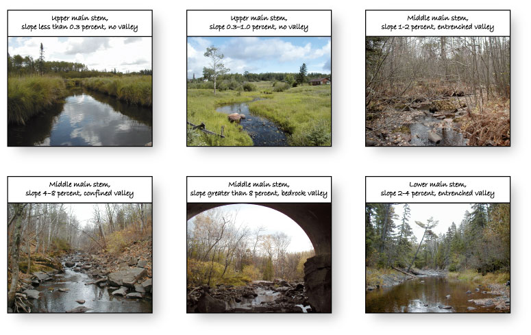
Geomorphic Segment Classification
Figure 1. Study area and sampling sites in the Duluth, Minn., ar...
Figure 2. Plan view and longitudinal profile of geomorphic zones...
Figure 3. Spatial hierarchy of watershed, stream-segment, and st...
Figure 4. Bedrock geology of the Duluth, Minn., area (from Mille...
Figure 5. Surficial geology and geomorphology of the Duluth, Min...
Figure 6. Land cover in the Duluth, Minn., area (from Minnesota ...
Figure 7. Population density in the Duluth, Minn., area, 1940 to...
Figure 8. Valley development and valley types for Duluth-area st...
Figure 9. Longitudinal profiles of streams in the A , s...
Figure 10. Hierarchical classification of channel types in the D...
Figure 11. Longitudinal profiles for A , Lester River a...
Figure 12. Photographs of rapid assessment sites on tributaries ...
Figure 13. Geomorphic segment classification for Duluth-area str...
Table 1. Land-cover characteristics for Duluth-area watersheds, ...
Table 2. Conditions at the mouths of Duluth-area streams, Minn.
Table 3. Number of stream segments in each slope/drainage-networ...
Table 4. Number of stream segments in each slope/valley type cat...
Table 5. Geomorphic characteristics of stream segments for Dulut...
Table 6. Explanation of abbreviations used in tables for segment...
Table 7. Reach characteristics at rapid assessment and intensive...
Table 8. Potential channel types in each slope/valley category f...
Table 9. Geomorphic segment classification scheme for streams in...
| Multiply | By | To obtain |
|---|---|---|
|
Length
|
||
| inch (in.) | 2.54 | centimeter (cm) |
| foot (ft) | 0.3048 | meter (m) |
|
Area
|
||
| square mile (mi2) | 2.590 | square kilometer (km2 ) |
|
Flow rate
|
||
| cubic foot per second (ft3/s) | 0.02832 | cubic meter per second (m3/s) |
Temperature in degrees Fahrenheit (°F) may be converted to degrees Celsius (°C) as follows:
°C=(°F-32)/1.8
Vertical coordinate information is referenced to the North American Vertical Datum of 1927 (NAVD 27).
Horizontal coordinate information is referenced to the North American Datum of 1983 (NAD 83).
Altitude, as used in this report, refers to distance above the vertical datum.
In 2003 and 2004, a geomorphic assessment of streams in 20 watersheds in the Duluth, Minn., area was conducted to identify and summarize geomorphic characteristics, processes, disturbance mechanisms, and potential responses to disturbance. Methods used to assess the streams included watershed characterization, descriptions of segment slopes and valley types, historical aerial photograph interpretation, and rapid field assessments and intensive field surveys of stream reaches. Geomorphic conditions were summarized into a segment-scale classification with 15 categories mainly based on drainage-network position and slope, and, secondarily, based on geologic setting, valley type, and dominant geomorphic processes. Main causes of geomorphic disturbance included historical logging and agriculture, and ongoing urban development, human-caused channel alterations, road and storm sewer drainage, ditching, hiking trails, and gravel pits or quarries. Geomorphic responses to these disturbances are dependent on a combination of drainage-network position, slope, and geologic setting. Geologic setting is related to drainage-network position because the geologic deposits parallel the Lake Superior shoreline. Headwater streams in large watersheds flow over glacial deposits above altitudes of about 1,200 feet (ft). Headwater tributaries and upper main stems have ditch-like channels with gentle slopes and no valleys. Urban development and road drainage cause increased runoff and flood peaks in these segments resulting in channel widening. Below about 1,200 ft, main-stem segments generally are affected by bedrock type and structure and have steep slopes and confined or entrenched valleys. Increases in flood peaks do not cause incision or widening in the bedrock-controlled valleys; instead, the flow and scour areas are expanded. Feeder tributaries to these main stems have steep, confined valleys and may be sources for sediment from urban areas, road runoff, or storm sewer outfalls. Main-stem segments near the glacial deposits/surficial bedrock contact (1,000–1,200 ft) have the most potential for response to disturbance because they tend to have narrow valleys with sandy glacial lakeshore deposits and moderate slopes. Increases in flood peaks (from upstream increases in runoff) increase the potential for landslides and mass wasting from valley sides as well as channel widening.
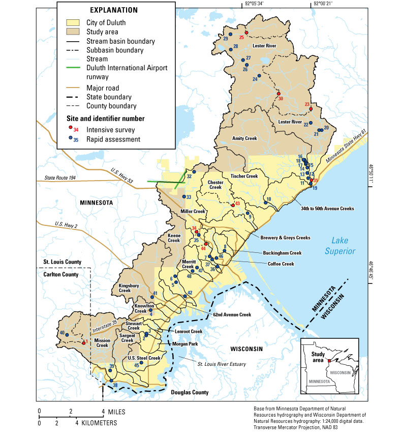
Streams in the Duluth, Minn., area (fig. 1) have been affected by a variety of historical land uses but remain highly valued for their natural resources. Streams and riparian areas contain important habitat for endangered or threatened aquatic and terrestrial species. Understanding the geomorphic conditions and processes of streams within a stream network or watershed framework is important because they relate to the overall water and aquatic resource quality of the stream and to the plant and animal communities and habitat adjacent to the stream. In 2003–2004, the U.S. Geological Survey (USGS), in cooperation with the city of Duluth, studied the geomorphic characteristics and processes that affect the physical conditions of Duluth-area streams.
The Duluth Natural Areas Program (DNAP) is based on a city ordinance designed to protect and preserve the natural heritage of Duluth and the surrounding area. The program strives to protect plant and animal communities, habitat for special species, natural water features, important bird habitat areas, and landscapes. Data on stream geomorphic conditions provide a basis for evaluating the rarity and quality of natural resources nominated to DNAP for their natural water features. An assessment of geomorphic conditions within the stream channels is important for understanding the extent to which natural factors and land-use changes have affected geomorphic attributes, such as bed and channel configurations, and the likelihood that geomorphic conditions may change in the future.
A thorough stream geomorphic assessment includes a description of how channel, flood-plain, and valley landforms are spatially and temporally affected by regional and local geology, topography, climate, vegetative cover, and human modifications. Stream networks developed in homogeneous geologic deposits commonly consist of an erosion zone (where sediment and runoff are generated), a transition zone (were sediment and water are transferred through with no net gain or loss of material), and a deposition zone (where sediment from upstream erosion is dropped out of transport) (Schumm, 1977). A typical longitudinal profile of a stream illustrates how the slope of a stream typically changes from relatively steep in the erosion zone near its headwaters to gentle in the depositional zone near its mouth (Hack, 1960) (fig. 2). An understanding of sediment sources, transport, and deposition and their links to stream network position is key to understanding geomorphic responses to present and future disturbances.
Three common spatial scales used to identify geomorphic characteristics and processes are a watershed or landscape scale, a segment scale, and a reach or channel scale (fig. 3). The segment scale is a section of stream bounded by confluences or physical or chemical discontinuities, such as major landforms, changes in slope, or point-source discharges. The reach scale is a length of stream chosen to illustrate a set of uniform channel features and represents the typical sampling unit used for field-based measurements of geomorphic characteristics. Reach-scale geomorphic conditions and processes can be used to infer conditions and processes for a given segment.
A hierarchical channel classification system, based on geomorphic processes, was developed for mountain streams in the Pacific Northwest to help interpret channel morphology, assess geomorphic conditions, and predict responses to natural and human-caused disturbance (Montgomery and Buffington, 1993; 1997). In the Montgomery and Buffington (1997) classification, valleys were classified into three major types based on the predominant geologic materials in the valley—colluvial, bedrock, and alluvial (confined, moderately confined, and unconfined, respectively). Colluvial deposits mainly originate from landslides and mass wasting, whereas alluvial deposits are from transport and depositional processes related to modern rivers. Channels were classified into seven types—colluvial, bedrock, cascade, step-pool, plane-bed, pool-riffle, and dune-ripple. The channel types can be related to drainage-network position, underlying geology, and slope. The Montgomery and Buffington (1993; 1997) classification is not commonly used in the Midwest because streams have relatively gentle slopes compared to mountain streams. However, tributaries along the north shore of Lake Superior drain bedrock bluff areas and have slopes that exceed 8 percent along some reaches. Bohle (2002) developed a modified version of this classification to assess geomorphic conditions for streams along the north shore of Lake Superior in Minnesota. Bohle (2002) classified stream segments into eight geomorphic map units (GMUs)—boulder/bedrock, main-stem boulder rapid, gravel-dominated pool-riffle, forced pool-riffle plane-bed, large woody debris/boulder step, tributary boulder plane-bed or rapid, beaver dam step-pool, and lacustrine/riverine wetland.
The major objectives of the present geomorphic study of Duluth-area streams are to describe geomorphic characteristics, identify major geomorphic processes and factors contributing to geomorphic characteristics, identify historical changes in channel morphology and planform (plan view of the channel pattern), and develop a segment-scale classification based on similar geomorphic characteristics, processes, and responses to disturbance. The assessment and classification will provide baseline conditions and can be used as a tool for evaluating the quality of Duluth's natural water features. Scientists, city managers, and citizens involved in the Duluth Natural Areas Program can use results from this study to help protect, preserve, and restore resources and help guide management activities. In addition to its social and conservation benefits, this study will advance the understanding of present and historical geomorphic conditions of Duluth-area streams, of other north- and south-shore tributaries to Lake Superior, and of other streams in similar hydrologic settings.
The purpose of this report is to provide an assessment and classification of the geomorphic characteristics, processes, and responses to disturbances of streams in the vicinity of Duluth, Minnesota. The scope of this report includes: 1) description of the current geomorphic characteristics, 2) identification of major geomorphic processes, 3) identification of factors contributing to current geomorphic characteristics and expected future trends in characteristics, 4) interpretations of historical changes in channel morphology and planform, and 5) development of a segment-scale classification based on geomorphic processes. Geomorphic characterizations and the classification system were based on watershed-, segment-, and reach-scale measurements and observations collected in 2003 and 2004.
Any attempt to classify the myriad geomorphic characteristics and processes that can occur in urbanizing or urban streams with disturbed watersheds that have been altered by land clearing, channelization, and ditching into discrete categories will have limitations and problems. Therefore, the main goal of the classification portion of the study, for use with Duluth-area streams only, is to help show the importance of linking geomorphic characteristics and processes of a specific reach of stream in the context of its position within the landscape and geologic setting.
Streams in the Duluth area generally flow perpendicular to the shoreline of Lake Superior, from northwest to southeast (fig. 1). Altitudes of watersheds range from 1,400 ft (above NAVD 27) in the headwaters to 602 ft at Lake Superior. Most of the altitude change occurs along the middle and lower main stems as streams flow over bedrock bluffs and outcrops near the shore of Lake Superior.
The climate of the Duluth area is characterized by cold snowy winters, cool or moderately warm summers, and evenly distributed precipitation (Eichenlaub, 1979). Large variations from average weather can occur because of the proximity of Duluth to Lake Superior. Average annual precipitation is 29–30 in., with 18 in. of average annual evapotranspiration and 10–12 in. of runoff (Young and Skinner, 1974). Mean daily maximum air temperatures range from 22o F in January to 78oF in July (Eichenlaub, 1979).
Bedrock is near or at the land surface in the Duluth area and mainly consists of Proterozoic volcanic and igneous rocks, intrusions, and sedimentary rocks (Miller and others, 2002) (fig. 4). Nomenclature for geologic names of bedrock units follows that of the Minnesota Geological Survey. Bedrock type and faulting affects the pattern and density of the stream networks. Right-angle bends in the channel and stream confluences are indicative of underlying contacts between bedrock units or faulting. The Duluth Complex and miscellaneous other intrusive rocks form a prominent steep rocky bluff that parallels the shoreline of the St. Louis River Estuary and Lake Superior.
Figure 4. Bedrock geology of the Duluth, Minn., area (from Miller and others, 2002).
Quaternary surficial deposits in the Duluth area are generally in the upper parts of most of the watersheds but thin or absent from the middle main stems where bedrock is exposed at the land surface (fig. 5). Glacial deposits in the watersheds are from the Late Wisconsinan Lake Superior Lobe (Goebel and others, 1983). Glacial deposits in the headwaters and the upper parts of the watersheds above about 1,200 ft consist of supraglacial drift composed of sandy loamy till of the Cromwell Formation (Goebel and others, 1983; University of Minnesota–Duluth Geology Department and others, 1997; Hobbs, 2004). Later glacial readvances resulted in the deposition of silty loam till of the Lakewood Member, clay loam to silty clay loam till of the Moose Lake Member, and clay till of the informally named Knife River member, all of the Barnum Formation (Hobbs, 2004). In the Duluth area, the Lakewood Member is at altitudes from about 1,150 to 1,200 ft. The Moose Lake Member is at altitudes from about 1,100 to 1,150 ft. The Knife River member is at altitudes up to about 1,050 ft. Shoreline features from wave action and beaches are present from about 1,020 to 1,100 ft and were caused by multiple phases of a glacial lake in the southwest part of Lake Superior during glacial retreats in the Late Wisconsinan and early Holocene (Leverett, 1929; Hobbs, 2004).
Land cover in the Duluth area consists of a mix of mainly urban land (developed/barren), forest, and shrub (Minnesota Department of Natural Resources, Division of Forestry, 2002) (fig. 6). Urban land is concentrated in Duluth and along transportation corridors leading into Duluth (fig. 1). Categories of marsh, lowland shrub, and lowland forest are in wetland settings.
Population density in 2000 for the area surrounding the studied streams ranged from greater than 5,000 people/mi2 near the center of Duluth to less than 250 people/mi2 in rural areas (U.S. Census Bureau, 2000) (fig. 7). Comparison of population density maps for 1940, 1960, 1980, and 2000 shows how urban development has spread through the watershed of Miller Creek and along the shore of Lake Superior north of Duluth over the last 20 years (U.S. Census Bureau, 2000; Van Riper, unpublished data).
The methods used to assess the geomorphic characteristics of Duluth-area streams consisted of a variety of techniques that included data collection and interpretation at watershed, segment, and reach scales.
Drainage boundaries were delineated for the 20 studied watersheds and also for subwatersheds of nine intensive survey sites to examine differences among watershed characteristics. Digital drainage boundaries from the USGS (Minnesota Water Science Center, written commun., 2003) were used and (or) updated based on visual interpretations from USGS 7.5-minute topographic maps. Drainage boundaries were overlaid with thematic maps of bedrock geology (Miller and others, 2002) (fig. 4), Quaternary deposits (University of Minnesota–Duluth Geology Department and others, 1997) (fig. 5), and land cover (Minnesota Department of Natural Resources, Division of Forestry, 2002) (fig. 6) by use of a geographic information system (GIS). These overlays were used to summarize differences among the watersheds for geologic setting and land cover (mainly the amount of urbanization).
Longitudinal profiles were constructed for 15 main-stem streams. Stream lengths were measured with a map measurer between contour lines on USGS 7.5-minute topographic maps. Longitudinal profiles are used to identify changes in slope that are related to geologic features or spatial position within the stream network.
Streams were first divided into segments with similar slope and valley confinement, similar to methods described in Montgomery and Buffington (1998). Slope and valley confinement characterizations initially were based on measurements and observations from USGS 7.5-minute topographic maps. Each segment was assigned a unique identification code. Segments were categorized by slope: less than 0.3 percent, 0.3 to 1 percent, greater than 1 to 2 percent, greater than 2 to 4 percent, greater than 4 to 8 percent, or greater than 8 percent. Each segment was classified as confined (valley width less than 2 times the channel width), moderately confined (valley width between 2 and 4 times the channel width), or unconfined (valley width greater than 4 times the channel width). Valley confinement was difficult to estimate from topographic maps; these initial characterizations were confirmed during the reach field surveys and changed, if necessary. Channel-segment boundaries also were confirmed in the field and changed if necessary.
After the field assessments were done, it was determined that valleys in the Duluth area fit into four groups based on modified categories assigned to valleys for Lake Superior tributaries in the western part of the Upper Peninsula of Michigan (Hack, 1965) (fig. 8). Headwater streams in the upstream parts of the watersheds have no valleys, are unconfined (N), and flow over glacial deposits. As drainage area increases and altitude decreases, the stream valleys are confined (C) V-shaped valleys as they cut through the steep, post-glacial shoreline areas, faults, or bedrock. Continuing downstream, the valleys become well developed but stream meanders follow the valley meanders (E). This type of valley and stream meander pattern was called "entrenched" by Hack (1965). The stream-meander pattern for this valley type tends to be irregular and determined by the intersection of the stream and valley with bedrock outcrops, post-glacial lake shorelines, or glacial meltwater valleys. In entrenched valleys, channels commonly intersect valley sides, which combined with enough flow and shear stress, can cause bluff and terrace erosion. Near the mouths, valleys tend to be wide and unconfined and stream-meander patterns are alluvial (A). The valleys are wider than the meander belt and alluvial stream meanders typically are a reflection of fluvial processes of runoff and sediment transport conditions.
Figure 8. Valley development and valley types for Duluth-area streams, Minn.
Aerial photographs from 1939–40, 1956, 1997, and 2002 were used to compare historical and current channel and riparian conditions for the stream segments. Channel width, canopy pattern, type and size of riparian vegetation on each stream bank, stability and position of gravel bars, location of eroding banks, wood loading, and channel position were noted. Riparian vegetation composition was described as deciduous (greater than 70 percent deciduous), coniferous (greater than 70 percent coniferous) or mixed. Riparian vegetation age was described as young (less than 10 years old), mature (between 10 and 40 years old), or old (greater than 40 years old). Riparian vegetation density was described as sparse (greater than 50 percent open ground) or dense (greater than 50 percent forested).
Drainage-network position was assigned to each segment based on the longitudinal profiles and 7.5-minute topographic maps. Main stems were divided into upper, middle, and lower categories, corresponding to main-stem length. Tributary categories were assigned based on the category assignment of the main stem at their confluence.
Predominant categories of bedrock type, glacial landforms/deposits, and land cover were assigned to each segment based on the thematic overlays (Miller and others, 2002; University of Minnesota–Duluth Geology Department and others, 1997; Minnesota Department of Natural Resources, Division of Forestry, 2002; respectively). Bedrock types included sedimentary, gabbro rocks, felsic and mafic volcanic rocks, intrusions, and bedrock buried by glacial deposits. In addition to thematic overlay of bedrock geology from Miller and others (2002), bedrock types along segments were visually checked by use of the non-digital 1:24,000-scale maps of bedrock types and outcrops in Schwartz (1949). Glacial landform/deposits categories were supraglacial drift, outwash, ice-contact, glacial lake, post-glacial shoreline/beach, bedrock surface, till plain, and undifferentiated. Dominant land cover included urban, developing urban, agriculture, forest, wetland, grass, shrubland, and roads.
Rapid assessments of geomorphic characteristics and processes (mainly observation-based) were done at 48 sites from July 2003 through May 2004 (fig. 1). These sites were on segments with a range in slope and valley type. Rapid assessments were based on qualitative and quantitative field methods described in Thorne (1998) for identifying geomorphic characteristics and processes of streams for multi-disciplinary reconnaissance studies. Thorne's (1998) field methods include observations and measurements of riparian vegetation and geology, valley and flood-plain characteristics, and channel characteristics in relation to valley conditions. Channel morphology, bar formation, substrate, and controls on incision and lateral migration were measured and described. Bank conditions and interpretations also were measured and described. Descriptions also included type of road crossing, potential fish-passage problems through culverts, and any other potential local effects to the stream channel. Culverts are common in Duluth-area streams, and if inappropriately constructed, can be obstructions to fish migration (Gibson and others, 2005). Photographs of the streams were taken during the rapid assessments. Rapid assessment data were used to compare observed characteristics to predictions of dominant geomorphic channel processes based on the geomorphic segment classification.
Intensive field surveys were done at nine sites in July, August, and October 2003. These were a subset of sites where rapid field assessments were done (fig. 1). The most common slope and valley types were selected. In addition, sites were concentrated in three watersheds—Mission Creek, Miller Creek, and Lester River—to describe how geomorphic characteristics and processes changed along the longitudinal profiles and also to identify upstream to downstream linkages in geomorphic processes. Assessments included qualitative and quantitative geomorphic assessment of valley, channel, and bank conditions; channel cross-section surveys, substrate measurements, cores of overbank sediment, and measurements of large woody debris (LWD) and pool area. Channel and bank measurements were based on reach-scale descriptions. Reach lengths were based on spacing of riffles, steps, or bedrock falls and ranged from 85 to 273 ft with an average reach length of 170 ft. Channel types were identified as bedrock, colluvial, cascade, step-pool, pool-riffle, plane-bed, or wetland based on definitions from Montgomery and Buffington (1998).
Two channel cross sections were surveyed at each intensive site with an automatic level (Harrelson and others, 1994). A global positioning system was used to verify the location of each cross section. Semi-permanent benchmarks (rebar stakes) were established at each cross section. The cross sections were in riffles. Water-surface and channel slope were measured along the stream distance between the two cross sections.
Quantitative measurements of coarse substrate size in riffles were made by means of Wolman pebble counts (Wolman, 1954). One riffle was chosen (out of the two with cross-section surveys) to conduct the survey. Pebble selection techniques followed Fitzpatrick and others (1998) and the diameter of the b-axis of 100 pebbles were measured and recorded in a field book. If sand or smaller-sized particles were encountered, these particles were tallied as "sand" or "fines".
Overbank sedimentation was measured through exploratory coring with a hand-held soil probe and all cores were described for texture and color in the field by use of the U.S. Department of Agriculture textural triangle and color chart (Munsell Color, 1975; Soil Survey Staff, 1951). Field grading of texture was done by rubbing soil between the fingers (Milfred and others, 1967). Photographs were taken in each reach.
The number, length, and average diameter of woody debris were measured in each reach. Geomorphic function and source for the wood were recorded. Possible functions included pool scour, bank stability, bar stabilizer, sediment trap, or step former. Possible sources for the wood included side slope, upstream, or bank. All wood within the bankfull channel was measured that was larger than 0.1 ft in diameter and 1 ft in length. There is no minimum size standard for LWD. The relatively small minimum size of wood counted in this study (as compared to other studies) was selected to maximize options for comparing LWD in Duluth streams to LWD surveys from other sources.
The area and depth of pools were measured in each reach. Pools were identified by having relatively deep, slow-moving water, and fine-grained bed material compared to the rest of the reach. Pool function also was recorded and included free, LWD, or bedrock/boulder/bank forced.
Channel widths recorded in Government Land Office (GLO) Survey notes from the Duluth area (1857, 1858, 1868, and 1870) were compared to channel and wetted widths measured in cross-section surveys in 2003 to quantify potential channel-width changes at intensive sites. In the GLO surveys, channel widths at section line crossings were measured in links, and 1 link is equivalent to 0.66 ft. It is best to compare GLO surveyed widths at multiple-section line crossings to obtain a sense of data accuracy. For this study, it was assumed that changes greater than +3 ft were appreciable.
The segment-scale classification developed for Duluth-area streams was based in part on Montgomery and Buffington's (1998) classification. Segments were grouped into 15 categories based on drainage-network position, slope, geologic setting (including a combination of bedrock and glacial landform features), valley type, dominant geomorphic processes, and potential responses to disturbance. The classification was based on results from the rapid field assessments and intensive field surveys. Channel types, geomorphic processes, and interpretations of sensitivity to disturbance summarized from the reach data were extrapolated to other segments with similar drainage-network position, slope, geologic setting, and disturbance mechanisms. Interpretations of potential for geomorphic change due to disturbance are based on observations and evidence for historical geomorphic change as well broad assumptions about the effects of slope and parent material on geomorphic processes.
Geomorphic characteristics of Duluth-area streams and the processes responsible for them are determined by topography and slope, drainage-network position, geologic setting (watershed, segment, and reach scales), valley type, base-level controls, vegetation, and human-caused alterations and disturbance. Current (2005) geomorphic processes reflect short- and long-term responses to disturbances. The source for the disturbance may be upstream or downstream of a particular segment or reach of interest.
Watershed characteristics help to determine the amount and timing of runoff and sediment from uplands to channels. The 20 studied watersheds are generally small and range in size from less than 1 mi2 (Lenroot Creek) to 36 mi2 (Lester River) (fig. 1; table 1). All of the streams are underlain by igneous rocks except Mission Creek (fig. 4). Bedrock crops out at the land surface through much of the watersheds but is buried by glacial deposits in the upper parts of the larger watersheds (fig. 5). There is little infiltration and potential for runoff is high where bedrock crops out or is thinly covered by glacial deposits. The Duluth Gabbro complex underlies many of the streams from Stewart Creek northeast to the upper watershed of Tischer Creek. Lester River and Amity Creek are underlain by felsic and mafic volcanic units interspersed with gabbro and mafic intrusions. These bedrock units have different rates of erosion. The sedimentary rocks that underlie the Mission Creek watershed are less resistant to erosion than the volcanics, gabbro complex, or the intrusions. Thus, the Mission Creek drainage pattern is denser and more dendritic than patterns for the other watersheds.
[<, less than]
| Watershed | Drainage area (square miles) | Developed/barren (urban) (percent) | Cropland (percent) | Grassland (percent) | Upland forest (percent) | Lowland forest (percent) | Upland shrub (percent) | Lowland shrub (percent) | Marsh (percent) | Water (percent) |
|---|---|---|---|---|---|---|---|---|---|---|
| Mission Creek | 10.6 | 21 | 4 | 2 | 10 | 46 | 3 | 12 | 1 | <1 |
| Sargent Creek | 3.1 | 11 | 1 | 1 | 31 | 46 | 1 | 9 | <1 | 0 |
| U.S. Steel Creek | 2.8 | 34 | 3 | 3 | 22 | 16 | <1 | 19 | 2 | 0 |
| Morgan Park Creek | 1.3 | 24 | 1 | 1 | 43 | 19 | 0 | 13 | 0 | 0 |
| Stewart Creek | 1.5 | 16 | 1 | 1 | 47 | 25 | 1 | 9 | <1 | 0 |
| Lenroot Creek | .4 | 17 | <1 | 1 | 62 | 6 | 0 | 15 | 0 | 0 |
| Knowlton Creek | 2.2 | 31 | 3 | 2 | 24 | 18 | 5 | 17 | <1 | 0 |
| Kingsbury Creek | 9.0 | 34 | 2 | 1 | 8 | 27 | 8 | 19 | 1 | <1 |
| 62nd Avenue Creek | 1.2 | 45 | 1 | 2 | 13 | 14 | 1 | 24 | 1 | 0 |
| Keene Creek | 6.0 | 30 | 1 | 2 | 11 | 32 | 6 | 18 | <1 | 0 |
| Merritt Creek | 2.2 | 38 | 1 | 1 | 19 | 24 | 1 | 16 | <1 | 0 |
| Miller Creek | 9.3 | 60 | <1 | 1 | 3 | 21 | 6 | 8 | <1 | <1 |
| Buckingham Creek | 1.1 | 54 | 0 | 1 | 17 | 19 | <1 | 8 | <1 | 0 |
| Coffee Creek | 1.6 | 66 | 1 | 0 | 8 | 20 | <1 | 4 | 0 | 0 |
| Brewery and Greys Creeks | 3.0 | 75 | <1 | 0 | 6 | 16 | <1 | 3 | 0 | 0 |
| Chester Creek | 6.7 | 33 | 1 | 1 | 9 | 36 | 7 | 12 | 1 | <1 |
| Tischer Creek | 7.3 | 34 | <1 | 3 | 11 | 44 | 2 | 5 | <1 | <1 |
| 34th to 50th Ave. Creeks | 3.6 | 80 | <1 | <1 | 5 | 11 | <1 | 2 | <1 | <1 |
| Amity Creek | 16.7 | 7 | 2 | 9 | 7 | 69 | 1 | 5 | <1 | <1 |
| Lester River | 36.0 | 3 | 2 | 5 | 7 | 68 | 2 | 11 | <1 | 1 |
Land cover in the studied watersheds is predominantly composed of urban land (developed/barren), forest, or shrub (fig. 6, table 1). Percentages of urban land range from 3 percent in the Lester River watershed to 80 percent in the 34th to 50th Ave. Creeks watershed. Urban land is most concentrated near the mouths along the shoreline of the St. Louis River estuary and Lake Superior; however, urban land extends throughout many of the watersheds, especially those that are bisected by major transportation corridors along U.S. State Highway 53, U.S. Interstate 35, and U.S. State Highway 2 (figs. 1 and 6). Urban watersheds have higher potential for increased runoff rates and volumes and for changes in sediment inputs compared to forested watersheds. Watersheds with more than 50 percent urban land include Miller Creek, Coffee Creek, Buckingham Creek, Brewery and Greys Creeks, and 34th to 50th Ave. Creeks. Seven urban streams near downtown Duluth run underground at their mouths (table 2). Watersheds that are predominantly forest include Mission Creek, Sargent Creek, Morgan Park Creek, Stewart Creek, Lenroot Creek, Amity Creek, and Lester River (table 1). Watersheds that have had noticeable urban development from 1980 to 2000 include Mission Creek, Morgan Park Creek, Stewart Creek, Lenroot Creek, Miller Creek, and Lester River (fig. 7). Geomorphic effects from urban development are concerns for Miller Creek, Chester Creek, and Amity Creek (Camp Dresser and McKee, Inc., 2000).
Table 2. Conditions at the mouths of Duluth-area streams, Minn.
| Stream | Conditions |
|---|---|
| Mission Creek | Channel open to the St. Louis River |
| Sargent Creek | Channel open to the St. Louis River estuary |
| U.S. Steel Creek | Channel open to the St. Louis River estuary |
| Morgan Park Creek | Channel open to the St. Louis River estuary |
| Stewart Creek | Channel open to the St. Louis River estuary |
| Lenroot Creek | Channel open to the St. Louis River estuary |
| Knowlton Creek | Channel open to the St. Louis River estuary |
| Kingsbury Creek | Channel open to the St. Louis River estuary |
| 62nd Ave. Creek | Runs underground by Grand Ave. |
| Keene Creek | Channel open to the St. Louis River estuary |
| Merritt Creek | Channel open to the St. Louis River estuary |
| Miller Creek | Runs underground through downtown Duluth |
| Buckingham Creek | Runs underground through downtown Duluth |
| Coffee Creek | Runs underground through downtown Duluth |
| Brewery and Greys Creeks | Runs underground through downtown Duluth |
| Chester Creek | Runs underground in downtown Duluth |
| Tischer Creek | Channel open to Lake Superior |
| 34th to 50th Ave. Creeks | Some channels open, others run underground |
| Amity Creek | Channel open to Lake Superior |
| Lester River | Channel open to Lake Superior |
Duluth-area main stems have complex longitudinal profiles (fig. 9) that are very different from the typical longitudinal profile shown in figure 2 for geologically old landscapes with homogeneous geologic deposits. Irregularities in the Duluth stream profiles are attributed to differences in the erodibility of geologic materials, extent of landforms, or changes in base level (Hack, 1965). Specifically, Duluth area longitudinal profiles reflect bedrock type and distribution of fault zones, variations in the texture of glacial deposits, glacial landforms (such as moraines and outwash plains), postglacial landforms from beach ridges, shorelines or melt-water valleys, and the present level of Lake Superior. Reaches with steep slopes are prone to long-term erosional conditions, whereas reaches with gentle slopes are prone to long-term depositional conditions (Knighton, 1998). Reaches in a transition from steep to gentle slopes may change from erosional to depositional if upstream inputs of water and sediment change.
The upper main stems tend to have gentle slopes for headwaters in glacial deposits at altitudes higher than about 1,200 ft. Irregularities in the longitudinal profiles are common from about 1,200 to 1,000 ft because of the boundary among glacial deposits, bedrock, and glacial lake shorelines. The steep slopes are on middle and lower main stems and tributaries indicate where the streams intersect bedrock (fig. 4). Streams flowing over the Duluth Complex gabbro intrusions have the steepest slopes. Below 1,100 ft, longitudinal profiles for Mission Creek and Sargent Creek are concave upward and less steep than streams to the northeast because Mission and Sargent Creek intersect the less resistant Animikie sedimentary rocks and glacial lake plain. In the northeastern part of the city, Lester River, Amity Creek, and a portion of Tischer Creek have more gentle slopes than streams in the center of the city but steeper slopes than Mission and Sargent Creeks because the streams intersect Keweenawan volcanic rocks. Only a few streams in the southwestern part of the study area have enough length on till plain or built-out land to have a gentle slope near their mouths in the St. Louis River estuary (fig. 1).
Streams with gentle slopes (less than 0.3 percent) generally were headwater streams flowing on glacial deposits with no valley development with wetland vegetation (lowland shrub or forest); whereas streams with moderate to steep slopes flowed on bedrock and had confined or entrenched valleys (tables 3 and 4). Alluvial valleys were rare because of the small watershed sizes, bedrock control, and geologically young age of the streams (less than 10,000 years). Main-stem segments with moderate slopes typically were in the boundary zone between glacial deposits and bedrock. Tributaries to middle or lower main stems most commonly had 2–8 percent slopes in confined valleys. The combination of steep slopes and confined or entrenched valleys are indicative of a high potential for landslides along valley sides, especially if sandy glacial lake shoreline deposits are present. If valley sides are made up of unconsolidated deposits, the potential for landslides, mass wasting, and channel erosion increases if runoff and flood peaks increase (Fitzpatrick and others, 1999).
[<, less than; >, greater than]
| Slope category (percent) | Upper main stem | Middle main stem | Lower main stem | Upper tributary | Middle tributary | Lower tributary | Total |
|---|---|---|---|---|---|---|---|
| <0.3 | 4 | 0 | 0 | 3 | 0 | 0 | 7 |
| 0.3-1 | 10 | 7 | 8 | 5 | 4 | 1 | 35 |
| >1-2 | 4 | 19 | 6 | 3 | 9 | 1 | 42 |
| >2-4 | 7 | 6 | 10 | 6 | 15 | 10 | 54 |
| >4-8 | 2 | 4 | 9 | 3 | 3 | 10 | 31 |
| >8 | 1 | 7 | 7 | 1 | 2 | 1 | 19 |
| Total | 28 | 43 | 40 | 21 | 33 | 23 | 188 |
Table 4. Number of stream segments in each slope/valley type category for Duluth-area streams, Minn.
[<, less than; >, greater than]
| Slope category (percent) | No valley | Confined (origin not determined) | Entrenched | Alluvial | Bedrock (confined) | Total |
|---|---|---|---|---|---|---|
| <0.3 | 7 | 0 | 0 | 0 | 0 | 7 |
| 0.3-1 | 26 | 1 | 4 | 4 | 0 | 35 |
| >1-2 | 17 | 10 | 12 | 0 | 3 | 42 |
| >2-4 | 1 | 37 | 10 | 1 | 5 | 54 |
| >4-8 | 0 | 15 | 8 | 0 | 8 | 31 |
| >8 | 0 | 0 | 9 | 0 | 10 | 19 |
| Total | 51 | 63 | 43 | 5 | 26 | 188 |
Characteristics for all the segments are listed in table 5, with a list of abbreviations and definitions in table 6. Drainage-network position, slope, valley type, bedrock type, glacial landform, and dominant land cover are described in table 5. The table has site identification numbers for segments with rapid assessment or intensive survey sites. Based on field reach-scale data and air photos, characteristics of channel type, dominant substrate, mode of sediment transport, flood attenuation, observed/expected causes for disturbance, presence of storm drains, and potential for geomorphic change are described for segments with field sites and extrapolated for other segments. Almost all of the segments have one or more observed or expected causes for disturbance, usually land clearing, urban development, road drainage, and inputs from upstream segments. The only exception is six tributary segments near the middle/lower main stem of Mission Creek that have complete forest cover and no roads.
Table 5. Geomorphic characteristics of stream segments for Duluth-area streams, Minn., 2003–2004.
[See table 6 for explanation of abbreviations. Stream segments are shown on figure 13. Data in
italics
are extrapolated from reach assessments of sites with the same segment category. Data in
bold
are rapid assessment or intensive survey sites. USGS, U.S. Geological Survey; ID, identification number; --, no detailed measurements taken; %, percent; >, greater than; <, less than]
Table is large; scroll down and to the right to view entire table.
| Segment ID | Stream name | Topographic map | USGS reach ID | Drainage-network position | Slope % | Valley type | Bedrock type | Glacial landform | Dominant land cover | Inter- mittent | Segment ID | Channel type | Dominant substrate | Mode of sediment transport | Flood attenuation | Dominant geomorphic processes | Observed/expected causes for disturbance | Storm-drain outfalls | Potential geomorphic changes | Sensitivity to disturbance | Geomorphic segment category | Segment ID |
|---|---|---|---|---|---|---|---|---|---|---|---|---|---|---|---|---|---|---|---|---|---|---|
| b1 | Buckingham Creek | Duluth | -- | LM | >8 | E | GAB | BED | U | N | b1 | BE | BE | T, SIp | NO | EX | UP, HI, UR | Y | Y | LO | B | b1 |
| b2 | Buckingham Creek | Duluth Heights | 8 | MM | >1–2 | N | GAB | BED | U | N | b2 | PB | GV | SIa | FP | A | UP, CA, UR, GV, CL | N | Y | MOD | M1 | b2 |
| b3 | Buckingham Creek | Duluth Heights | -- | UT | >2–4 | C | GAB | BED | F | Y | b3 | CO | CO/BO | SOi, SOw | NO | I, W | CL, CA, RO, GV | N | Y | MOD | T2 | b3 |
| c1 | Chester Creek | Duluth | 9 | LM | >4–8 | E | VOL | BED | U | N | c1 | BE | BO/BE | T, SOb | NO | EX, EBL | UP, HI, UR | Y | Y | LO | B | c1 |
| c2 | Chester Creek | Duluth | 43 | MM | >1–2 | N | GAB | OW/BED | U/F | N | c2 | PR/SP | GV | SOi, SOw, T, SIc, SIp | FP | I, EBA, W, LM, BF | UP, UR, RO, CL | Y | Y | HI | M1 | c2 |
| c3 | Chester Creek | Duluth, Duluth Heights | -- | UM | 0.3–1 | N | GAB | SD/BED | S/W | N | c3 | WE | GV | SOw, SOi, T, SIa | WE | I, W, EBA, A | CL, UR, RO, CA | N | Y | MOD | W.3 | c3 |
| c4 | Chester Creek | Duluth | -- | MM | <0.3 | N | BUR/GAB | OW | U | N | c4 | AR | FINES | T, SOw | NO | EBA, LM, W, A | UR, CA, RO, CL | Y | Y | MOD | W | c4 |
| c5 | Chester Creek | Duluth, Duluth Heights | -- | UM | >1–2 | N | GAB | SD | S/U | N | c5 | WE | GV | SOw, SOi | FP | I, W, EBA | CL, UR, RO | Y | Y | HI | U1 | c5 |
| c6 | Chester Creek | Duluth, Duluth Heights | -- | UM | >1–2 | N | GAB | BED | U | N | c6 | AR/PB | CO | SOb, SOi, SOw, T | NO | I, W, EBA, LM | UR, RO, CA, CL | Y | Y | HI | U1 | c6 |
| c7 | Chester Creek | Duluth | -- | LT | >2–4 | C | VOL | BED | F/U | Y | c7 | CO | BO | SOi, SOb, SOw | NO | I, W, EBA, EBL, EX | UR, RO, CL | Y | Y | MOD | LT | c7 |
| k1 | Keene Creek | West Duluth | -- | LM | 0.3–1 | N | GAB | TP | U | N | k1 | AR | BO | T, SIa | NO | A | UP, UR, RO, CA | N | Y | LO | A | k1 |
| k2 | Keene Creek | West Duluth | -- | LM | >2–4 | C | GAB | BED | U | N | k2 | BED/CA | BO | SOb, SOw, T | NO | W, EBA, EBL, EX | UP, RO, UR | Y | Y | MOD | L2 | k2 |
| k2a | Keene Creek | West Duluth | 42 | LM | >1–2 | N | GAB | TP | U | N | k2a | PB/AR | BO | T | NO | ST | UP, UR, RO, CA | Y | Y | LO | L1 | k2a |
| Segment ID | Stream name | Topographic map | USGS reach ID | Drainage-network position | Slope % | Valley type | Bedrock type | Glacial landform | Dominant land cover | Inter- mittent | Segment ID | Channel type | Dominant substrate | Mode of sediment transport | Flood attenuation | Dominant geomorphic processes | Observed/expected causes for disturbance | Storm-drain outfalls | Potential geomorphic changes | Sensitivity to disturbance | Geomorphic segment category | Segment ID |
| k3 | Keene Creek | West Duluth, Duluth Heights | -- | MM | >4–8 | E | GAB | BED | U/F | N | k3 | CA/BE | BO | T, SOw, SOb | NO | W, EX, EBL, EBA | UR, RO, UP, GV, CL | Y | Y | MOD | B | k3 |
| k4 | Keene Creek | Duluth Heights | 6 | MM | >1–2 | E | GAB | BED/SH | F/U | N | k4 | PR/SP | BO/CO | T, SOw, SOi | NO | W, EBA, I, LM | UP, GV, UR, RO, CL | N | Y | HI | M1 | k4 |
| k5 | Keene Creek | Duluth Heights | -- | UM | 0.3–1 | N | GAB | SD/BED | F/U/W | N | k5 | WE | SA/FINES | SOw, SOi, SIa | WE | W, EBA, I, A | UR, RO, GV | N | Y | MOD | W.3 | k5 |
| k6 | Keene Creek trib | Duluth Heights | 5 | MT | >4–8 | B | GAB | BED/SH | U/F | N | k6 | CA/CO | BO | T | NO | EX | UR, RO, GV | N? | Y | MOD | BT | k6 |
| kg1 | Kingsbury Creek | West Duluth | -- | LM | 0.3–1 | A | BUR | TP | U | N | kg1 | AR | BO | T, SIa | NO | ST, A | UP, RO, CL | Y | Y | LO | A | kg1 |
| kg2 | Kingsbury Creek | West Duluth | -- | LM | >4–8 | C | GAB | BED/SH | U | N | kg2 | BE | BE | SOw, SOi, SIc, T | NO | W, EBA, EX, BF | UR, RO, UP | Y | Y | MOD | B | kg2 |
| kg2a | Kingsbury Creek | West Duluth | -- | LM | >2–4 | C | GAB | BED | F/U | N | kg2a | BED/CA | BO/BE | SOw, T | NO | W, EBA, EX, BF | UP, RO, UR | N | Y | LO | L2 | kg2a |
| kg2b | Kingsbury Creek | West Duluth | -- | LM | >4–8 | C | GAB | BED | U | N | kg2b | BE | BE | SOw, T | NO | W, EBA, EX, BF | UR, RO, UP | N | Y | LO | B | kg2b |
| kg2c | Kingsbury Creek | West Duluth | -- | LM | >8 | C | GAB | BED | U | N | kg2c | BE | BE | SOb , SOw, T | NO | EX | UP, UR, RO | Y | Y | LO | B | kg2c |
| kg2d | Kingsbury Creek | West Duluth | -- | LM | >2–4 | C | GAB | BED | U | N | kg2d | BED/CA | BO | SOb , T, SOw, SIc | NO | EX, EBA, W, BF | UP, UR, RO | Y | Y | MOD | L2 | kg2d |
| kg3 | Kingsbury Creek | West Duluth | 41 | MM | >2–4 | B | GAB | SH/SD/BED | U/F | N | kg3 | SP/CA | BO | SOb, SOw, T, SIc | NO | EBL, EBA, LM, BF, W | UP, RO, UR | N | Y | HI | M2 | kg3 |
| kg4 | Kingsbury Creek | West Duluth | -- | MM | 0.3–1 | N | GAB | SD | W/U | N | kg4 | AR | SA/FINES | SOb, T, SOw, SIc | WE | EBA, I, W, A | UP, CA, UR, RO, CL | N | Y | MOD | M.3 | kg4 |
| kg5 | Kingsbury Creek | Duluth Heights | -- | UM | <0.3 | N | GAB | SD/BED | W | N | kg5 | AR/WE | FINES | SOw, T, SIa | WE | EBA, LM, I, A | CA, RO, CL | N | Y | MOD | W | kg5 |
| Segment ID | Stream name | Topographic map | USGS reach ID | Drainage-network position | Slope % | Valley type | Bedrock type | Glacial landform | Dominant land cover | Inter- mittent | Segment ID | Channel type | Dominant substrate | Mode of sediment transport | Flood attenuation | Dominant geomorphic processes | Observed/expected causes for disturbance | Storm-drain outfalls | Potential geomorphic changes | Sensitivity to disturbance | Geomorphic segment category | Segment ID |
| kg6 | Kingsbury Creek | Duluth Heights | -- | UM | 0.3–1 | N | GAB | SD/BED | W | N | kg6 | AR/DW | SA/FINES | SOw, SIa, T | WE | A, I, W | UP, RO, CA, CL | N | Y | LO | W.3 | kg6 |
| kg7 | Kingsbury Creek | Duluth Heights | -- | UT | >1–2 | N | GAB | SD/BED | W | Y | kg7 | PR | CO | SOw, SOi | NO | I | CL, UR, RO | N | Y | MOD/HI | T1 | kg7 |
| kg8 | Kingsbury Creek | Duluth Heights | -- | UT | >4–8 | C | GAB | SD/BED | F/U | Y | kg8 | CO | BO | SOw, SOi | NO | I | UR, RO, CL | N | Y | MOD/HI | BT | kg8 |
| kw1 | Knowlton Creek | West Duluth | -- | LM | 0.3–1 | N | GAB | TP | F/U | N | kw1 | AR | SA/FINES | T, SIa, SOb | FP | A | UP, CA, RO | Y | Y | MOD | A | kw1 |
| kw2 | Knowlton Creek | West Duluth | 4 | MM | >4–8 | E | GAB | BED | U | N | kw2 | BE/CA | BO | T, SOw, SOb | NO | EX, EBL, EBA | UP, RO, UR, CA | N | Y | MOD | B | kw2 |
| kw2a | Knowlton Creek | West Duluth | -- | LM | >8 | E | GAB | BED | F | N | kw2a | BE | BE | T | NO | EX | UP, RO, UR | N | Y | LO | B | kw2a |
| kw2b | Knowlton Creek | West Duluth | -- | MM | >4–8 | E | GAB | BED | U/F | N | kw2b | BE/CA | BO | T | NO | EX | UP, RO, UR | N | Y | LO | B | kw2b |
| kw2c | Knowlton Creek | West Duluth | -- | MM | >8 | E | GAB | BED/SH | S/U | N | kw2c | BE | BE | T | NO | EX | UP, RO, UR | N | Y | LO | B | kw2c |
| kw3 | Knowlton Creek | West Duluth | -- | UM | >1–2 | N | GAB | SD | U | N | kw3 | AR | PB | T, SOw | NO | A | CA, RO, UR | N | Y | HI | U1 | kw3 |
| l1 | Lester River | Duluth, Lakewood | 19, 31 | LM | >2–4 | E | VOL | BED | F | N | l1 | BE | BE | T, SIp | NO | EX, W, BF, EBL | UP, HI | Y | Y | LO | L2 | l1 |
| l10 | Amity Creek | Arnold, Duluth | -- | MM | 0.3–1 | N | GAB | SD | A/F | N | l10 | PR | GV | SOb, SIc | FP | EBA, W, LM, OS, BF | UP | N | Y | MOD/HI | M.3 | l10 |
| l11 | Amity Creek | Arnold, Duluth | -- | MT | >1–2 | N | GAB | SD | AF | N | l11 | PR | GV | SOb | FP | EBA, W, LM, OS, BF | CL | N | Y | MOD/HI | T1 | l11 |
| l12 | Amity Creek | Arnold | -- | MM | >1–2 | N | BUR/GAB | SD | W | N | l12 | PR | GV | Sob, SIb | WE | EBA, W, LM, OS | UP | N | Y | MOD | M1 | l12 |
| Segment ID | Stream name | Topographic map | USGS reach ID | Drainage-network position | Slope % | Valley type | Bedrock type | Glacial landform | Dominant land cover | Inter- mittent | Segment ID | Channel type | Dominant substrate | Mode of sediment transport | Flood attenuation | Dominant geomorphic processes | Observed/expected causes for disturbance | Storm-drain outfalls | Potential geomorphic changes | Sensitivity to disturbance | Geomorphic segment category | Segment ID |
| l13 | Amity Creek | Arnold | -- | UM | <0.3 | N | BUR/GAB | SD | W | N | l13 | WE | FINES | SIa | WE | A | CA | N | Y | LO | W | l13 |
| l14 | Amity Creek | Arnold | -- | UM | 0.3–1 | N | BUR/GAB | SD | WF | N | l14 | WE/PR | FINES | SIa | WE | A | UP, CA, CL | N | Y | LO | W.3 | l14 |
| l15 | Amity Creek | Arnold | -- | UT | >1–2 | C | BUR/GAB | SD | F | N | l15 | PR | GV | SOi, SOw | NO | I, EBA | CL, RO | N | Y | MOD | T1 | l15 |
| l16a | Amity Creek | Arnold | -- | UM | >1–2 | N | BUR/GAB | SD | F/A/W | N | l16a | PR | GV | SOi, SOw | FP/WE | I, EBA | RO, UR, CL | N | Y | HI | U1 | l16a |
| l16b | Lester River | French River, Arnold | -- | MT | >2–4 | C | VOL/IN | SD | F/A | N | l16b | CA | BO | SOi, SOw, SOb | NO | I, EBA, EBL, W, LM, BF | CL, UR, RO | N | Y | HI | T2 | l16b |
| l17 | Amity Creek | Arnold | -- | UT | <0.3 | N | BUR/GAB | SD | W | N | l17 | WE | FINES | SIa | NO | I, EBA | UP, CA | N | Y | LO | W | l17 |
| l18 | Amity Creek | Arnold | -- | UT | >1–2 | N | BUR/GAB | SD | F/W | Y | l18 | PR | GV | SOi, SOw | WE | A | CL | N | Y | MOD | T1 | l18 |
| l19 | Lester River | French River | -- | MM | 0.3–1 | E | IN | TP | F/A | N | l19 | PR | CO/GV | T, SOb, SOw, SIc | NO | EBA, EBL, W, LM, BF | UP, CL, RO | N | Y | MOD | M.3 | l19 |
| l19a | Lester River | French River | 20 | MM | >1–2 | E | VOL/IN | BED | F/A | N | l19a | PB/SP | CO/BO | T, SOb, SOw | NO | EBA, EBL, W, LM, BF | UP, CL, RO | N | Y | MOD | M1 | l19a |
| l2 | Amity Creek | Duluth | 11 | LM | >2–4 | E | VOL | BED | F/U | N | l2 | BE | BE | T, SIp | NO | EX, W | UP, HI | Y | Y | LO | L2 | l2 |
| l20 | Lester River | French River, Arnold | 23 | MM | 0.3–1 | E | BUR/IN | SH | F | N | l20 | PR | GV | T, SOb, SOw | NO | W, EBA, EBL | UP | N | Y | HI | M.3 | l20 |
| l21 | Lester River | French River | 21 | MM | >2–4 | B | IN | BED/SH | F/A | N | l21 | PB | GV | T, SOb | NO | W, EX, EBA | UP, CL, UR, RO | N | Y | MOD | M2 | l21 |
| l22 | Lester River | Arnold | 22 | MM | >1–2 | N | BUR/IN | SD/SH | F | N | l22 | PB | GV | T, SIa | WE | A | UP, CL, UR, RO | N | Y | MOD | M1 | l22 |
| Segment ID | Stream name | Topographic map | USGS reach ID | Drainage-network position | Slope % | Valley type | Bedrock type | Glacial landform | Dominant land cover | Inter- mittent | Segment ID | Channel type | Dominant substrate | Mode of sediment transport | Flood attenuation | Dominant geomorphic processes | Observed/expected causes for disturbance | Storm-drain outfalls | Potential geomorphic changes | Sensitivity to disturbance | Geomorphic segment category | Segment ID |
| l23 | Lester River | Arnold | -- | UT | 0.3–1 | N | BUR/IN | SD | W | N | l23 | WE | FINES | SIa, SIb | WE | A | CL, RO | N | Y | LO | W.3 | l23 |
| l24 | Lester River | Arnold | -- | MT | >2–4 | C | BUR/IN | SD | F/A | N | l24 | PB | BO | SOw, SOi | NO | I, EBA, W | UP, CL, UR | N | Y | MOD | M2 | l24 |
| l25a | Lester River | Arnold | -- | MT | 0.3–1 | N | BUR/IN | SD | W | N | l25a | WE/PR | FINES | SOw, SIa | NO | A | CL, CA, UR | N | Y | LO | W.3 | l25a |
| l25b | Lester River | Arnold | -- | MT | >1–2 | N | BUR/IN | IC | F/A | N | l25b | PB | GV | T, SOw | NO | EBA, W, LM, OS | CL, GV | N | Y | MOD | T1 | l25b |
| l26 | Lester River | Arnold | -- | MT | 0.3–1 | N | BUR/IN | UN | F/A | N | l26 | AR/PR | GV/FINES | T, SOw, SIa | WE | W, EBA | CL, RO, CA, GV | N | Y | MOD | W.3 | l26 |
| l27 | Lester River | Arnold | -- | MT | 0.3–1 | N | BUR/GAB | OW/SD | FW | N | l27 | WE | FINES | SIa | WE | A | CL | N | Y | LO | W.3 | l27 |
| l28 | Lester River | Arnold | 30 | MM | >1–2 | E | IN | IC | AF | N | l28 | PB | CO/BO | SOw, SOb, T | NO | W, EBA, EBL | UP, CL | N | Y | HI | M1 | l28 |
| l29 | Lester River | Arnold | -- | MT | >1–2 | N | IN | SD | W | N | l29 | WE | FINES | SIa | WE | A | CL | N | Y | LO | T1 | l29 |
| l3 | Amity Creek | Duluth | -- | LM | >1–2 | C | IN | BED/SD/SH | F | N | l3 | CA | BO | T, SIc | NO | EX, W, EBL, LM, BF | UP | N | Y | MOD/HI | L1 | l3 |
| l30 | Lester River | Arnold | -- | MT | 0.3–1 | N | IN | SD | W | N | l30 | WE | FINES | SIa | WE | A | UP, CL, CA | N | Y | LO | W.3 | l30 |
| l31 | Lester River | Arnold | -- | MT | 0.3–1 | N | IN | SD | W | N | l31 | WE | FINES | SIa | WE | A | CL, RO | N | Y | LO | W.3 | l31 |
| l32 | Lester River | Arnold | 24 | UM | 0.3–1 | N | BUR/GAB | OW | W/F | N | l32 | PR/PB | CO | SIa | WE | ST | UP, GV, CL | N | Y | MOD | W.3 | l32 |
| l33 | Lester River | Arnold | UT | 0.3–1 | N | BUR/GAB | SD | W/F | N | l33 | WE | FINES | SIa | WE | ST | RO, UR, CL | N | Y | MOD | W.3 | l33 | |
| Segment ID | Stream name | Topographic map | USGS reach ID | Drainage-network position | Slope % | Valley type | Bedrock type | Glacial landform | Dominant land cover | Inter- mittent | Segment ID | Channel type | Dominant substrate | Mode of sediment transport | Flood attenuation | Dominant geomorphic processes | Observed/expected causes for disturbance | Storm-drain outfalls | Potential geomorphic changes | Sensitivity to disturbance | Geomorphic segment category | Segment ID |
| l34 | Lester River | Arnold | 25, 26, 27, 28, 29 | UM | <0.3 | N | BUR/GAB | SD | W/F | N | l34 | WE | FINES | SOi, SIa | WE | I, W, EBA, A | RO, UR, CL | N | Y | LO | W | l34 |
| l35 | Lester River | Arnold | -- | UT | <0.3 | N | BUR/GAB | SD | W | N | l35 | WE | FINES | SIa | WE | I, W, EBA, A | UR | N | Y | LO | W | l35 |
| l36 | Lester River | Arnold | -- | UT | <0.3 | N | BUR/GAB | SD | W | N | l36 | WE | FINES | SOi, SIa | WE | I, W, EBA, A | UR, GV | N | Y | LO | W | l36 |
| l37 | Lester River | Duluth | -- | LT | >4–8 | C/E | IN | BED | F | Y | l37 | CO/BE | BO/BE | T, SOw | NO | W, EX | CL, UR, RO | N | Y | MOD | BT | l37 |
| l38 | Amity Creek | Duluth | -- | LT | >2–4 | C | IN | SD | F/A | Y | l38 | CO | CO | SOi, SOw, SOb | NO | I, EBL, EBA | CL | N | Y | HI | LT | l38 |
| l39 | Amity Creek | Duluth | -- | LT | >2–4 | C | IN | SD | F/U | Y | l39 | CO | CO | SOi, SOw, SOb | NO | I, EBL, EBA | CL | N | Y | HI | LT | l39 |
| l3a | Amity Creek | Duluth | 12, 13, 14, 15, 16 | LM | >1–2 | E | VOL | BED | F | N | l3a | PB/BE | BO/BE | T, SIc | NO | EX, W | UP, HI | N | Y | LO | L1 | l3a |
| L3b | Amity Creek | Duluth | 17, 18 | LM | >2–4 | E | IN | BED | F | N | L3b | BE | BE | T, SIp | NO | EX, W | UP, HI | N | Y | LO | L2 | L3b |
| l4 | Amity Creek | Duluth | -- | MM | >1–2 | C | IN | BED/SD | F/A | N | l4 | CA | BO | T, SIc, SOw, SOb | NO | EX, W | UP, HI, RO, CL | N | Y | HI/MOD | M1 | l4 |
| l40 | Amity Creek | Duluth | -- | LT | >4–8 | C | IN | SD | F/A/U | Y | l40 | CO | BO | SOi, SOw, SOc | NO | I, EBL, EBA | CL, UR, RO | N | Y | HI | BT | l40 |
| l41 | Amity Creek | Duluth | -- | LT | >4–8 | C | IN | SD | F/A | Y | l41 | CO | BO | SOi, SOw, SOc | NO | I, EBL, EBA | CL, UR, RO | N | Y | MOD | BT | l41 |
| l42 | Amity Creek | Duluth | -- | LT | >4–8 | C | VOL | BED/TP | F/U | Y | l42 | CO | BO | SOi, SOw, SOc | NO | I, EBL, EBA | UR, RO | Y | Y | MOD | BT | l42 |
| l43 | Amity Creek | Duluth | -- | LT | >4–8 | C | VOL | BED/TP | U/F | Y | l43 | CO | BO | SOi, SOw, SOc | NO | I, EBL, EBA | UR, RO | Y | Y | MOD | BT | l43 |
| Segment ID | Stream name | Topographic map | USGS reach ID | Drainage-network position | Slope % | Valley type | Bedrock type | Glacial landform | Dominant land cover | Inter- mittent | Segment ID | Channel type | Dominant substrate | Mode of sediment transport | Flood attenuation | Dominant geomorphic processes | Observed/expected causes for disturbance | Storm-drain outfalls | Potential geomorphic changes | Sensitivity to disturbance | Geomorphic segment category | Segment ID |
| l44 | Amity Creek | Duluth | -- | LT | >2–4 | C | IN | SD/SH | A | Y | l44 | CO | CO | SOw, SOi | NO | I, EBA, LM | CL, UR, RO | N | Y | MOD/HI | LT | l44 |
| l45 | Amity Creek | Duluth | -- | LT | >2–4 | C | IN | BED/SD/SH | A | Y | l45 | CO | CO | SOw, SOi | NO | I, EBA, LM | CL, UR, RO | N | Y | MOD/HI | LT | l45 |
| l46 | Amity Creek | Duluth | -- | LT | >4–8 | C | IN | BED/SD/SH | A/F | Y | l46 | CO | BO | SOw | NO | I, EBA | CL | N | Y | MOD | BT | l46 |
| l47 | Amity Creek | Duluth | -- | LT | >4–8 | C | IN | BED | F | N | l47 | CO/CA | BO | SOw | NO | EX, W | CL | N | Y | MOD | BT | l47 |
| l48 | Lester River | Duluth | -- | LT | >2–4 | C | VOL | BED/TP | F/A | Y | l48 | CO | BO | SOw, SOi, SOb | NO | I, EBA, LM, W | CL | N | Y | HI | LT | l48 |
| l49 | Lester River | Lakewood, Duluth | -- | LT | >4–8 | C | VOL | BED/SH | A/F | Y | l49 | CO | BO/BE | SOw, SOi, SOb | NO | I, EBA, LM, W | CL | N | Y | MOD | BT | l49 |
| l5 | Amity Creek | Duluth | -- | MM | 0.3–1 | E | IN | BED/SH | F/U | N | l5 | PR | GV | T, SOw, SOb | FP | I, EBL, EBA | UP, GV | N | Y | HI | M.3 | l5 |
| l6 | Amity Creek | Duluth | -- | MM | >1–2 | C | GAB | BED | F | N | l6 | PB | CO/BO | T | NO | EX, EBA, W | UP | N | Y | MOD | M1 | l6 |
| l7 | Amity Creek | Duluth | -- | MM | >2–4 | C | GAB | BED | F | N | l7 | CA | BO | T | NO | EX, EBA, W | UP, CL | N | Y | MOD | M2 | l7 |
| l8 | Amity Creek | Duluth, Arnold | -- | UM | 0.3–1 | N | BUR/GAB | SD | F/A | N | l8 | PR/AR | GV | SOw | NO | EBA, W, LM | CL, CA | N | Y | MOD/LO | W.3 | l8 |
| l9 | Lester River | Duluth | -- | MM | >1–2 | E | GAB | SD/SH | F/A | N | l9 | PR | GV | SOw, SOb | NO | EBA, EBL, W, LM | UP, CA | N | Y | HI/MOD | M1 | l9 |
| m1 | Miller Creek | Duluth Heights | 44 | MM | >4–8 | B | GAB | BED/SH | U | N | m1 | CA | BO/BE | T, SOb, SOi | NO | EBL, W, EX, BF | UP, UR, HI, RO, CL | Y | Y | MOD | B | m1 |
| Segment ID | Stream name | Topographic map | USGS reach ID | Drainage-network position | Slope % | Valley type | Bedrock type | Glacial landform | Dominant land cover | Inter- mittent | Segment ID | Channel type | Dominant substrate | Mode of sediment transport | Flood attenuation | Dominant geomorphic processes | Observed/expected causes for disturbance | Storm-drain outfalls | Potential geomorphic changes | Sensitivity to disturbance | Geomorphic segment category | Segment ID |
| m1a | Miller Creek | Duluth Heights | 36 | LM | 0.3–1 | E | GAB | TP | U | N | m1a | PB/AR | BO | T | NO | ST | UP | Y | Y | LO | A | m1a |
| m1b | Miller Creek | Duluth Heights | -- | LM | >8 | E | GAB | BED | U | N | m1b | BE | BE | T, SOb | NO | EBL, EX | UR, UP, HI | Y | Y | LO | B | m1b |
| m1c | Miller Creek | Duluth Heights | -- | LM | >4–8 | E | GAB | BED | U | N | m1c | BE/CA | BE/BO | T, SOb | NO | EBL, EX | UR, UP, HI | Y | Y | LO | B | m1c |
| m1d | Miller Creek | Duluth Heights | 7, 37 | LM | >8 | B | GAB | BED | U | N | m1d | BE | BE | T, SOb, SOi | NO | EBL, EX, I | UR, UP, HI | Y | Y | LO | B | m1d |
| m1e | Miller Creek | Duluth Heights | -- | LM | >2–4 | E | GAB | BED | U | N | m1e | CA/SP | BO | T, SOb | NO | EBL, EX | UP, UR, HI | Y | Y | LO | L2 | m1e |
| m2 | Miller Creek | Duluth Heights | 35 | MM | >1–2 | B | GAB | SD/BED | U | N | m2 | PR/SP | BO | SOw, T, SIc | NO | EBA, W, LM | UP, UR, RO, CL | Y | Y | MOD | M1 | m2 |
| m3 | Miller Creek | Duluth Heights | 34 | MM | 0.3–1 | N | GAB | SD/LA | F/U | N | m3 | PR | BO/GV | SOw, T, SOi, SIc, SIb | NO | EBA, W, LM, I, BF, EBL | UP, UR, RO, CA, CL | Y | Y | HI | M.3 | m3 |
| m4 | Miller Creek | Duluth Heights | 32,33 | UM | 0.3–1 | N | BUR/GAB | SD | U/W | N | m4 | WE/AR | SA/FINES | SOw, SOi, SIa | WE | EBA, W, A, I | UR, RO, CA | Y | Y | MOD | W.3 | m4 |
| m5 | Miller Creek | Duluth Heights | -- | UT | 0.3–1 | N | GAB | SD | U | Y | m5 | W/AR | SA/FINES | SOw, SOi, SIa | WE | EBA, W, A, I | UR, RO, CA, CL | N | Y | MOD | W.3 | m5 |
| m6 | Miller Creek | Duluth Heights | -- | UT | 0.3–1 | N | GAB | SD | U | Y | m6 | AR | SA/FINES | SOw, SOi, SIa | WE | EBA, W, A, I | UR, RO, CA, CL | N | Y | MOD | W.3 | m6 |
| m7 | Coffee Creek | Duluth Heights | 46 | LT | >8 | B | GAB | BED | U | N | m7 | CO/BE | BE | T, SOb | NO | EX, EBL, W | UP, UR, HI | Y | Y | LO | BT | m7 |
| m8 | Miller Creek | Duluth Heights | -- | LT | >2–4 | C | GAB | BED/SH | U | N | m8 | CO | BO | SOw | NO | EX, EBA, W, LM, EBL | GV, UR, RO | N | Y | HI | LT | m8 |
| Segment ID | Stream name | Topographic map | USGS reach ID | Drainage-network position | Slope % | Valley type | Bedrock type | Glacial landform | Dominant land cover | Inter- mittent | Segment ID | Channel type | Dominant substrate | Mode of sediment transport | Flood attenuation | Dominant geomorphic processes | Observed/expected causes for disturbance | Storm-drain outfalls | Potential geomorphic changes | Sensitivity to disturbance | Geomorphic segment category | Segment ID |
| m8a | Miller Creek | Duluth Heights | -- | LT | >1–2 | C | GAB | BED | U | N | m8a | CO | CO | SOw, T, SIp | NO | W, EBA, LM, BF | CL, UR, CA | N | Y | MOD | LT | m8a |
| mp1 | U.S. Steel Creek | West Duluth | -- | LM | 0.3–1 | A | BUR | TP | W/U | N | mp1 | AR/WE | SA/FINES | T, SIa, SOw | WE/FP | A, EBA, W | UP, RO, UR, CA | Y | Y | MOD | A | mp1 |
| mp2 | U.S. Steel Creek | West Duluth | -- | MM | >1–2 | C | GAB | TP | F/U | N | mp2 | PR/SP | BO/GV | T, SOw, SOb | NO | W, EBA, EBL, LM | UP, UR, RO | Y | Y | MOD | M1 | mp2 |
| mp3 | U.S. Steel Creek | West Duluth, Esko | -- | MM | >2–4 | C | GAB | LA/SH | F/U | N | mp3 | SP | BO | T, SOw, SOb | NO | EBL, EBA, LM, BF | UP, RO, GV, UR | N | Y | HI | M2 | mp3 |
| mp3a | U.S. Steel Creek | Esko | -- | UM | >8 | C | GAB/VOL | BED | S/F | Y | mp3a | BE | BE | SOw | NO | EX | UP, UR, RO | N | Y | LO | B | mp3a |
| mp4 | U.S. Steel Creek | West Duluth | -- | MT | >4–8 | C | BUR/GAB | BED | S | N | mp4 | AR | CA/BE | SOw, SOi | NO | EBA, I, W, BF | GV, CA, UR | N | Y | MOD | BT | mp4 |
| mp5 | U.S. Steel Creek | West Duluth | 45 | MM | >1–2 | B | GAB | BED | U/F | N | mp5 | PB/AR | BE/BO | T, SOw | NO | EX, EBA | UP, RO, GV, CA | N | Y | MOD | M1 | mp5 |
| mp6 | U.S. Steel Creek | West Duluth | -- | UT | >2–4 | C | GAB | BED | F | N | mp6 | CA/SP | BO | SOi, SOw | NO | EBA, I, W | UR, RO | N | Y | MOD | T2 | mp6 |
| mp7 | U.S. Steel Creek | West Duluth | -- | UT | >4–8 | C | GAB | BED | F | N | mp7 | CO/BE | BO/BE | SOi, SOw | NO | EX, EBA, I, W | RO | N | Y | MOD | BT | mp7 |
| mp8 | U.S. Steel Creek | West Duluth | -- | UM | >2–4 | C | GAB | BED | F | N | mp8 | PB | BO | T, SOw, SOb | NO | EBA, W, I, EBL | RO, CL | N | Y | MOD | U2 | mp8 |
| mp9 | U.S. Steel Creek | West Duluth | -- | UT | >8 | C | VOL | BED | F | N | mp9 | BE | BE | SOw, SOi | NO | EX, EBA, W | CL | N | Y | LO | BT | mp9 |
| ms1 | Mission Creek | Esko | 38 | LM | 0.3–1 | A | SED | LA | G | N | ms1 | PB/AR | CO | T | NO | W, EBA | UP | Y | Y | LO | A | ms1 |
| Segment ID | Stream name | Topographic map | USGS reach ID | Drainage-network position | Slope % | Valley type | Bedrock type | Glacial landform | Dominant land cover | Inter- mittent | Segment ID | Channel type | Dominant substrate | Mode of sediment transport | Flood attenuation | Dominant geomorphic processes | Observed/expected causes for disturbance | Storm-drain outfalls | Potential geomorphic changes | Sensitivity to disturbance | Geomorphic segment category | Segment ID |
| ms10 | Mission Creek | Esko | -- | MT | >1–2 | E | SED | BED | F | Y | ms10 | PB | CO/BO | SOi, SOb, SOw | NO | I, W, EBA, EBL | CL | N | Y | HI | T1 | ms10 |
| ms11 | Mission Creek | Esko | -- | MT | >2–4 | E | SED | LA/SH | F/R | Y | ms11 | CO | CO | SOi, SOb, SOw | NO | I, W, EBA, EBL | CL, RO | N | Y | HI | T2 | ms11 |
| ms11a | Mission Creek | Esko | -- | UT | >2–4 | C | VOL | BED/SH | R | Y | ms11a | PB/AR | BO/CO | SOi, SOb, SOw | NO | I, W, EBA, EBL | RO | N | Y | HI | T2 | ms11a |
| ms12 | Mission Creek | Esko | -- | MT | >2–4 | C | SED | SH | R | Y | ms12 | CO | CO | SOi, SOb, SOw | NO | I, W, EBA, EBL | RO | N | Y | HI | T2 | ms12 |
| ms13 | Mission Creek | Esko | -- | MT | >2–4 | C | SED | SH | R | Y | ms13 | CO | CO | SOi, SOb, SOw | NO | I, W, EBA, EBL | RO | N | Y | HI | T2 | ms13 |
| ms14 | Mission Creek | Esko | -- | MT | >2–4 | C | SED | SH | F | Y | ms14 | CO | CO | SOi, SOb, SOw | NO | I, W, EBA, EBL | CL, RO | N | Y | MOD | T2 | ms14 |
| ms15 | Mission Creek | Esko | -- | MT | >2–4 | C | SED | SH | R | Y | ms15 | CO | CO | SOi, SOb, SOw | NO | I, EBL, EBA | CL, RO | N | Y | HI | T2 | ms15 |
| ms16 | Mission Creek | Esko | -- | UT | >2–4 | C | SED | SH | S/R | Y | ms16 | CO | CO | SOi, SOb, SOw | NO | I, EBL, EBA | CL, RO | N | Y | HI | T2 | ms16 |
| ms17 | Mission Creek | Esko | -- | MT | >2–4 | E | SED | BED/SH | F/R | Y | ms17 | PB | CO | SOi, SOb, SOw | NO | I, EBL, EBA | CL, RO | N | Y | HI | T2 | ms17 |
| ms18 | Mission Creek | Esko | -- | MT | >2–4 | C | SED | SH | F/R | Y | ms18 | CO | CO | SOi, SOb, SOw | NO | I, EBL, EBA | CL, RO | N | Y | HI | T2 | ms18 |
| ms19 | Mission Creek | Esko | -- | MT | >2–4 | E | SED | BED/SH | F | Y | ms19 | PB | CO | SOi, SOb, SOw | NO | I, EBL, EBA | UP, CL, UR | N | Y | MOD | T2 | ms19 |
| ms2 | Mission Creek | Esko | -- | MM | >1–2 | E | SED | BED/LA | F | N | ms2 | PB | GV | T | NO | EBL, EBA, W, LM, BF | UP | N | Y | MOD | M1 | ms2 |
| Segment ID | Stream name | Topographic map | USGS reach ID | Drainage-network position | Slope % | Valley type | Bedrock type | Glacial landform | Dominant land cover | Inter- mittent | Segment ID | Channel type | Dominant substrate | Mode of sediment transport | Flood attenuation | Dominant geomorphic processes | Observed/expected causes for disturbance | Storm-drain outfalls | Potential geomorphic changes | Sensitivity to disturbance | Geomorphic segment category | Segment ID |
| ms20 | Mission Creek | Esko | -- | MT | >2–4 | C | SED | BED/SH | F | Y | ms20 | CO | CO | SOi, SOb, SOw | NO | I, EBL, EBA, LM | UP, CL, RO, UR | N | Y | HI | T2 | ms20 |
| ms21 | Mission Creek | Esko | -- | MT | >2–4 | C | SED | BED/SH | F | Y | ms21 | CO | CO | SOi, SOb, SOw | NO | I, EBL, EBA, LM | CL, RO, UR | N | Y | HI | T2 | ms21 |
| ms22 | Mission Creek | Esko | -- | MT | >4–8 | C | SED | BED | F | Y | ms22 | CO | BO | T, SOb, SOw | NO | EBA, EBL | NO | N | N | MOD | BT | ms22 |
| ms23 | Mission Creek | Esko | -- | MT | >1–2 | C | SED | BED/SH | F | Y | ms23 | CO | CO/BO | SOi, SOb, SOw | NO | EBA, EBL | NO | N | N | MOD | T1 | ms23 |
| ms24 | Mission Creek | Esko | -- | MT | >2–4 | E | SED | BED/SH | F | Y | ms24 | PB | CO | SOi, SOb, SOw | NO | I, EBA, EBL | NO | N | N | MOD | T2 | ms24 |
| ms25 | Mission Creek | Esko | -- | LT | >2–4 | C | SED | BED/SH | F/R | Y | ms25 | CO | CO | SOi, SOb, SOw | NO | I, EBA, EBL | NO | N | N | MOD/HI | LT | ms25 |
| ms26 | Mission Creek | Esko | -- | LT | >2–4 | C | SED | BED | F | Y | ms26 | CO | CO | SOi, SOb, SOw | NO | I, EBA, EBL | NO | N | N | MOD/HI | LT | ms26 |
| ms27 | Mission Creek | Esko | -- | LT | >2–4 | C | SED | BED | F | Y | ms27 | CO | CO | SOi, SOb, SOw | NO | I, EBA, EBL | NO | N | N | MOD/HI | LT | ms27 |
| ms2a | Mission Creek | Esko | -- | LM | >1–2 | E | SED | BED/LA | F | N | ms2a | PR/PB | GV | T, SIc, SOw | NO | W, EBA, BF | UP | N | Y | MOD | L1 | ms2a |
| ms2b | Mission Creek | Esko | 39 | LM | >2–4 | A | SED | BED | F | N | ms2b | PB/PR | CO/GV | T, SIc | FP | W, EBA, BF | UP | N | Y | MOD | L2 | ms2b |
| ms3 | Mission Creek | Esko | -- | MM | >2–4 | E | SED | BED | F | N | ms3 | PB/PR | CO/GV | T, SOw, SOb | NO | EBL, EBA, EX | UP | N | Y | HI | M2 | ms3 |
| ms4 | Mission Creek | Esko | 1 | MM | >1–2 | E | SED | SH//TP | F/S | N | ms4 | PR | GV | SOb, SOw, T | FP,NO | EBL, EBA, W, LM, I | UP, RO | N | Y | HI | M1 | ms4 |
| ms5 | Mission Creek | Esko | 40 | UM | 0.3–1 | N | BUR/SED | TP | R/S/F | N | ms5 | WE | GV | SOi | WE | I, W, EBA, A | CL, RO | N | Y | MOD | W.3 | ms5 |
| Segment ID | Stream name | Topographic map | USGS reach ID | Drainage-network position | Slope % | Valley type | Bedrock type | Glacial landform | Dominant land cover | Inter- mittent | Segment ID | Channel type | Dominant substrate | Mode of sediment transport | Flood attenuation | Dominant geomorphic processes | Observed/expected causes for disturbance | Storm-drain outfalls | Potential geomorphic changes | Sensitivity to disturbance | Geomorphic segment category | Segment ID |
| ms6 | Mission Creek | Esko | -- | UT | 0.3–1 | N | SED | TI | R/S/F | Y | ms6 | WE | GV/FINES | SOi | WE | I, W, EBA, A | CL, RO | N | Y | MOD | W.3 | ms6 |
| ms7 | Mission Creek | Esko | -- | UT | 0.3–1 | N | SED | TI | R/S/F | Y | ms7 | WE | GV/FINES | SOi | WE | I, W, EBA, A | CL, RO | N | Y | MOD | W.3 | ms7 |
| ms8 | Mission Creek | Esko | -- | MT | >1–2 | C | SED | SH | F/S | Y | ms8 | PB | CO/BO | SOi, SOb, SOw | NO | I, W, EBL, EBA | CL, RO | N | Y | HI | T1 | ms8 |
| ms9 | Mission Creek | Esko | -- | MT | >1–2 | E | SED | BED | F | Y | ms9 | PB | CO/BO | SOi, SOb, SOw | NO | I, W, EBL, EBA | CL, RO | N | Y | HI | T1 | ms9 |
| o1 | Merritt Creek | Duluth Heights | -- | LM | >1–2 | N | GAB | TP | U | N | o1 | PB/AR | BO | T | NO | W, EBA, EBL | UP, RO, UR | Y | Y | LO | L1 | o1 |
| o2 | Merritt Creek | Duluth Heights | -- | LM | >4–8 | C | GAB | BED | U | N | o2 | CA | BO | T, SOw, SOb | NO | EX | UP, RO, UR, CL | Y | Y | LO | B | o2 |
| o3 | Merritt Creek | Duluth Heights | -- | MM | >8 | E | GAB | BED | S | N | o3 | BE | BE | T, SOw, SOb | NO | EX | UP, RO, CL, UR | Y | Y | LO | B | o3 |
| o4 | Merritt Creek | Duluth Heights | 48 | MM | >8 | E | GAB | BED | U | N | o4 | BE | BE | T, SOw | NO | EX, W, EBA, EBL | UP, UR, RO, HI | N | Y | LO | B | o4 |
| o5 | Merritt Creek | Duluth Heights | -- | UM | >2–4 | E | GAB | SH/BED | U | N | o5 | PB | BO | SOi, SOw | NO | I, W, EBA, EBF | UR, RO | N | Y | MOD | U2 | o5 |
| o6 | Merritt Creek | Duluth Heights | 47 | MT | >8 | E | GAB | BED | F | N | o6 | BE | BE | T, SOw | NO | EX, W, EBA, EBL | UP, UR, RO, HI | N | Y | LO | BT | o6 |
| o7 | Merritt Creek | Duluth Heights | -- | UT | >2–4 | C | GAB | SH/BED | F/U | Y | o7 | PB/SP | BO/CO | SOw, SOi, SOb | NO | W, EBA, EBF, I, A | UR, RO | Y | Y | MOD | T2 | o7 |
| s1 | Stewart Creek | West Duluth | -- | LM | >1–2 | N | GAB | TP | W/U | N | s1 | AR/PB | BO/CO | T, A | NO | EX, A, W | UP, RO, CA | Y | Y | LO | L1 | s1 |
| s2 | Stewart Creek | West Duluth | 3 | LM | >8 | B | GAB | BED/SH | F/U | N | s2 | BE/CA | BE/BO | T, SOb | NO | EBL, EX | UP, RO | N | Y | LO | B | s2 |
| Segment ID | Stream name | Topographic map | USGS reach ID | Drainage-network position | Slope % | Valley type | Bedrock type | Glacial landform | Dominant land cover | Inter- mittent | Segment ID | Channel type | Dominant substrate | Mode of sediment transport | Flood attenuation | Dominant geomorphic processes | Observed/expected causes for disturbance | Storm-drain outfalls | Potential geomorphic changes | Sensitivity to disturbance | Geomorphic segment category | Segment ID |
| s3 | Stewart Creek | West Duluth | -- | MM | >2–4 | C | GAB | BED | F | N | s3 | PB | CO | T, SOw, SOb | WE | EBL, EBA, EX | UP, CL | N | Y | MOD | M2 | s3 |
| s4 | Stewart Creek | West Duluth | -- | MT | >2–4 | C | GAB | BED/TP | F | N | s4 | CO | CO | SOw, SOi | WE | EX, I, W, EBA | UR, RO | N | Y | MOD | T2 | s4 |
| s5 | Stewart Creek | West Duluth, Esko | -- | UM | >4–8 | E | GAB | BED/TP | F | N | s5 | CA/AR | BO | T, SOw, SOb | WE | EX, EBA, EBF | UP, RO, CL | N | Y | MOD | B | s5 |
| s5a | Stewart Creek | West Duluth, Esko | -- | UT | >2–4 | N | VOL | BED/TP | U/F | Y | s5a | PB/SP | BO | SOi, SOw, SOb | WE | I, A, W, EBA, EBL | UR, RO | N | Y | HI | T2 | s5a |
| s6 | Stewart Creek | West Duluth | 2 | LT | >4–8 | B | GAB | BED/SH | F | N | s6 | CO | BO | none | NO | ST | NO | N | N | MOD | BT | s6 |
| sg1 | Sargent Creek | West Duluth | -- | LM | 0.3–1 | A | SED | LA | F/U | N | sg1 | PR | GV | T, SOw, SIb, SIa | FP | W, I, EBA, LM, OS, A | UP, RO, GV, UR | Y | Y | HI | A | sg1 |
| sg2 | Sargeant Creek | West Duluth, Esko | -- | MM | >1–2 | C | SED/VOL | LA/SH | F | N | sg2 | PR/SP | CO | SOi, SOb, SOw, T, SIc | NO | I, EBL, EBA, W, LM, BF | UP, RO, GV | N | Y | HI | M1 | sg2 |
| sg2a | Sargeant Creek | West Duluth, Esko | -- | MM | >1–2 | E | SED | LA | F/U | N | sg2a | PR | CO/GV | SOb, SOw, T | FP | EBA, EBL, W, LM, BF | UP, RO, GV | N | Y | HI | M1 | sg2a |
| sg2b | Sargent Creek | West Duluth, Esko | -- | LM | 0.3–1 | C | SED | LA | F/U | N | sg2b | PR | GV | SOb, SOw, T | NO | EBL, EBA, W, LM, BF | UP, RO, GV, UR | N | Y | HI | A | sg2b |
| sg3 | Sargeant Creek | Esko | -- | UM | >2–4 | C | VOL | LA | F | N | sg3 | PB/SP | CO | T, SOw, SIc | NO | EBA, W, LM, BF | RO, GV, UR | N | Y | MOD | U2 | sg3 |
| sg4 | Sargeant Creek | Esko | -- | MT | >2–4 | C | VOL | LA | F/U | Y | sg4 | CA/SP | CO | T, SOw | NO | EBA, W, I | RO, GV | N | Y | MOD | T2 | sg4 |
| sg5 | Sargeant Creek | Esko | -- | MT | >4–8 | C | VOL | LA | U/F | Y | sg5 | BE/CO | BO | T, SOw, SOi | NO | I, EBA, W | GV, RO, CL | N | Y | MOD | BT | sg5 |
| Segment ID | Stream name | Topographic map | USGS reach ID | Drainage-network position | Slope % | Valley type | Bedrock type | Glacial landform | Dominant land cover | Inter- mittent | Segment ID | Channel type | Dominant substrate | Mode of sediment transport | Flood attenuation | Dominant geomorphic processes | Observed/expected causes for disturbance | Storm-drain outfalls | Potential geomorphic changes | Sensitivity to disturbance | Geomorphic segment category | Segment ID |
| sg6 | Sargeant Creek | Esko | -- | MT | >8 | C | VOL | BED/SH | F | Y | sg6 | BE | BE/BO | SOi | NO | I, EX | GV, CL | N | Y | LO | BT | sg6 |
| sv1a | Lenroot St Creek, Gogebic St Creek, 84th Ave W Creek, 85th Ave W Creek | West Duluth | -- | LM | >2–4 | C | BUR | TP | F/U | N | sv1a | AR/PB | CO | T, SOw | NO | EBA, W | UP, RO, UR | N | Y | MOD | L2 | sv1a |
| sv1b | Lenroot St Creek, Gogebic St Creek, 84th Ave W Creek, 85th Ave W Creek | West Duluth | -- | MM | >8 | C | GAB | BED | F/U | N | sv1b | BE | BE | T, SOb | NO | EX, EBL | UP, RO | N | Y | LO | B | sv1b |
| sv2 | Lenroot St Creek, Gogebic St Creek, 84th Ave W Creek, 85th Ave W Creek | West Duluth | -- | UM | >2–4 | C | GAB | SH/BED | F | Y | sv2 | PB | BO | SOi, SOw, SOb | NO | I, EBA, EBL | CL, RO, HI | N | Y | MOD | U2 | sv2 |
| sv3a | Lenroot St Creek, Gogebic St Creek, 84th Ave W Creek, 85th Ave W Creek | West Duluth | -- | LM | >2–4 | C | BUR | TP | F/U | N | sv3a | AR/PB | CO | T, SOw | NO | EBA, W | UP, RO, CL | N | Y | MOD | L2 | sv3a |
| sv3b | Lenroot St Creek, Gogebic St Creek, 84th Ave W Creek, 85th Ave W Creek | West Duluth | -- | MM | >8 | C | GAB | BED | F | N | sv3b | BE | BE | T | NO | EX, EBL | UP, RO, HI | N | Y | LO | B | sv3b |
| sv4 | Lenroot St Creek, Gogebic St Creek, 84th Ave W Creek, 85th Ave W Creek | West Duluth | -- | MM | >8 | C | GAB | BED/SH | F | N | sv4 | BE | BE | T | NO | EX, EBL | UP, RO, HI | N | Y | LO | B | sv4 |
| sv5 | Lenroot St Creek, Gogebic St Creek, 84th Ave W Creek, 85th Ave W Creek | West Duluth | -- | UM | >4–8 | C | GAB | BED/SH | F | N | sv5 | CA/BE | BE/BO | SOw | NO | ST | RO, CL, HI | N | Y | LO | B | sv5 |
| t1 | Tischer Creek | Duluth | -- | LM | >4–8 | E | IN | BED/TP | U | N | t1 | BE | BE/BO | T, SOb | NO | EX, EBL | HI, UP, RO | Y | Y | LO | B | t1 |
| t2 | Tischer Creek | Duluth | -- | MM | >1–2 | N | IN | BED | U | N | t2 | PR | GV | SOi, SOw, T | NO | W, EBA, LM | UP, UR, RO | Y | Y | HI | M1 | t2 |
| Segment ID | Stream name | Topographic map | USGS reach ID | Drainage-network position | Slope % | Valley type | Bedrock type | Glacial landform | Dominant land cover | Inter- mittent | Segment ID | Channel type | Dominant substrate | Mode of sediment transport | Flood attenuation | Dominant geomorphic processes | Observed/expected causes for disturbance | Storm-drain outfalls | Potential geomorphic changes | Sensitivity to disturbance | Geomorphic segment category | Segment ID |
| t3 | Tischer Creek | Duluth | -- | MM | >1–2 | C | GAB | BED | U | N | t3 | PR | GV | SOi, SOw, SIc, T | NO | W, EBA, LM, BF | UP, UR, RO | Y | Y | HI | M1 | t3 |
| t4 | Tischer Creek | Duluth | -- | MM | 0.3–1 | N | GAB | BED | S | N | t4 | AR | FINES | SIa | FP/WE | A | UP, UR, CA | Y | Y | LO | M.3 | t4 |
| t5 | Tischer Creek | Duluth | -- | MM | >2–4 | C | GAB | BED | U | N | t5 | PB | BO/CO | SOi, SOw, T, SIc | NO | W, EBA, I, LM, BF | UP, UR, CL | Y | Y | HI | M2 | t5 |
| t6 | Tischer Creek | Duluth | -- | UM | 0.3–1 | N | GAB | BED | F/S/U | N | t6 | AR | GV/FINES | SOi, SOw | WE/NO | W, EBA, A, I | CA, UR, RO, CL | N | Y | MOD | W.3 | t6 |
| t7 | Tischer Creek | Duluth | -- | MT | >1–2 | C | GAB | BED | U/F | Y | t7 | PB | CO | SOi, SOw, SIc | NO | W, EBA, I, BF | CL, CA, UR | Y | Y | HI | T1 | t7 |
| t8 | Tischer Creek | Duluth | -- | MT | >1–2 | E | VOL | BED | U/F | N | t8 | AR/PR | GV/CO | SOi, SOw, T | NO | W, EBA, I | CL, A, UR, RO | Y | Y | HI | T1 | t8 |
| t9 | Tischer Creek | Duluth | 10 | LM | >8 | E | IN | BED | U | N | t9 | BE | BE/BO | T, SOb | NO | EX, EBL | HI, UP | Y | Y | LO | B | t9 |
| u1 | 34th Ave E Creek | Duluth | -- | LM | >4–8 | E | IN | BED | U | N | u1 | BE | BE/BO | T, SOi, SOb, SOw | NO | EX, I, EBL | UR | Y | Y | MOD | B | u1 |
| u2 | 38th Ave E Creek | Duluth | -- | LM | >4–8 | C | VOL | BED | U | N | u2 | BE | BE/BO | T, SOi, SOb, SOw | NO | EX, I, EBL | UR | Y | Y | LO | B | u2 |
| u3 | 43rd Ave E Creek | Duluth | -- | LM | >4–8 | C | VOL | BED | U | N | u3 | BE | BE/BO | T, SOi, SOb, SOw | NO | EX, I, EBL | UR | Y | Y | LO | B | u3 |
| u4 | 43rd Ave E Creek | Duluth | -- | MM | >8 | E | VOL | BED | U | N | u4 | BE | BE/BO | T, SOi, SOb, SOw | NO | EX, I, EBL | UR | Y | Y | LO | B | u4 |
| u5 | 43rd Ave E Creek | Duluth | -- | UM | >2–4 | C | VOL/IN | BED | U | N | u5 | AR | CO | SOi, SOw | FP | W, I, EBL, A | CA, UR, CL | Y | Y | MOD | U2 | u5 |
| u6 | 50th Ave E Creek | Duluth | -- | MT | >2–4 | C | VOL | BED | U | Y | u6 | CA | BO | T, SOi, SOb, SOw | NO | W, EX, I | UR | N | Y | MOD | T2 | u6 |
| u7 | 40th Ave E Creek | Duluth | -- | UT | >4–8 | C | VOL/IN | BED | U | Y | u7 | CO | BE/BO | T, SOi, SOb, SOw | NO | EX, I, LM, W | UR, CL | Y | Y | MOD | BT | u7 |
| Segment ID | Stream name | Topographic map | USGS reach ID | Drainage-network position | Slope % | Valley type | Bedrock type | Glacial landform | Dominant land cover | Inter- mittent | Segment ID | Channel type | Dominant substrate | Mode of sediment transport | Flood attenuation | Dominant geomorphic processes | Observed/expected causes for disturbance | Storm-drain outfalls | Potential geomorphic changes | Sensitivity to disturbance | Geomorphic segment category | Segment ID |
| Drainage-network position | |
|---|---|
| UM | Upper main stem |
| MM | Middle main stem |
| LM | Lower main stem |
| UT | Upper main-stem tributary |
| MT | Middle main-stem tributary |
| LT | lower main-stem tributary |
| Valley type/stream meandering | |
| N | No valley development, stream unconfined and flows on glacial deposits |
| C | Confined, V-shaped valleys with no flood plain, bedrock, or colluvial |
| E | Unconfined valley, entrenched meanders; stream meanders follow valley course, affected by geologic setting; some flood plain |
| A | Unconfined valley with alluvial meanders, stream meanders reflect fluvial processes; valley wider than meander belt, wide flood plain |
| B | Confined valley formed in bedrock, no flood plain |
| Dominant bedrock type for segment | |
| SED | Slate/sedimentary |
| GAB | Duluth gabbro complex |
| VOL | Felsic and mafic volcanics |
| IN | Intrusions |
| BUR | Bedrock buried by glacial deposits |
| Glacial landform/deposits | |
| SD | Supraglacial drift |
| OW | Outwash |
| IC | Ice contact |
| LA | Glacial lake |
| SH | Post-glacial shoreline/beach |
| BED | Bedrock surface |
| TP | Till plain |
| UN | Undifferentiated |
| Dominant watershed land cover | |
| U | Urban |
| D | Developing urban |
| A | Agriculture |
| F | Forest |
| W | Wetland |
| G | Grass |
| S | Shrubland |
| R | Roads |
| Channel type | |
| CO | Colluvial |
| BE | Bedrock |
| CA | Cascade |
| SP | Step-pool |
| PB | Plane-bed |
| PR | Pool-riffle |
| AR | Artificial |
| WE | Wetland |
| Dominant substrate | |
| BD | Bedrock |
| BO | Boulder |
| CO | Cobble |
| GV | Gravel |
| SA | Sand |
| FINES | Fines/Organic debris |
| AR | Artificial – concrete and others |
| Mode of sediment transport | |
| SOi | Source—incision |
| SOb | Source—bluff erosion |
| SOw | Source—bank erosion, widening |
| T | Transfer |
| SIc | Sink—lateral and mid-channel sand/gravel bars |
| SIb | Sink—overbank sedimentation |
| SIa | Sink—aggradation |
| SIp | Sink—fines in pools |
| Flood attenuation | |
| NO | None |
| FP | Flood-plain attenuation |
| WE | Wetland storage |
| Dominant geomorphic processes | |
| H | Headcutting |
| I | Incision |
| EBL | Bluff/terrace erosion |
| EBA | Bank erosion |
| W | Widening |
| LM | Lateral migration |
| OS | Overbank sedimentation/levee formation |
| BF | Mid-channel/lateral bar formation |
| A | Aggradation |
| EX | Expansion of flow area |
| ST | Stable |
| Causes for geomorphic disturbance | |
| CL | Logging, agriculture, clearing |
| UP | Upstream changes in sediment/water inputs |
| UR | Urban development |
| CA | Man-made channel alterations |
| RO | Road drainage |
| DI | Ditching |
| HI | Hiking trails |
| GV | Gravel pits |
| NO | None |
| Potential changes in sediment/water inputs | |
| Y | Yes |
| N | No |
| Potential sensitivity to change | |
| LO | Low—little or no change in overall channel morphology expected |
| MO | Moderate—minor changes in substrate size, width, pool depth |
| HI | High—substantial, readily detectable changes in channel morphology with a change in an important factor |
Reach characteristics for the 48 rapid assessment and intensive survey sites are summarized in table 7. The table contains a list of the dominant geomorphic processes at each site; modes of sediment erosion, transport, and deposition; geomorphic sensitivity to change; and remarks on pool and LWD source and function. The rapid assessment and intensive survey sites were in a variety of segment categories of slope, drainage-network position, and valley types (table 5). All but four sites were on main stems and all but one had perennial streamflow.
[USGS, U.S. Geological Survey; mi, mile; ft, foot; LWD, large woody debris; cfs, cubic foot per second; °, degree; '. minute; ", second; mi2 , square mile; %, percent; gv, gravel; co, cobble; FP, flood plain; m, medium; c, coarse; ns, not sampled; bf, bankfull; w, width; d, depth; bo, boulder; ds, downstream; us, upstream; ~, approximately; sed, sediment; <, less than; occas., occasional; ns, not surveyed; accum, accumulation; trib, tributary]
Table is large; scroll down and to the right to view entire table.
| USGS field number | Stream name | Latitude | Longitude |
Drainage
area (mi2) |
Measured reach slope (%) | Channel geomorphic setting | USGS field number | Pool notes | LWD notes | Overbank sedimentation | Estimate of streamflow (cfs) | Sensitivity to change | Additional notes | USGS field number |
|---|---|---|---|---|---|---|---|---|---|---|---|---|---|---|
| 1 | Mission Creek at Stenman Rd. | 46°41'43" | 92°18'42" | 2.12 | 1.6 | Slightly incised? Widening. Large gv/co load carried by stream, bars mobilized during floods, accumulations around LWD; large trees on bank falling in. Boulder zones may be related to glacial lake shoreline or road construction. | 1 | Pool habitat caused by three main sources. | Large trees in flood plain are source for LWD. Fallen trees starting to hang up on banks above water surface. Channel avulsion occurring, LWD may not stay in place. | FP on inside of bend has 1–1.5 ft organic rich m/c sandy loam to sand over gv/co. The surficial A horizon is about 1 ft thick. Sediment accum. is slow. | 0.5 | High—increases in runoff or sediment loads will affect habitat. Reach affected by Highway 35 runoff. Potential to migrate into valley sides. Potential loss of LWD function and pools. Sensitive to road runoff, gullying from road runoff, ditch construction, and landslides. | Anecdotal evidence that the reach previously had brook trout, which disappeared after Highway 35 was built. Culvert at Stenman Rd. blocks fish passage. | 1 |
| 2 | Stewart Creek Tributary at Skyline Rd. | 46°42'07" | 92°13'43" | ns | no | Bedrock controlled channel, no evidence of incision or widening. | 2 | ns | ns | ns | <.25 | Sensitive to road runoff-related landslides, and ditching. | Boulder bottom, moss-covered rocks, minimal bank erosion, incipient channel flowing around boulders, occas. exposed roots. | 2 |
| 3 | Stewart Creek at Skyline Rd. | 46°42'13" | 92°13'41" | ns | no | Bedrock controlled channel, increases in bf w and d due to increased flow, no apparent incision or widening. | 3 | ns | ns | ns | 2–3 | Sensitive to road runoff-related landslides, ditch construction. | Air photos show landslides in the vicinity. | 3 |
| 4 | Knowlton Creek at South Boundary Access Rd. | 46°43'30" | 92°13'20" | ns | no | Bedrock controlled channel, increases in bf w and d due to increased flow, no incision or widening, human hardening of channel location. | 4 | Pools caused by scour at base of falls. | LWD absent, any wood would have to come from us and is likely transported through this reach. | ns | .25–.5 | Sensitivity to road runoff, increases in bankfull width/depth. | S. Boundary Rd. culvert blocks fish passage and is grade control, site near transition in slope. | 4 |
| 5 | Keene Creek Tributary at Skyline Rd./Getchell Rd. | 46°45'01" | 92°11'17" | ns | no | Rocks scoured, bo/gr banks are stable, road runoff a problem from Skyline Rd. | 5 | Pools rare. | LWD absent. | ns | .5 | Sensitivity to road runoff, increases in bankfull width/depth. | Culvert blocks fish passage, marked as ephemeral on topographic map but has base flow. | 5 |
| 6 | Keene Creek at Skyline Rd. | 46°45'21" | 92°11'21" | ns | no | ns | 6 | ns | ns | ns | ns | ns | none | 6 |
| 7 | Miller Creek at Skyline Rd. | 46°46'25" | 92°08'35" | ns | no | ns | 7 | ns | ns | ns | ns | ns | none | 7 |
| 8 | Buckingham Creek at Skyline Rd. | 46°46'43" | 92°07'23" | ns | no | ns | 8 | ns | ns | ns | ns | ns | Between Twin Lakes. Quarries common. Golf course us. Upper valley runs between ridges of gabbro. | 8 |
| 9 | Chester Creek at Skyline Rd. | 46°48'46" | 92°05'30" | ns | no | ns | 9 | ns | ns | ns | ns | ns | Narrow, confined valley in park. | 9 |
| 10 | Tischer Cr. at Skyline Rd./Vermillion Rd. | 46°50'48" | 92°03'57" | ns | no | ns | 10 | ns | ns | ns | ns | ns | none | 10 |
| 11 | Amity Creek at Occidnetal Rd., Lester Park | 46°50'39" | 92°00'37" | ns | no | Bedrock channel, rocks scoured, evidence of increased bankfull width and depth. | 11 | Pools caused by scour at base of falls. | LWD rare, most transported through reach. | None, outcrop. | 4 | Sensitivity to road runoff, increases in bankfull width/depth, local erosion from hiking trail. | Lester Park is heavily used, erosion coincident with trails. | 11 |
| 12 | Amity Creek at Occidental Rd., Amity Creek Park, # 1 | 46°50'56" | 92°00'41" | ns | no | Bedrock controlled channel. | 12 | ns | ns | ns | ns | ns | none | 12 |
| 13 | Amity Creek at Occidental Rd., Amity Creek Park, # 2 | 46°51'14" | 92°00'41" | ns | no | Bedrock controlled channel. | 13 | ns | ns | ns | ns | ns | none | 13 |
| 14 | Amity Creek at Occidental Rd., Amity Creek Park, # 3 | 46°51'25" | 92°00'48" | ns | no | ns | 14 | ns | ns | ns | ns | ns | Local erosion, potential for landslides. | 14 |
| 15 | Amity Creek at Occidental Rd., Amity Creek Park, # 4 | 46°51'29" | 92°00'47" | ns | no | ns | 15 | ns | ns | ns | ns | ns | Local erosion, potential for landslides. | 15 |
| 16 | Amity Creek at Occidental Rd., Amity Creek Park, # 5 | 46°51'35" | 92°00'51" | ns | no | Bedrock controlled channel. | 16 | ns | ns | ns | ns | ns | none | 16 |
| USGS field number | Stream name | Latitude | Longitude | Drainage
area (mi2) |
Measured reach slope (%) | Channel geomorphic setting | USGS field number | Pool notes | LWD notes | Overbank sedimentation | Estimate of streamflow (cfs) | Sensitivity to change | Additional notes | USGS field number |
| 17 | Amity Creek at Occidental Rd., Amity Creek Park, # 6 | 46°51'39" | 92°00'53" | ns | no | Bedrock controlled channel. | 17 | Pools caused by scour at base of falls. | ns | ns | ns | ns | none | 17 |
| 18 | Amity Creek at Skyline Rd. | 46°51'40" | 92°00'59" | ns | no | Bedrock controlled channel. | 18 | ns | ns | ns | ns | ns | none | 18 |
| 19 | Lester River at Superior St. | 46°50'21" | 92°00'25" | ns | no | Bedrock controlled channel. | 19 | Pools caused by scour at base of falls. | LWD rare. | None, outcrop. | ns | Local human activity—rearranging rocks to deepen pools. | Park/trails along both sides, local erosion from trail runoff, potential landslides. | 19 |
| 20 | Lester River at Strand Rd. | 46°53'16" | 91°59'29" | ns | no | Channel appears entrenched but also has some depositional features. | 20 | ns | LWD occas. | ns | ns | Bank erosion, bluff erosion. | none | 20 |
| 21 | Lester River Tributary at Strand Rd. | 46°53'16" | 91°59'42" | ns | no | ns | 21 | ns | ns | ns | ns | ns | Alder thicket. | 21 |
| 22 | Lester River Tributary at Beyer Rd. | 46°53'41" | 92°00'21" | ns | no | Ditch-like, transitional/depositional? | 22 | ns | ns | ns | <.25 | ns | Alder thicket. | 22 |
| 23 | Lester River at North Tischer Rd. | 46°54'27" | 92°00'20" | 28.51 | yes | Bluffs/valley sides are currently stable, widening a problem, accum. of fines in pools, unstable banks but some toe protection from co/bo in terrace deposits (glacial meltwater related); pre-settlement tree trunks exposed along banks. Sediment accumulation around fallen trees. | 23 | Fine sediment accumulation. | Us source for LWD. Large log jam ds of bridge and above sampled reach—some of it hanging above channel. Source for LWD in reach from trees falling in from banks from widening. Appears that most LWD is transported ds during floods. | Abandoned channel at or slightly lower in elevation than modern channel. Abandoned channel filled with wood and 4 ft loam/fines. Buried soil at about 3 ft below surface. On FP, 1 ft sand/loam over gravel. | 4–5 | High—potential to migrate or widen into valley sides and increase erosion/sediment input. | Bridge is not blocking fish passage. | 23 |
| 24 | Lester River at Hwy 43, Lismore Rd. | 46°56'18" | 92°04'26" | ns | no | Stable grassy banks, base flow driven flow. | 24 | Pool on ds side culvert. | None apparent. | ns | 3–4 | ns | Culvert does not block fish passage. | 24 |
| 25 | Lester River at Arnold Rd., #1 | 46°58'40" | 92°05'26" | 2.94 | no | Depositional, organic debris accumulation during low flow, but scour down to clay during floods. | 25 | Scour pool at tributary confluence. | LWD from snags on banks, some sediment trapping function. | 2 ft organic muck over 1 ft peat over glacial lake clay. | 0 | Us changes in runoff promotes channel scour. Deposition of organic debris during low flow. No source observed for gravel. | Old culvert does not block fish passage. | 25 |
| 26 | Lester River at Arnold Rd. #2 | 46°56'54" | 92°05'26" | ns | no | Depositional? Natural levees of muck. | 26 | Pooled at cement box culvert. | LWD from snags on banks, water-table changes related to road construction. | ns | 0 | Similar to site 25. | Cement box culvert does not block fish passage. | 26 |
| 27 | Lester River at Emerson Rd. | 46°57'10" | 92°05'44" | ns | no | Same as site 25 and 26. | 27 | Scour pool ds of road culvert. | LWD from snags on banks, water-table changes related to road construction. | Appears similar to site 25. | <0.25 | Similar to site 25. | No notes on culvert condition. | 27 |
| 28 | Lester River at Howard Gnesen Rd., #1 | 46°57'45" | 92°06'42" | ns | no | Lowland setting, more riparian woody vegetation than sites 25–27, organic deposits in channel bottom, evidence of minor downcutting. | 28 | ns | ns | ns | 1.5 | Similar to sites 25–27. | Culvert does not block fish passage. | 28 |
| 29 | Lester River at Howard Gnesen Rd., #2 | 46°58'36" | 92°06'43" | ns | no | Similar to site 28, maybe a little less erosion. | 29 | ns | ns | ns | ns | Similar to site 25–28. | No notes on culvert condition. | 29 |
| 30 | Lester River at Hwy 37, Jean Duluth Rd. | 46°55'18" | 92°02'54" | 19.28 | yes | Occasional landslides, widening, no evidence of incision, not as unstable as site 23, undercut banks. | 30 | Formed by riffles, enhanced by LWD. | Mainly from bank widening, occas. carried in from us. | On FP, 1 ft sand over 0.45 ft organic-rich sand with common wood/organic debris over co/gv. Common woody debris at 1 ft below FP surface, related probably to European settlement. | 4 | Terrace and valley side cuts source of sediment to ds reaches, sensitive to us sources of sediment, also additional runoff from us may cause widening/meandering and more terrace/valley side cuts, no evidence of incision. | Half culvert in not blocking fish passage. No signs of erosion. Painted rocks in stream. | 30 |
| 31 | Lester River near Lester River Rd. | 46°50'32" | 92°00'21" | 36.45 | yes | Bedrock controlled channel, rocks scoured, increases in bankfull width/depth, fine sediment accum. in pools, channel widening with local increases in valley width (bedrock controlled). | 31 | Pools caused by scour at base of falls, levels raised by humans. | Lack of LWD. | None, outcrop. | ns | Gullying from tributaries intersecting valley sides, landslides from trail runoff, us inputs from flood/scour, sediment flushed through reach, occasional gravel bars. | Thick algae on rocks, heavily used trails. | 31 |
| 32 | Miller Creek at Ridgeview Rd. | 46°51'04" | 92°09'45" | ns | no | ns | 32 | ns | ns | ns | ns | Potential effects from us landfill. | none | 32 |
| USGS field number | Stream name | Latitude | Longitude | Drainage
area (mi2) |
Measured reach slope (%) | Channel geomorphic setting | USGS field number | Pool notes | LWD notes | Overbank sedimentation | Estimate of streamflow (cfs) | Sensitivity to change | Additional notes | USGS field number |
| 33 | Miller Creek at Swan Lake Rd. | 46°49'43" | 92°10'34" | ns | no | Evidence of incision and widening, organic debris deposition common (peat eroded from us reaches). | 33 | Silt accumulation in scour hole ds of culvert. | Abundant LWD from banks, helps to stabilize banks. | ns | ~1 | Us inputs of sediment and runoff. | Oil slick on surface, water odor, receives runoff from airport parking lot, abundant algae, culvert does not block fish passage. | 33 |
| 34 | Miller Creek upstream of Chambers-berg Ave. | 46°47'46" | 92°09'37" | 7.44 | yes | Massive erosion problem, new scour channels, widening, incision due to large increases in runoff volume from shopping area. | 34 | Pools from riffle/pool complex, LWD, and boulder. Siltation in large pool between bottom of reach and driveway crossing. | Abundant, coming from banks, causing local scour/bank erosion, probably source of LWD to downstream reaches. | Center of island between channels: 1–1.5 ft sandy loam over gravel. Buried logs, wood common at 1.5 ft, observed eroding from bank toe as well. | ~4 | High—runoff, sediment source for downstream reaches. | Bridge does not block fish passage; landowner said no fish spawning in 2003 because of fish kill last winter and dry summer. Landowner thought stream change happened after commercial development on north side of highway. Some springs downstream of bridge. | 34 |
| 35 | Miller Creek at Anderson Rd. | 46°47'36" | 92°09'26" | ns | yes | Signs of widening, more so downstream of culvert, upstream banks reinforced with riprap, no indications of siltation. | 35 | 1 step pool. | Occas. LWD from alder along banks, some sediment trapping, some bank stabilization. | ns, residential backyards. | ~4 | High—runoff, sediment source for downstream reaches, human alterations to control channel changes. | Culvert does not block fish passage, erosion around upstream side of culvert. | 35 |
| 36 | Miller Creek between 2nd and 3rd St. and 26th Ave. | 46°45'51" | 92°07'58" | ns | no | Stable, wide short cascade between underground segments. | 36 | none | Minimal. | ns | ns | Highly altered and reinforced. | No fish passage through culvert, short open section between underground segments. | 36 |
| 37 | Miller Creek at 10th St. | 46°46'15" | 92°08'23" | ns | no | Somewhat stable because of bedrock, increase in side scour because of increase in flood size, also some indication of incision under bridge (1927), maybe a bit of plucking going on. | 37 | Pools at bottom of falls. | Occas LWD from valley sides, transported out during floods. | None, outcrop. | 4? | Valley side failures from road/trail runoff, and entrance of storm sewers/tribs. road washouts common. | none | 37 |
| 38 | Mission Creek at Hwy 23 | 46°39'39" | 92°16'32" | ns | no | Maybe some widening, no signs of incision, man made channel oversized. | 38 | Rare or absent. | Rare LWD, from bank, no function. | None? | 3? | Low—human alterations, reinforcements. | Bridge area looks stable, no signs of erosion, does not block fish passage. | 38 |
| 39 | Mission Creek at 131st Ave. West | 46°40'13" | 92°16'37" | ns | no | Impoundment collected about 1–2 feet gravel disturbed by dam. | 39 | ns | ns | ns | ns | Unknown. | Dam has been out for some time, 1997 air photo shows disturbance at site as well. Not very good location. | 39 |
| 40 | Mission Creek at Helburg Rd. | 46°42'11" | 92°20'02" | ns | no | ns | 40 | None present. | LWD from bank. | ns | 0 | Runoff from interstate, road crossings. | Road crossing interfering with drainage. | 40 |
| 41 | Kingsbury Creek south of Alice St and 1st Ave. North | 46°44'13" | 92°13'12" | ns | no | Widening—alders falling, exposed roots common, grassy banks are undercut, fine sed deposition between boulders and in pools. | 41 | Pools related to step/pool channel units. | LWD from bank, alders falling in, some hanging above channel ds, no function. | ns | 2? | High—if runoff increases will widen more. | none | 41 |
| 42 | Keene Creek at Bristol St. | 46°44'15" | 92°10'35" | ns | no | Stable, artificial hardening from willows and boulder riprap on banks, drop structure at end of park. | 42 | None except for at bottom of drop structure. | LWD rare, maybe from upstream, no function. | ns | 2? | Low—human alterations, reinforcements. | 3 foot drop in drop structure is fish barrier? | 42 |
| 43 | Chester Creek at Triggs Rd. | 46°49'12" | 92°06'40" | 3.00 | yes | Unstable, multiple channels, similar to site 34 except maybe a little more incised. Degrading and widening, flood channels common. | 43 | Pools related to riffle/pool sequences and LWD. | LWD common from banks and upstream, provides multiple functions. | 0.5–1.5 ft sand loam over gv/co. | <1/4 | High—widening/downcutting—provides sediment to ds reaches. | Bedrock geologic map (1949) shows gridwork of streets in the section, not there today. Old building foundation on right bank of cross section 2, maybe more houses there 50 years ago than now? | 43 |
| 44 | Miller Creek at Lake Superior College | 46°47'06" | 92°08'52" | 8.26 | yes | Signs of widening in areas without bank protection and some slight incision. | 44 | No pools in reach. | LWD mainly from banks/valley side slope. | Minimal on right side, 1.5 ft sand w/boulder. No left FP; all riprap on left side. | 4? | Slight to moderate—hardened banks and bottom, subject to side scour from increases in flood size. | Artificial hardening of left side where storm sewer parallels creek for long distance, probably down to STP at lake. | 44 |
| 45 | U.S. Steel Creek upstream of Hwy. 23 | 46°40'30" | 92°13'15" | ns | no | Extensive bank erosion along railroad track. | 45 | ns | ns | ns | ns | Subject to widening. | Recent rebuilding of banks, no veg, silt fence failing. | 45 |
| 46 | Coffee Creek at North 19 1/2 Ave. West | 46°46'20" | 92°08'04" | ns | no | Bedrock channel, possible enlargement. | 46 | ns | ns | none | ns | Subject to enlargement. | Disturbed land cover. | 46 |
| 47 | Merritt Creek tributary at Skyline Drive | 46°45'45" | 92°09'38" | ns | no | Bedrock channel, possible widening. | 47 | Step pools— garbage, rare. | Rare, us side of bridge. | none | 2? | Subject to widening, urban development upstream. | Trails along stream, new residential development us, wetlands common us. | 47 |
| 48 | Merritt Creek at Skyline Drive | 46°45'35" | 92°09'54" | ns | no | Bedrock channel, possible enlargement. | 48 | ns | ns | none | ns | Subject to enlargement, urban development upstream. | Cannot access from roads, no parking. | 48 |
| USGS field number | Stream name | Latitude | Longitude | Drainage
area (mi2) |
Measured reach slope (%) | Channel geomorphic setting | USGS field number | Pool notes | LWD notes | Overbank sedimentation | Estimate of streamflow (cfs) | Sensitivity to change | Additional notes | USGS field number |
The intensive sites mainly were in two of the largest watersheds in the Duluth area—Miller Creek (9.3 mi2) and Lester River (36 mi2). This design allowed for an understanding of the downstream progression of geomorphic conditions and processes, including linkages among sediment erosion, transport, and deposition. Miller Creek was chosen for more detailed study because of past and ongoing urban development in its upper watershed and erosion-resistant gabbro bedrock. The Lester River watershed had mainly rural land and contained volcanic and intrusive rocks. An intensive site was measured along Mission Creek in a transitional reach near a glacial lake shoreline between glacial deposits and bedrock (site 1), which has urban development upstream and future potential for valley side failures. An intensive site also was in a transitional reach along Chester Creek (site 43) between glacial deposits and bedrock. Both of these sites are in reaches near the upstream boundary between glacial deposits, glacial lake shorelines, and bedrock. These two sites had similar geologic settings to site 23 on the Lester River and site 34 on Miller Creek (figs. 1, 4, and 5).
Most of the channel types described by Montgomery and Buffington (1998) were present in Duluth-area streams except for dune-ripple types (fig. 10, table 8). Fitting possible channel characteristics into categories for the segments was sometimes difficult for reaches in slope transition zones where channel conditions changed rapidly. Also, it was difficult to distinguish whether some streams were flowing on alluvium, colluvium, or glacial outwash deposits. Wetland channels and artificial ditches most commonly had slopes of less than 0.3 percent but some had slopes of 0.3 to 1 percent. Wetland ditches contained fine-grained deposits of organic-rich material during low flow that was most likely transported downstream during runoff events. Plane-bed channels were in middle main-stem transition areas between glacial deposits and exposed bedrock, in lower main-stem transition areas where streams flowed from steep bedrock to gentle till plain or landfill. Plane-bed channels generally had slopes from about 1 to 4 percent. Pool-riffle channels had slopes of about 1 to 2 percent and generally were in streams intersecting glacial deposits. Step-pool channels were mainly in middle main stems with slopes greater than 2 percent where glacial deposits transitioned to bedrock at the land surface. At slopes greater than 4 percent, channel types on main stems were cascade or bedrock and on tributaries were colluvial or bedrock.
Table 8. Potential channel types in each slope/valley category for Duluth-area streams, Minn.
[<, less than; >, greater than; channel types: WE, wetland; PR, pool-riffle; PB, plane-bed; SP, step-pool; BE, bedrock; CA, cascade; CO, colluvial; na, not applicable]
| Slope category (percent) | No valley | Confined | Entrenched | Alluvial | Bedrock |
|---|---|---|---|---|---|
| <0.3 | WE | na | na | na | na |
| 0.3-1 | WE/PR | na | na | PB/PR | na |
| >1-2 | PR | PB | PB | na | PB/SP/BE |
| >2-4 | PB | SP/CA/CO | SP/CA/BE/CO | na | SP/CA/BE/CO |
| >4-8 | na | CA/BE/CO | CA/BE/CO | na | BE/CA/CO |
| >8 | na | BE | BE | na | BE |
Geomorphic characteristics plotted on longitudinal profiles for Lester River (fig. 11 A ) and Miller Creek (fig. 11 B ) illustrate how segment and reach characteristics progressively change from upstream to downstream. In the Lester River watershed, the upper main stem flows through wetlands, with gentle slopes and ditches (site 25). Progressing downstream at site 24, the slope remains gentle as the stream flows across supraglacial drift. At site 24, there is no valley, runoff and sediment inputs are low, and LWD is rare. Farther downstream, the entrenched valley is cut into glacial outwash and ice contact deposits and the slope increases (site 30). Evidence of valley side failures or landslides is present (accentuated by the narrow valley and erodible glacial deposits) and bank erosion is common along straight stretches and bends, indicating channel widening. It is likely that, at about this point along the main stem, tributaries become sediment sources to the main stem. Overbank sedimentation is occurring on the flood plain. Farther downstream at site 23 (fig. 1), the slope lessens where the bedrock changes from a gabbro intrusion to volcanic rocks. Sediment deposition in the channel and in overbank areas is more common than at site 30, along with LWD jams. The channel shows signs of widening and bank erosion is common but there is less lateral migration and valley side failures are less common than upstream. At site 20, the slope increases where the stream intersects a gabbro intrusion and the channel type is step-pool. Farther downstream at site 31, the steep bedrock channel shows scour along channel margins, an indication of channel expansion. Bank erosion is more likely to occur where banks are composed of alluvium instead of bedrock or colluvium. The reach at site 31 functions as a transfer zone, and sediment and LWD are transported through the reach and downstream. There is little or no overbank sedimentation. LWD originating from tree-lined banks or valley side slopes is transported downstream. Falls or rapids are at intersections with erosion-resistant felsic rocks, or rocks with less jointing or air pockets, whereas pools or cascades are at intersections with mafic rocks, which are less resistant to erosion. Pools are free-formed below falls; pool levels are sometimes raised by human modification (stacking rocks at the lower end) for swimming. Bluff and gully erosion is common along hiking trails and near storm drain outfalls that run along the valley top because they tend to concentrate runoff. Landslides also are frequent where runoff becomes concentrated. Feeder tributaries in this reach are prone to gully erosion and provide local sources of sediment to the main stem.
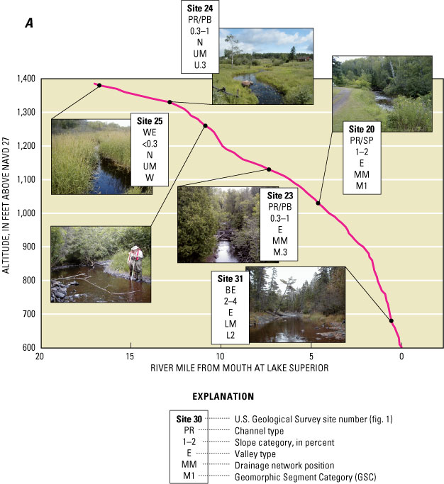
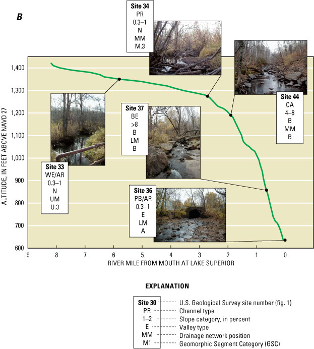
Similar to Lester River, the upper main stem of Miller Creek begins with wetland ditches with gentle slopes (site 33, fig. 11 B ). Site 34 is downstream of an area with extensive shopping development and upstream of the transition from glacial deposits to bedrock at the land surface. The channel type at site 34 is pool-riffle with evidence for recent (within 5 years) channel widening, avulsion (sudden channel movement), and flood scour. The flood plain has about 1.5 ft of post-settlement alluvium. LWD is common and provides some habitat and pools. Downstream, in the steep reach affected by the Duluth-complex gabbro rocks (site 44), the cascade-type channel shows signs of channel expansion in areas with no flood plain or widening in areas with flood plain. There is minimal to no overbank sedimentation through the reach at site 34. This site functions as a transfer zone for upstream sources of sediment and upstream or bank-derived LWD. Site 37 downstream is an example of a bedrock channel with a slope of greater than 8 percent. Similar to Lester River, bedrock channels on Miller Creek show evidence of channel expansion (scoured bedrock along channel margins and trees toppling into the channel) and sediment inputs from landslides and gully development along the tops of valley sides related to storm drains and hiking trails. Downstream of the bedrock-controlled zone, the channel is an artificial plane-bed at site 36.
No intensive sites were on tributaries, but observations and photographs from tributaries or small main stems with rapid assessments indicated that middle and lower tributaries with relatively steep slopes had colluvial, cascade, or bedrock channel types (fig. 12). For example, site 46 on Coffee Creek (considered a tributary to the lower main stem of Miller Creek), was ephemeral and had a mix of colluvial/bedrock channel types (fig. 12 A ). Tributaries to Merritt, Stewart, and Keene Creeks were perennial (figs. 12 B–D ). The Stewart Creek tributary (site 2) had a small colluvial channel that was hidden by vegetation. The Merritt Creek tributary (site 47) had a bedrock channel. The Keene Creek tributary (site 5) had a cascade channel. The amount of scour in the channels was attributed to upstream land cover and effects on runoff and flood peaks. Coffee Creek had an urban watershed; Stewart Creek had a forested watershed. Merritt Creek was forested at the site but had urban development in the upper half of its watershed, and the Keene Creek tributary had a mix of forest and shrubland but local erosion problems from road drainage.
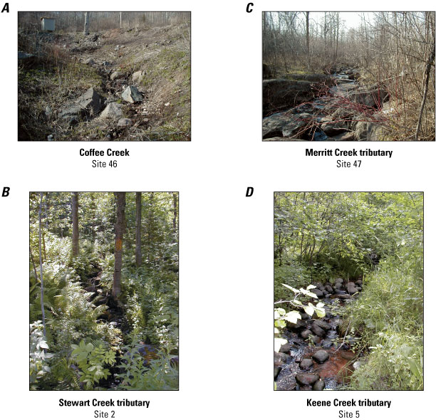
Human activities affect geomorphic processes in Duluth-area streams at multiple spatial scales (tables 5 and 7). Activities include watershed-scale forest clearing for logging, agriculture, or urban development; segment-scale clearing of riparian vegetation for similar purposes, road construction and drainage, and ditching; and reach-scale or local features, such as human-caused channel alterations (straightening, dredging, damming), gravel pits or quarries, road crossings, and hiking trails. Geomorphic conditions in each segment may be affected by upstream changes in the flow regime or sediment inputs, or downstream disturbances such as changes in base level (creation of a reservoir) or straightening (increases slope). Geomorphic processes also may be affected by past activities for which there may be little modern evidence, such as forest clearing, logging, log dams, and log drives following European settlement in the late 1800s.
Each segment has a known or extrapolated set of geomorphic processes that are presently occurring (table 5). For Lake Superior tributaries in Wisconsin, watershed-scale removal of forest vegetation has increased the size of flood peaks and caused increased erosion and sedimentation rates compared to pre-European settlement conditions (Fitzpatrick and others, 1999). Streams in the Duluth area are geologically young and very few are alluvial; thus the textbook concepts of geomorphic stability and potential responses or sensitivity to disturbance that are based on geologically old stream systems in well-developed alluvial valleys may not be applicable (such as development of concave upward profiles described by Hack (1960)).
Example streams that illustrate how geomorphic processes are affected by human activities and disturbance are middle or lower main stems in the Duluth area with entrenched valleys. If their watersheds are completely forested, landslides and bluff erosion would occur episodically where stream meanders intersected valley sides. If a watershed is cleared for urban development, increased runoff and flood peaks would increase stream power, which in turn would increase the erosive potential of the channel, potentially contributing to bank erosion and landslides. Segments with steep slopes and narrow, deep valleys developed in glacial deposits have the most potential for lateral movement and landslides if upstream runoff contributions are increased. Landslide and bluff erosion also can be increased by the creation of gullies from hiking paths, storm drains, and road drainage that concentrate runoff onto erosive or unstable slopes. If a channel is in a bedrock-controlled valley, the likelihood of the occurrence of a landslide is less or minimal during human time scales, but still would be possible in areas that have glacial deposits overlying bedrock. Also, the sensitivity of bedrock channels to disturbance will be less than alluvial channels or channels that flow through glacial deposits.
Another example of geomorphic response to disturbance are middle main stems that flow through glacial deposits but are close to the transition to exposed bedrock, such as at Mission Creek (site 1), Miller Creek (site 34), Chester Creek (site 43), and Lester River (site 23) (figs. 1, 4, and 5). At these sites, Miller and Chester Creeks do not have developed valleys but Mission Creek and Lester River are larger rivers with less resistive bedrock and entrenched valleys. Upstream inputs of water and sediment have changed for all these sites because of land clearing and wetland drainage, most dramatically for Miller Creek because of extensive commercial development in its upper watershed. Downstream, bedrock is a local base-level control, inhibiting incision as a possible geomorphic response to upstream increases in runoff and changes in sediment sources and inputs. The most ubiquitous response in these middle main stems to upstream increases in runoff is channel widening, lateral migration, and avulsion. If the streams have developed valleys, then migration into valley sides causes landslides. Slopes and banks are low enough that overbank sedimentation can result. These streams do not have lateral bedrock controls, and old glacial shorelines and ancient beaches are common in this transition area and deposits from them are easily eroded if they occur along valley sides. Thus, these segments have a high potential for geomorphic change from upstream increases in runoff volumes and flood peaks.
Based on the compilation and interpretation of watershed-, segment-, and reach-scale data, the segments were grouped into 15 geomorphic segment categories (GSCs) with similar geomorphic characteristics and processes (fig. 13 and table 9). The categories are primarily based on slope and drainage-network position and secondarily on geologic setting and valley type. Dominant geomorphic processes are summarized for each category. As stated earlier, the classification is based on reach, segment, and watershed characteristics specific to Duluth-area streams. There may be unknown local disturbance mechanisms that have affected geomorphic processes for some segments that were not field surveyed. This classification is only directly applicable for Duluth-area streams and is useful for showing the importance of linking geomorphic features of a specific reach to drainage-network scale processes. In the Duluth area, streams generally flow perpendicular to their base-level control (Lake Superior or St. Louis River estuary). The boundary between glacial deposits and exposed bedrock, and glacial lake shorelines also run parallel to Lake Superior. Thus, drainage-network position, geologic setting, topography, and valley type are closely related for Duluth-area streams, making the potential sources for and transport of sediment ultimately linked to their position within the drainage network.
[<, less than; >, greater than; LWD, large woody debris. See table 6 for definitions of abbreviations for drainage-network position, geologic setting, valley type, and potential channel type.]
| Segment | Slope (percent) | Drainage network position | Geologic setting | Valley type | Potential channel type | Dominant geomorphic processes in 2003 | Likely pre-European settlement conditions | Potential sensitivity to disturbance | Number of segments |
|---|---|---|---|---|---|---|---|---|---|
| W | <0.3 | UM, UT | SD | N | WE | Incision during floods, aggradation during low flow, runoff source | Channels poorly defined or absent | Low/Moderate | 7 |
| W.3 | 0.3–1 | UM, UT, MT | SD | N | WE | Incision during floods, aggradation during low flow, runoff source | Channels poorly defined | Moderate | 19 |
| U1 | >1–2 | UM | SD | N | PR? | Incision, bank erosion | Not known | High | 4 |
| U2 | >2–4 | UM | SD/BED/SH | C | PB/SP? | Incision, bluff erosion, bank erosion | Not known | Moderate | 7 |
| M.3 | 0.3–1 | MM | SD/SH | N/E | PR | Bank erosion, bluff erosion, lateral migration, bar formation, overbank sedimentation | Meandering pool/riffle channels dominated by gravel with bank erosion limited to outside bends, abundant LWD | Moderate/high | 7 |
| M1 | >1–2 | MM | BED/SH transition | C/E/N | PR/SP | Bank erosion, bluff erosion, lateral migration, bar formation, overbank sedimentation | Meandering pool riffle or step pool channels depending on proximity to bedrock | Moderate/high | 19 |
| M2 | >2–4 | MM | BED/SH | C | SP/PB | Bank erosion, bluff erosion, lateral migration, bar formation | Possibly step-pool channels with gravel, cobble, boulder beds | Moderate/high | 6 |
| B | >4–8+ | MM, LM | BED | C/E | BE/CA | Channel expansion, bluff erosion | Bedrock or step/pool channels, possibly abundant large woody debris | Low | 30 |
| L1 | >1–2 | LM | TP/LA | C/E | PB | Channel expansion, widening | Potentially meandering pool/riffle channels with abundant large woody debris | Low/moderate | 6 |
| L2 | >2–4 | LM | BED/TP transition | C/E | PB/BE | Channel expansion, widening, bank erosion, bar formation | Potentially step/pool channels with abundant large woody debris | Low/moderate | 10 |
| A | 0.3–1 | LM | TP/LA | A/N | PR/AR | Aggradation | Meandering, avulsing sand channels in estuary setting | Low/high | 9 |
| T1 | >1–2 | UT, MT | SD/BED transition | E/C/N | PR? | Incision, widening, bank erosion, gully erosion | Unknown | Moderate/high | 12 |
| T2 | >2–4 | UT, MT | BED/SH | C/E | PB? | Incision, gully erosion, bank erosion | Unknown | Moderate/high | 21 |
| BT | >4–8+ | MT, LT | BED | C | CO/CA | Channel expansion, incision, gully erosion | Poorly defined colluvial channels | Moderate | 19 |
| LT | >2–4 | LT | SD/BED/SH | C | PB/CO/BE | Incision, gully erosion, bank erosion, lateral migration | Poorly defined colluvial channels | Moderate/high | 11 |
Headwater segments with slopes less than 0.3 percent (W) or from 0.3 to 1 percent (W.3) are mainly upper main stems or tributaries to upper main stems in wetlands and lowland areas in the larger watersheds (table 9). The channels are commonly altered by ditching (table 5). Ditching helps speed up runoff to downstream segments with steeper slopes. Many of the channels are bisected by roads and receive runoff from large transportation corridors. Many channels have culvert placement-related problems at road crossings. Channels have water in them and low banks but have little flow between runoff events. Fine-grained, organic-rich material accumulates during low flow within the channels; however, the beds of the channels are on parent material, such as glacial lake clay, which gives the appearance that the fine-grained material is flushed out during runoff events.
Headwater streams tend to respond to increases in runoff by widening rather than incision. There is evidence from the GLO notes that the wetland channels are wider now than they were in the mid-1800s, probably from a combination of ditching, road runoff, and historical upland clearing. For example, at site 25 on Lester River, the channel in 1858 was 3 ft wide compared to 18–22 ft wide in 2003. Occasional LWD from banks provides local habitat and sediment trapping but floods are generally not powerful enough to transport large debris.
Presently (2005), these headwater segments generally have low to moderate sensitivity to disturbance because of gentle slopes, but they have some potential to widen with further increases in runoff. Segments with slopes of 0.3–1 percent are distinguished in the classification from segments with less than 0.3 percent because the potential sensitivity to disturbance may be higher in the channels with greater than 0.3 percent slopes. If runoff is increased through urban development or road drainage, there is a potential that the channels will widen and become greater sources of runoff and fine-grained sediment to downstream segments.
A small number of upper main stems have greater than 1–2 percent or greater than 2–4 percent slopes (U1 and U2 categories, respectively; table 9). These segments are at the upper end of some of the small watersheds that begin at or near the transition zone between glacial deposits and bedrock, such as Chester Creek (greater than 1–2 percent slopes with no valley development), or in bedrock, such as Merritt Creek (greater than 2–4 percent slopes with confined valleys). Potential causes for geomorphic change include urban development or vegetation clearing, road drainage, and channel alterations. The bedrock segments have higher slopes; however, segments in glacial deposits have a greater potential to respond to increases in runoff through incision or widening. Riparian land cover along the segments varies from urban to forest. If forested, segments may be a source for LWD from the banks.
Middle main stems are divided into three groups based on their slope category (M.3, M1, and M2) (table 9). Middle main stems with greater than 1 to 2 percent slopes are the most common in watersheds within the study area.
Middle main stems with gentle slopes (M.3) are in larger watersheds on supraglacial drift upstream of the bedrock outcrops with no valley development or entrenched valleys. Site 23 on Lester River and site 34 on Miller Creek fall into this category. These segments generally have pool-riffle channel types and are large enough to have some alluvium in channel and overbank areas. The main potential cause for disturbance is upstream increases in runoff. Local disturbances, such as channel alteration and road drainage, also may affect geomorphic conditions. Segments function as sediment source zones through bank erosion, widening and possibly increasing bluff erosion where valleys are developed, zones of sediment transfer, and also zones of sediment accumulation in overbank areas and bar formation. Potential for geomorphic conditions to change because of upstream increases in runoff is moderate to high. Riparian areas tend to be forested and are a source for LWD, but LWD has a high potential to be transported downstream during floods or form large log jams at bends.
Middle main stems with greater than 1 to 2 percent slopes (M1) are at the transition zone between bedrock and glacial deposits and have confined or entrenched valleys. These segments mainly function as sediment sources and transfer zones, with local storage of sediment in bars downstream of large eroding banks. Similar to M.3 segments, increased runoff from upstream segments is the main potential cause for disturbance, as well as road and storm drainage. There is more potential for landslides and bank erosion than for M.3 segments because of the steeper slopes and more developed valleys. The M1 segments generally have high sensitivity to disturbance unless developed in bedrock. There is no evidence for historical width changes for M1 segments. Forested riparian areas and upstream segments are sources for LWD. At site 43 on Chester Creek, LWD is providing some bank and bar stabilization and sediment trapping, and, occasionally, some pool scour.
Middle main stems with greater than 2 to 4 percent slopes (M2) have confined valleys and are typically developed in transition zones between glacial deposits, bedrock or glacial shorelines. These segments are generally zones of sediment transfer, with some segments also functioning as sediment sources. Potential disturbances are upstream increases in runoff, and local effects of urbanization and road drainage. Possible geomorphic changes from upstream increases in runoff include widening, bank erosion, landslides, lateral migration, and bar formation. Potential for geomorphic change from disturbances ranges from moderate to high, depending on parent material and valley type. Segments with gabbro bedrock have moderate potential, whereas segments with glacial deposits or sedimentary rocks have high potential.
Bedrock channels with steep slopes (greater than 4 percent slope) (B) are common and are on steep middle to lower main stems with mainly gabbro bedrock (figs. 4 and 13). The valleys contain little or no alluvium, have little or no flood plain, and channel sides and bottom are composed of bedrock. These segments are mainly source and transport zones for water and sediment. Potential disturbances include increased runoff from upstream segments and feeder tributaries, and local landslides and mass wasting from hiking trails, road drainage, and storm sewers. Most of the sediment from the failures is transported downstream. Increases in runoff and flood peaks result in the expansion of the flow area and scour zone but the channel morphology typically remains the same because of the vertical and horizontal bedrock control. Instead, channel erosion may increase through waterfall recession and knickpoint migration (Tinkler and Wohl, 1998). Pools temporarily fill with fine sediment between floods. A comparison of GLO survey notes and 2003 channel surveys from site 44 on Miller Creek indicates that in 2003 the channel possibly was 3–5 ft wider than in 1858. Potential for geomorphic change in these segments is low to moderate because the channel morphology is controlled by bedrock.
Presently, the effect of LWD on channel morphology in these reaches is negligible because most of the wood is not large enough to remain stationary during floods. However, LWD may have had more effect on channel morphology prior to European settlement when the size of the LWD was much larger because trees in the immediate riparian zone and upstream segments were larger. It is possible that some cascade or bedrock channels were step/pool prior to European settlement. Bank-derived LWD may alter channel morphology by providing local and temporary scour or lateral migration caused by temporary steps or log jams. A study of LWD in Washington streams suggested that woody debris affects channel morphology, planform, and flood-plain topography (Abbe and Montgomery, 2002); however, woody debris shorter than half the channel width is unstable and provides only temporary storage of sediment (Montgomery and Buffington, 1993).
Lower main stems with slopes from greater than 1 to 4 percent (L1 and L2) are in Lester River and Mission Creeks and other watersheds in the southwestern part of the study area (fig. 13). These segments generally have entrenched or confined valleys developed in a range of geologic materials (table 5). Many of the channels have human-caused channel alterations and have been straightened or have extensive bank stabilization and grade control. These channels function as zones of sediment transport. Causes for disturbance include increased runoff and sediment from upstream segments, road drainage, concentrated drainage and landslides from storm sewers and hiking trails. Segments that are bedrock controlled have flow expansion from increased runoff. Widening and lateral migration may occur in alluvial channels that have not been artificially stabilized. A comparison of channel widths at site 31 on Lester River for 1858 and 2003 indicates that the channel has widened by 5 ft or more. Potential for geomorphic change generally is low to moderate depending on parent material and slope.
Aggradational lower main stems (A) are uncommon in the study area (fig. 13). These segments are on till or lake plain and drain to the St. Louis River estuary (fig. 1). Channels typically are artificially constructed plane-bed channels, such as those at site 38 on Mission Creek. The lower main stem of Sargent Creek potentially is the least affected by human-caused channel alterations. The gentle slopes are conducive to sediment accumulation in overbank areas and in channels. Potential causes for disturbance to these channels include increases in runoff and sediment from upstream areas and concentrated drainage from roads. These streams also are naturally affected by slowly rising water levels in Lake Superior due to regional differences in crustal rebound after glacial ice melted from the region about 10,000 years ago (Larsen, 1994). Potential sensitivity to disturbance ranges from low to high, depending on how channel alteration and hardening has occurred. The source and function of LWD in these segments is unknown. At site 38 on Mission Creek (fig. 1), LWD was rare, with some trees falling in from the banks.
As mentioned previously, less time, effort, and field checking was spent on tributaries, especially those that are ephemeral. The majority of the approximately 70 tributary segments are ephemeral and 4 of the 15 GSCs are based on tributaries (T1, T2, BT, and LT; table 9). The divisions for the four categories mainly reflect the potential for the tributaries to incise or form gullies. All four categories are considered source areas for sediment and runoff to main stems. Major causes for disturbances are land clearing, urbanization, concentrated drainage from roads or storm sewers, and gravel pits and quarries. Forested riparian zones provide LWD sources; LWD function likely varies depending on slope.
Tributaries with greater than 1–2 percent slopes (T1) generally flow on glacial deposits and tributaries with greater than 2–4 percent slopes (T2) flow on bedrock or glacial lake shoreline deposits. Valley types for T1 segments include undeveloped, confined, and entrenched, whereas valleys for T2 segments are confined or entrenched. Many of the T1 and T2 segments are in the Mission Creek watershed, with T2 segments on the eastern side of the watershed because there is more relief coming off of the Duluth gabbro complex and T1 segments on the western side because there is less relief related to the lake plain/till plain and sedimentary bedrock. Both T1 and T2 segments have moderate to high potential for incision, bank erosion, and landslides. Steeper segments have more potential for erosion unless they are bedrock controlled. Steep segments that intersect glacial lake shoreline deposits have the highest potential for erosion.
Tributaries with confined bedrock valleys (BT) have steep slopes and are also sources of runoff and some sediment to bedrock main stems. Many tributaries are in urban areas. Even though slopes are steep, potential sensitivity to disturbance is moderate because incision and widening are limited by the presence of bedrock in channel margins.
Tributaries to lower main stems (mainly Amity and Mission Creeks) with 2–4 percent slopes are colluvial channels in confined valleys (LT) and are sources for runoff and sediment. These segments have moderate to high potential to incise, widen, and produce gullies and landslides because of their proximity to main stems with entrenched valleys.
Streams in 20 watersheds in the Duluth, Minn. area were studied by the USGS in cooperation with the city of Duluth in 2003–04 to identify channel geomorphic characteristics and processes, identify potential causes for geomorphic changes related to disturbance, and develop a classification reflective of characteristics, processes, and potential for geomorphic change. These goals were accomplished by collecting watershed-, segment-, and reach-scale geomorphic data from digital maps, historical maps and notes, aerial photographs, and rapid assessments and intensive surveys. Understanding the geomorphic conditions and processes of these streams is important because they relate to overall water and aquatic-resource quality and adjacent plant and animal habitat.
Streams in the Duluth area have been affected by a variety of historical land uses. Main causes of historical and present geomorphic disturbance include logging, agriculture, ongoing urban development, human-caused channel alterations, road and storm sewer drainage, ditching, hiking trails, and gravel pits or quarries. Geomorphic responses to these disturbances are dependent on a combination of drainage-network position, slope, and geologic setting. Almost all of the channel segments have undergone some geomorphic changes from past human-related disturbances.
Segments were classified into 15 unique geomorphic-segment categories primarily based on differences in drainage-network position and slope, and, secondarily, based on geologic setting, valley type, and dominant geomorphic processes. The categories accounted for major differences in geology and valley types because stream networks generally are perpendicular to the Lake Superior shoreline, and a major contact between glacial deposits and exposed bedrock parallels the Lake Superior shoreline. The three major bedrock types in the Duluth area have a range in erosion resistance; the least resistant are the Animikie Group sedimentary rocks in the Mission Creek watershed, the most resistant are the Duluth Complex gabbro intrusions in the center of the city; and the Keweenawan volcanic rocks in the Lester and Amity River watersheds are moderately resistive.
Because of insufficient slope or bedrock control, most of the drainage networks in the Duluth area have low to moderate potential for channel change from future disturbance. Some channels cannot incise further because bedrock acts as grade control, but channels can be sediment sources from widening, bank erosion, and landslides (in confined or entrenched valleys). Most of the headwaters segments with gentle slopes at altitudes about 1,200 ft above NAVD27 have been ditched or channelized. Combined with urban development and concentrated road drainage, these segments are primary sources for runoff and secondary sources of sediment to downstream segments. Middle main-stem segments are at altitudes from about 1,200 to 1,000 ft and have moderate slopes in confined or entrenched valleys that are in the contact zone between glacial deposits, bedrock, and glacial-lake shorelines. These segments have a high potential for channel change and are primary sediment sources because they have confined or entrenched valleys with sandy glacial-lakeshore deposits.
Below about 1,000 ft, main-stem segments and tributaries generally are affected by bedrock type and structure and have steep slopes and confined or entrenched valleys. Increases in flood peaks usually do not cause incision or widening in bedrock-controlled valleys; instead, the flow and scour area is expanded into riparian zones along the channel boundaries. Feeder tributaries to these main stems have steep, confined valleys and may be sources for runoff and sediment from urban areas or road and storm sewer drainage. Tributaries with glacial deposits overlying colluvium have a high potential for incision, widening, and landslides and mass wasting from valley sides. Aggradational or gentle-sloped lower main stems are in flat areas of till plains or fill between the bedrock bluffs and Lake Superior or the St. Louis River. These channels are mainly artificially constructed or stabilized.
The segment-scale classification developed for this study can be used as a screening tool to distinguish channels that may require extra attention and care in preventing landslides and bank erosion. The classification is an initial step toward a better understanding of the spatial distribution of channels with similar geomorphic processes. The classification can be refined as more reach-scale geomorphic data are collected, especially for tributary segments. The classification could be improved and verified through quantitative geomorphic measurements at additional intensive survey sites and further monitoring at established intensive survey sites.
Todd Bohle (Seattle Public Utilities–Washington) assisted with initial stream characterization and review of historical aerial photos. Kyle Deming (city of Duluth) helped to guide study goals and approach and provided digital maps of Duluth urban features. Meghan Hannon (USGS Minnesota Water Science Center) assisted with field surveys and historical aerial photography interpretation. Christopher Sanocki, Andrea Bergman, and Paul Oduro (USGS Minnesota Water Science Center) provided digital maps of drainage boundaries, bedrock, glacial deposits, land cover, and population density. Jacqueline Hamilton (USGS Minnesota Water Science Center) obtained Government Land Office Survey notes. Meredith Cornett, Brian Schreurs, Thomas Duffus, and Daryl Peterson, all of The Nature Conservancy (Minnesota), are thanked for assistance with digital maps, input on study design, and technical insights. Todd Bohle, Daryl Peterson, David Montgomery (University of Washington), and Timothy Diehl (USGS Tennessee Water Science Center) provided technical reviews. Editorial review was completed by Angel Martin (USGS Illinois Water Science Center). Michelle Greenwood and Jennifer Bruce (USGS Wisconsin Water Science Center) created publication-quality graphics and did the layout design.
Abbe, T.B., and Montgomery, D.R., 2002, Patterns and processes of wood debris accumulation in the Queets River Basin, Washington: Geomorphology, v. 51, p. 81–107.
Bohle, Todd, 2002, Stream channel assessment of the Caribou, Manitou, and East Branch of the Baptism watersheds: Unpublished report to The Nature Conservancy, January 4, 2002, 34 p.
Camp Dresser and McKee, Inc., 2000, Technical memorandum, assessment of watersheds, City of Duluth: St. Paul, Minn., Camp Dresser and McKee Inc., 35 p.
Eichenlaub, V. L., 1979, Weather and climate of the Great Lakes region: Notre Dame, University of Notre Dame Press, 335 p.
Fitzpatrick, F.A., Waite, I.R., D'Arconte, P.J., Meador, M.R., Maupin, M.A., and Gurtz, M.E., 1998, Revised methods for characterizing stream habitat in the National Water-Quality Assessment Program: U.S. Geological Survey Water-Resources Investigations Report 98–4052, 67 p.
Fitzpatrick, F. A., Knox, J. C., and Whitman, H. E., 1999, Effects of historical land-cover changes on flooding and sedimentation, North Fish Creek, Wisconsin: U.S. Geological Survey Water-Resources Investigations Report 99–4083, 12 p.
Gibson, R.J., Haedrich, R.L., and Wernerheim, C.M., 2005, Loss of fish habitat as a consequence of inappropriately constructed stream crossings: Fisheries, v. 30, no. 1, p. 10–17.
Goebel, J.E., Mickelson, D.M., Farrand, W.R., Clayton, L., Knox, J.C., Cahow, A., Hobbs, H.C., and Walton, M.S., Jr., 1983, Quaternary geologic map of the Minneapolis 4o by 6o quadrangle, United States: U.S. Geological Survey Miscellaneous Investigations Series, Map 1–1420 (NL–15), scale 1:1,000,000.
Hack, J.T., 1960, Interpretation of erosional topography in humid temperate regions: American Journal of Science, v. 5, p. 258-A, p. 80–97.
Hack, J.T., 1965, Postglacial drainage evolution and stream geometry in the Ontonagon area, Michigan: U.S. Geological Survey Professional Paper 504–B, 40 p.
Harrelson, C.C., Rawlins, C.L., and Potyondy, J.P., 1994, Stream channel reference sites: an illustrated guide to field technique: U.S. Department of Agriculture, Forest Service, General Technical Report RM–245, 31 p.
Hobbs, Howard, 2004, Late Wisconsinan Superior-Lobe deposits in the Superior Basin northeast of Duluth: in Severson, M.J., and Heinz, Julie, Proceedings of the Institute on Lake Superior Geology, 50th Annual Meeting, Field Trip Guidebook, v. 50, p. 86–98.
Knighton, D., 1998, Fluvial forms and processes: New York, Oxford University Press, Inc., 383 p.
Larsen, C.E., 1994, Beach ridges as monitors of isostatic uplift in the upper Great Lakes: Journal of Great Lakes Research, v. 20, n. 1, p. 108–134.
Leverett, Frank, 1929, Moraines and shore lines of the Lake Superior Region: U.S. Geological Survey Professional Paper 154–A, 72 p.
Milfred, C.J., Olson, G.W., and Hole, F.D., 1967, Soil resources and forest ecology of Menominee County, Wisconsin: Madison, Wis., University of Wisconsin, Geological and Natural History Survey, Soil Survey Division, Bulletin 85, Soil Series No. 60: 203 p., 3 pls.
Miller, J. D., Green, J. C., Severson, M. J., Chandler, V. W., and Peterson, D. M., 2002, Geologic map of the Duluth Complex and related rocks, northeastern Minnesota: Minnesota Geological Survey Miscellaneous Map Series M–119, scale 1:200,000.
Minnesota Department of Natural Resources, Division of Forestry, 2002, GAP Land Cover, Tiled Raster: 30-meter resolution.
Minnesota Department of Transportation, 2001, Minnesota Department of Transportation Base Map 2001, Runway: 1:24,000 digital data.
Montgomery, D.R., and Buffington, J.M., 1993, Channel classification, prediction of channel response, and assessment of channel condition: Washington Department of Natural Resources Report TFW-SH10-93-002, Olympia, Wash., variously paginated.
Montgomery, D.R., and Buffington, J.M., 1997, Channel-reach morphology in mountain drainage basins: Bulletin of the Geological Society of America, v. 109, p. 596–611.
Montgomery, D.R., and Buffington, J.M., 1998, Channel processes, classification, and response, in Naiman, R.J., and Bilby, R.E., River ecology and management: New York, Springer-Verlag, Inc., p. 13–42.
Munsell Color, 1975, Munsell soil color charts: Baltimore, Munsell Color Division of Kollmorgen Corp., variously paginated.
Schumm, S.A., 1977, The fluvial system: New York, John Wiley and Sons, Inc., 338 p.
Schwartz, G.M., 1949, The geology of the Duluth metropolitan area: Minneapolis, Minn., University of Minnesota, Minnesota Geological Survey Bulletin 33, 136 p.
Soil Survey Staff, 1951, Soil survey manual: U.S. Department of Agriculture, Agricultural Handbook 18, 503 p.
Thorne, C.R., 1998, Stream reconnaissance handbook: Chichester, West Sussex, England, John Wiley and Sons, 133 p.
Tinkler, K.J., and Wohl, E.E., 1998, A primer on bedrock channels, in Tinkler, K.J., and Wohl, E.E., eds., Rivers over rock: fluvial processes in bedrock channels: Washington D.C., American Geophysical Union, p. 1–18.
University on Minnesota-Duluth Geology Department, Minnesota Geological Survey, and Minnesota Department of Natural Resources, 1997, Geomorphology of Minnesota, St. Paul, Minn., Minnesota Geological Survey: scale 1:100,000 digital data.
U.S. Census Bureau, 2000, Census data for 2000: U.S. Census Bureau data, accessed February 10, 2006 at http://factfinder.census.gov
Van Riper, D., unpublished data, St. Louis County Census Tracts for 1940, 1960 and 1980: University of Minnesota Department of Geography, digital data.
Wolman, M.G., 1954, A method of sampling coarse river-bed material: Transactions of the American Geophysical Union, v. 35, no. 6, p. 951–956.
Young, H.L., and Skinner, E.L., 1974, Water resources of Wisconsin-Lake Superior Basin: U.S. Geological Survey Hydrologic Investigations Atlas HA–524, 3 sheets.
Document Accessibility: Adobe Systems Incorporated has information about PDFs and the visually impaired. This information provides tools to help make PDF files accessible. These tools convert Adobe PDF documents into HTML or ASCII text, which then can be read by a number of common screen-reading programs that synthesize text as audible speech. In addition, an accessible version of Adobe Reader, which contains support for screen readers, is available. These tools and the accessible reader may be obtained free from Adobe at Adobe Access.
| AccessibilityFOIAPrivacyPolicies and Notices | |
 |
|