Lava-Cooling Operations During the 1973 Eruption of Eldfell Volcano,
Heimaey, Vestmannaeyjar, Iceland
U.S. Geological Survey Open-File Report 97-724
Lava Cooling on Heimaey--Methods and Procedures3:
|
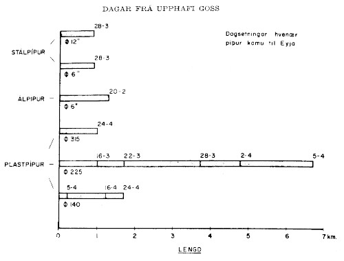
Pipes and Distribution SystemWhen the cooling first started, 6-inch [15-cm] aluminum pipes, that were easily connected, were used along the lava margin. Nozzles were made for some of the pipes, and fire hoses were connected to them. When the dredge Sandy arrived in the beginning of March, pipes were laid onto the red-hot lava, and water was pumped out of the pipe ends. In addition, water was allowed to drip at the joints. These pipes were very heavy and inflexible and tended to break as the lava moved. After the middle of March, plastic pipes from Reykjalundur[-Vinnuheimill SÍBS of Reykjavík] started to arrive. Those pipes were 225 mm [9 in] in diameter and were at first used from Sandey up along the northeast margin of the lava that flowed on 23 March. A successful attempt was made to pump 200 l s-1 of seawater there for about 24 hours, before the lava advanced again on 25 March. The area that had been cooled remained firm. It is quite evident from an aerial photograph how the lava flow curved around it. Figure 12 is a summary of the types and quantities of pipe used in the cooling that [eventually] totaled more than 12 km. A little more than three-quarters of the pipes were the plastic pipes from Reykjalundur[-Vinnuheimill SÍBS]. They served extremely well, and it is doubtful what the outcome would have been if they had not been available. The plastic pipes (140, 225, and 315 mm) [6 in, 9 in, and 12 in] arrived in 15-m-long sections that were welded together into 100-200-m-long sections at the Básaskers Wharf. These [lengthy] sections were then hauled to their respective places and welded together on the spot or joined by connectors. It took from one to two days to lay a 1-km-long pipeline, because only one welding machine was available in Iceland. In the beginning, it was extremely difficult to transport the plastic pipes up onto the lava, because the lava was moving 1-2 meters every hour, and there was also the danger of the plastic melting. However, because of the flexibility of the plastic pipes, this was successful beyond all hopes, because the water running through them cooled them enough to withstand the heat.
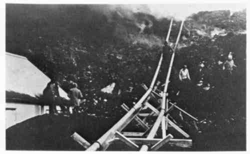
Wooden supports (fig. 13) were placed under the pipes, but where it was hottest the wood burned without exception. Aluminum and asbestos supports were then used; the [fact that] the aluminum supports melted clearly shows how resistant the plastic pipes were [to the high temperatures].
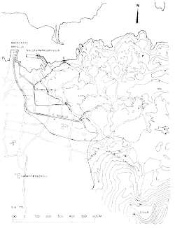
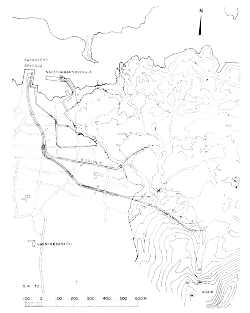
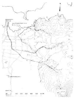
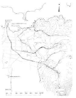
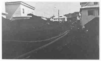
Figure 14A, fig. 14B, fig. 14C and fig. 14D show the positions of the pipelines at four different times. [Figure 15, see below, shows two sets of pipelines laid on top of a tephra-filled street.] On 5 April, after all of the pumps had been installed, they were mostly concentrated on cooling the lava edge on the northern and western sides. On 15 April, the pipelines extended further onto the lava field near Sólhlíð and two new
pipelines, each about 1,600 m long, lay on the lava field north of the crater, 90 meters above sea
level. On 30 April, pipelines had been laid further onto the lava field, especially around the
center of the area that was being cooled. On 30 May, the pipelines reached their final planned
distribution. By that time, the objective of cooling the lava flows west of an imaginary line
extending [north] from the [Eldfell] crater to the [west] side of Yztiklettur was achieved. The
pipelines were not significantly moved from then on, from 19 June until 10 July, when cooling
was gradually decreased.
It should be mentioned that Prófessor Þorbjörn Sigurgeirsson's advice was [closely] followed
in deciding which areas to cool. The professor also followed the movement of the lava and
suggested the areas of [greatest] danger. | ||||||||||||||||||||||||||
| |||||||||||||
