
Digital Mapping Techniques '00 -- Workshop Proceedings
U.S. Geological Survey Open-File Report 00-325
Geomatter II : A Progress Report
By Eric Boisvert1, Vincent Desjardins2, Boyan Brodaric3, Brian Berdusco4, Bruce Johnson5, and Kathleen Lauzière1
1Geological Survey of Canada
Quebec Geoscience Center
880 Ch. Ste-Foy
Québec, Québec, Canada, G1V 4C7
Telephone: (418) 654-3705
Fax: (418) 654-2615
e-mail: eboisver@nrcan.gc.ca, klauzier@nrcan.gc.ca
|
2Recrusoft
390, St-Valier Est, bureau 401
Québec, Canada G1K 3P6
e-mail: vdesjardins@recruitsoft.com
|
3Department of Geography,The Pennsylvania State University
302 Walker Building
State College, PA , USA 16802-5011
e-mail: bmb184@psu.edu
|
4Ontario Geological Survey
Willet Green Miller Centre, Level B7
933 Ramsey Lake Rd.
Sudbury, ON, Canada P3E 6B5
e-mail: brian.berdusco@ndm.gov.on.ca
|
5United States Geological Survey
954 National Center
Reston, VA, USA. 20192
e-mail: bjohnson@usgs.gov
|
INTRODUCTION
GeomatterII (Geologic Map Attributer - or Geoscience Map Attributer) is a data entry and editing tool to enable the management of NADM (North American Data Model) structured databases (Johnson and others, 1998). The NADM is the result of a joint effort between American and Canadian geoscience representatives from federal and state/provincial agencies. The steering committee of the group produced a series of logical models, the last being called "version 4.3" to structure map related geological information. The complexity of the model was seen as a problem for most geoscientists who have limited knowledge of database design and implementation.
Geomatter II has been developed to shield the casual user from database implementation details while still allowing expert users to extend and modify some parts of the database structure. It provides a graphical user interface where the map and associated information are displayed in a tightly-integrated application. The interface is built around a "selection state" engine, where every piece of information is highlighted/displayed according to the current selection. This selection can be triggered from various data controls within the interface (maps, datasheets, tree views, etc.) and all other components of the application will respond accordingly.
The first version of Geomatter (then called IGMDM, Interface for the Geological Map Data Model) was presented at the last DMT (DMT '99, Madison, WI) and a full description of the application is available in Brodaric and others (1999a). It was then a slightly clunky demo application, crippled with bugs and built to address a very specific data model version that was a little different from the, then current, v. 4.2 model. While this software could hardly be used in any serious application, it showed how an application could hide database complexity behind a friendly interface.
The United State Geological Survey (USGS), Ontario Geological Survey (OGS) and Geological Survey of Canada (GSC) funded another round of development to improve this prototype application to a version that can be used in a real project. Several technological and philosophical problems had to be addressed to create this application. For a discussion on the rationale behind Geomatter, the reader is referred to Brodaric and others (1999a). The logic of the application has been kept identical and effort has been concentrated on improvement of the prototype.
Software and Hardware
Geomatter is a stand-alone application that runs on Win9x/NT computers; it has not yet been tested on the Windows 2000 or Windows "me" (millennium edition) operating systems. The application is build around ESRI MapObjects 1.2 ActiveX and ODBC API. The code was written in Delphi 5 (Inprise/Borland). A blank MS Access 97 database following either v.4.3 structure or v.5.2 (Cordlink) structure is available with the application. The Cordlink data (Brodaric and others, 1999b) is an adaptation of the NADM to support a web-enabled virtual library. Geomatter uses ESRI shape files for its geospatial archives.
Geomatter follows in the footsteps of key NADM applications such as Curly (Raines and Hastings, 1998) and LegendMaker (Sawatzky and Raines, 1998). The application is available to NADM participants but cannot be widely distributed due to licensing issues of one of the internal component (MapObjects).
Hiding Database Complexity
The goal of the application is to hide the database complexity behind a user interface that presents the user a set of known concepts, such as a map, polygons, lines, points, legend items, etc. Geomatter is a "conceptual" representation of the database model (Brodaric and others, 1999a) , as understood by the data model designers. The application then communicates using a logical representation (using SQL) of the data model to interact with a physical implementation of the database (in MS Access).
DEVELOPMENTS AND IMPROVEMENTS
While this document is not intended to be a highly technical description of Geomatter, following are several brief highlights of GMII development and improvements. Instead of trying to patch up code in the original version, the application was rewritten, using what had been learned from the previous version. Several problems were due to the initial design of the application, while new challenges have been added by the new sets of specifications required by the stakeholders. The general layout of the application has not changed dramatically but the inner design is built around a more expandable "programming style" - or as it is called in the programmer circles; "design pattern". The appendix shows a series of "snapshots" to avoid cluttering the text with too many figures.
Abstraction of the Application
The most dramatic change in the application is the design pattern. The user interface is now shielded from the database structure, up to a certain point, by a specific software component (labeled API) in figure 4a and 4b. This means that minor changes in the data model (and, therefore, in the database) will not require changes in the application. These changes can be handled by changing the SQL commands that are physically located in the database in a special table.
The application is also somewhat shielded from parts of the interface since they behave as independent pieces of software. Additional interface segments can be added without interfering with other parts of the application. This design style was adopted in the earlier version, but the current version implements a more formal system.
The application is also built assuming a need for future changes. This flexibility allows the addition of new COA (Compound Object Archive) and SOA (Singular Objects Archive) related tables at will (see Johnson et al, 1998 for full description of COA and SOA concepts). Special data tables are created within the database to store application metadata, such as the list of tables that are to be filled by the user, what pick list to display, etc. This allows expansion of the data model to suit particular needs. To gain this flexibility, Geomatter must create forms on the fly from database content (figure 1), requiring the inclusion of a series of "System tables" within the database to store information needed by the application (this will be discussed in "User defined database structure").
Script-Based Customization
When a new database is created, Geomatter connects to an empty data structure, which is provided with the application. When the connection is established, Geomatter performs a series of tests to identify a) what version of the database is being used, and b) if all system tables are available. System tables are specific tables that hold information about the variables parts of the database (i.e. COA related tables , such as Rock_Unit, Metamorphic_Unit, and SOA tables such as SOANames, SOAFossil, etc.). These tables also hold information about "Aliases". An Alias is human readable text that is displayed in a field instead of an id. Most foreign keys in the database are numerical ids that refer to information stored in other table. When a table is displayed to the user, this numerical key must be replaced by text fetched from the related table.
Hierarchical Legend Component
The legend component reflects the COA organization it is linked to. Legend items are displayed as a hierarchical tree where the COA hierarchy determines the locations of the legend items. Since a single legend item is related to a single COA, the tree structure of the legend simply reflects the COA's structure. It is not possible to alter the hierarchical organization of legend items (except when the legend is not associated with a COA). Altering the COA structure will be automatically reflected in the legend panel. It is also possible to "collapse" the legend tree to generalize the legend content. When a legend item is collapsed, the related spatial objects (on the map display) automatically use the parent symbolization (figure 2).
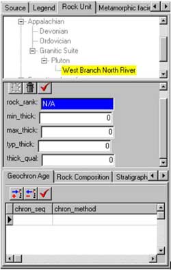
Figure 1. A typical data panel showing the COA navigator (top), a COA related table (middle) and all the related attribute tables (bottom).
|
|
|
|
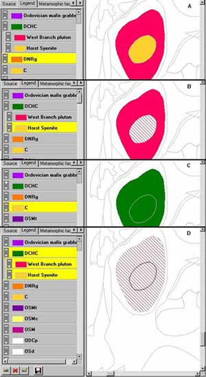
Figure 2. A) Legend in initial state, note hierarchical structure. B) Sub-item selected, selection is highlighted in yellow (appears in a different shade of grey on the figure) in the legend and diagonal lines on the map. C) Legend sub-items collapsed into their parent, note map generalization. D) Selection of the parent while children are visible, children are automatically selected.
|
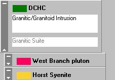
Figure 3. Legend items in different states. The parent (topmost) is in expanded form while the remaining are in contracted form.
|
Legend items can be displayed in two forms, expanded and contracted (figure 3). The expanded version shows all attributes of the legend (the classification_object). This was implemented to allow more than 3 or 4 items to be displayed simultaneously in the restricted area of a computer screen.
Customizable Pick List
Several fields in the database must be filled with specific keywords to impose consistency. Keywords are located at different places within the database. They can either be references to other attribute tables (e.g. Source) or can be keyword tables that are used for this purpose only (e.g. Rock_Unit_Rank). Since the application can accommodate user defined tables, a mechanism to customize pick lists has also been implemented. This module has been the most complex part of the application to create because of the large number of variables to take into account. The pick list mechanism had to be able to handle both tree and linear structures, allow (or deny) users to add new items, thus leading to the ability of the pick list manager to launch other pick lists to populate themselves. The mechanism is built around the SYSDIX (System Dictionary) table that keeps information about every potential picklist. New picklists can be created by adding records to this table. Appendix figures 6,7 and 8 show pick lists.
Legend Builder
In many cases, the map to be attributed exists as a digital file that contains the necessary information to create a classification (legend items). It would be a major burden to re-attribute every line or polygon manually when this information was already available in the GIS file. A small tool has been included to automatically read information from the GIS file and create legend items. New legend items are not linked to any COA; this is left to the operator.
Abstracted Database Access
This topic can become very technical, and we will simply state that a lot of effort has been made to accommodate changes to the data. Two mechanisms have been used: 1- Usage of a SQL library, and 2- Modular design. Chances are that the first approach will be abandoned because its implementation and maintenance is too complicated. Geomatter I was restricted to a very specific implementation of the database and any changes required a rewrite of the application. Adding new tables to the data model to expand its data content to other concepts was simply not handled by the first version of the application (see next section). Figure 4 compares versions 1 and 2.

|
Figure 4. a) The logical (SQL) design of the application was "hard coded" into Geomatter I while it has been moved into the physical portion (i.e. in the database) for Geomatter II. b) The application now calls a specialized module (API) using a unique (conceptual) syntaxes, that is in turn converted into logical statements (SQL command), stored in the database with the data.
|
Figure 4 shows that all the SQL commands required to communicate with the database have been moved into the physical database (instead of being located within the application). This allows changes to be made to the SQL commands to adapt to slight changes of the data model. But this approach has its share of problems because this list of SQL commands is specific to each database implementation. Every change or correction to the application involving this list of SQL command brings a tedious process of updating both the application and the SQL commands on every version already installed. This is where backward compatibility problems start occurring. Any change of the SQL commands proves to be a very delicate task. A very deep understanding of how the data model and the application work was needed to do this. This design was chosen to allow users to alter the application's behavior and to adapt it to other versions of NADM. But the complexity of this task prevents anyone from trying this, except for the very adventurous.
The second method of abstraction is the use of a component approach for the design of the application. The application deals with a set of components written for a specific database structure. This is how Geomatter can accommodate version 5.2 (an adaptation of NADM for Virtual Libraries such as Cordlink). The application communicates with a "data-panel-that-handles-data-of-type-x" instead of dealing directly with data of type x (figure 5). The application can then access various versions of the model by loading the appropriate modules.
Figure 5. Geomatter I was a monolithic application where new controls required a lot of reprogramming. The new design allows new components to be added with less work.
|
User-Defined Database Structure
Another challenge of this version was to allow the user to add their own data tables and modify fields of existing data tables. For those familiar with the database structure, variable data tables are the COA tables (those attached to a COA concept, such as Rock_Unit and related tables such as lith_form) and the attributes attached to spatial objects (SOA tables). The application has to accommodate a varying number of tables having various field lists, all of them potentially linked to various picklists and other attribute tables. This is basically what the data panel shows on figure 1 (and Appendix, figure 4). The top section is the COA tree (replicated on every data panel, it can be used to navigate or to edit by double clicking on it), the central section is the COA related table (e.g. Rock_unit) and the bottom part are attribute tables related to the central section. These panels are generated dynamically from the database content. The list of tables that can appear in the bottom panel is also located within the database and , thus, is customizable. The pick lists described in an earlier section allow access keyword lists on any of the fields.
FUTURE DEVELOPMENTS
The goal of Geomatter is to allow users to enter data into NADM compliant databases and support a certain level of browsing. The current version of Geomatter is aimed at manual map attribution; however, several modules could be very useful for converting maps into NADM. For instance, it is not possible from the current interface to import a large number of SOA entries into an existing table (but one can easily add the whole table as a new entity). Export is also lacking, partially because no formal exchange format is yet available. In projects where we use Geomatter (such as Hydrolink, which is essentially a version of Cordlink for hydrogeology), some browsing tasks are delegated to a web interface. The application does not support multi-user access to the same database very well (actually, it relies on pure chance when connected to Access because it has an "optimistic" approach to table locking). So, areas of improvement in the short term should concentrate on import/export and multi-user capacities.
CONCLUSION
This current version, unlike its predecessor, is a workable application that is already in use in two internal projects at GSC-Québec. The usage of the tool so far is oriented towards web publication (where it is used in conjunction with other tools such as Cordlink ColdFusion+Mapguide engine) of hydrogeological information (Hydrolink) and geological information (GASL, or Geological Atlas of St-Lawrence valley). The goal of the tool is still single user codification of simple maps but the current design of the application allows others to build on top of current development and add more functionality rather easily (the Legend builder took a few hours to implement).
Geomatter II reached one of its goals when it was at its alpha stage during the winter of 1999-2000; it gave casual users access to NADM databases so they could experiment with them. This is exactly what happened within GSC-Québec and the rest of the GSC. Momentum was generated for use and adoption of the NADM when the application was demonstrated and people could actualy see what all those boxes on the NADM chart really meant.
ACKNOWLEDGEMENT
Special thanks to the USGS, the OGS and the GSC for funding. Gratitude is expressed to Andrée Bolduc (GSC-Québec) and Dave Soller (USGS) for their review of the manuscript.
REFERENCES
Brodaric, Boyan, Boisvert, Eric, and Lauzière, Kathleen, 1999a, Geomatter: A Map-Oriented Software Tool for Attributing Geologic Map Information According to the Proposed U.S. National Digital Geologic Map Data Model, in D.R. Soller, ed., Digital Mapping Techniques '99 -- Workshop Proceedings: U.S. Geological Survey Open-File Report 99-386, p. 101-106, https://pubs.usgs.gov/openfile/of99-386/brodaric2.html.
Brodaric, Boyan, Journeay, Murray, Talwar, Sonia, and Boisvert, Eric, 1999b, Cordlink Digital Library. Geological Map Data Model, Version 5.2, June 18, 1999, http://132.156.108.208/Cordlink1/.
Johnson, B.R., Brodaric, Boyan, Raines, G.L., Hastings, J.T., and Wahl, Ron, 1999, Digital Geological Map Data Model 4.3, http://geology.usgs.gov/dm/model/Model43a.pdf.
Raines, G.L., and Hastings, J., 1998, Curly and Curly survival guide, http://geology.usgs.gov/dm/tools/Curly/.
Sawatsky, D.L., Raines, G.L., LegendMaker and LegendMaker Guide, http://geology.usgs.gov/dm/tools/LegendMaker/.
APPENDIX
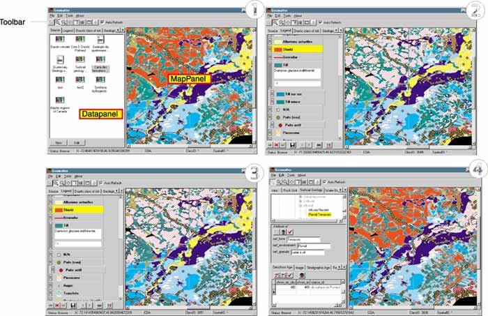
View 1. View of the interface upon connection. One source item has been selected and the map is shown on the right. Data panel on the left displays data entry controls (selected using tabs on the top). Content and number of panels is defined by the database content.
View 2. Data panel showing the legend control (here, surficial geology in French). Canadian shield is selected in the legend control, and the corresponding polygons are shown in dashed pattern. The legend shows a hierarchical structure derived from the COA structure. The till legend item has two siblings (till and rock and till veneer) and is shown in expanded form, whereas others are in contracted form.
View 3. The same maps as in View 2, but till tree is closed. Note that the map is now generalized to this level.
View 4. Data panel shows the data entry panel. The central panel is generated from the structure of the underlying table automatically. The detail table at the bottom is determined from information located in the database, and hence is totally customizable. Light color font shows 'aliasing' in action where a numerical id is replaced by text (also customizable).
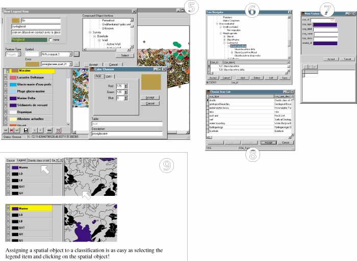
View 5. Creating and editing legend items is done visually. The COA tree is listed on the right. Double-clicking on the COA tree opens a COA editor window (view 6).
View 6. COA editor, position in the tree can be altered at will.
View 7. Creating a new entry. This dialog is generated automatically from information in the database. Dark fields announce that these fields will trigger another picklist.
View 8. A linear picklist (as opposed to a tree picklist, shown in view 6). Picklists can be associated with any field in the database.
View 9. Assigning a spatial object to a classification (legend item).
U.S.Department of the Interior, U.S. Geological Survey
<https://pubs.usgs.gov/openfile/of00-325/boisvert.html>
Maintained by Dave Soller
Last updated 11.01.00