Open-File Report 01-425
The internal structure of sand bars on the Colorado River, Grand Canyon, as determined by ground-penetrating radarU.S. Geological Survey Open-File Report 01-4252001Walter Barnhardt, Robert Kayen, David Rubin, and Diane MinasianContents:AbstractIntroduction Methods Types of Alluvial Deposits Thickness of Sand Deposits Description of GPR Units A Possible 1983 Flood Deposit Characterization of Alluvial Sediment with GPR Acknowledgments References
AbstractHigh-resolution, subsurface imagery from ground-penetrating radar (GPR) has revealed the internal structure of sand bars at seven sites on the Colorado River, Grand Canyon. Based on reconnaissance-level surveys, we recognized three stratigraphic units and several intervening unconformities. Unit A, which exhibits hyperbolic reflections and always occurs at the base of the section, is interpreted as bedrock and/or talus. Unit B is a commonly observed sand deposit that overlies unit A and is characterized by reflections that gently dip down toward the river axis. Unit C is a sand deposit up to 2 m thick that always occurs at the top of the section and may represent a flood deposit from 1983. This study demonstrates the utility of GPR for non-destructive investigation of sand-bar thickness and the stratigraphic record of flood events in the Grand Canyon.IntroductionThe stratigraphy of sand bars in Grand Canyon is, to some extent, a long-term measure of hydrodynamics and sediment-supply conditions of the Colorado River below Glen Canyon Dam. The completion of the dam in 1963 reduced the size and frequency of floods on the Colorado River, and has greatly altered the deposition and erosion of alluvial sediment in downstream areas (Topping et al., 2000a, 2000b). Prior to dam construction, the river delivered large volumes of sediment to Grand Canyon, especially during powerful spring floods. Peak flows of up to 8500 m3/s episodically scoured sediment from the river bottom and deposited it along the river banks. The dam releases now seldom exceed 900 m3/s and transport only a small fraction of the the pre-dam volume of sand into Grand Canyon National Park. Sand bars have topographically adjusted to the infrequent, smaller floods (Andrews et al., 1999; Hazel et al., 1999) and reduced sediment supply. Systematic surveys that document those changes only began in 1974, and have been limited to a small number of sites (Howard and Dolan, 1981; Beus et al., 1985; Schmidt and Graf, 1990). Clearly though, the post-dam history of sand accumulation in the Grand Canyon is well preserved in the stratigraphic record.
 Figure 1 (52K) Figure 1 (52K)
Figure 1. Map of Colorado River downstream of Glen Canyon Dam, Arizona. Study sites are indicated by circled numbers (river mile) and the letter "L" (left bank) or "R" (right bank). This study focuses on sand bars at Saddle Canyon (mile 47R) and Grapevine Rapid (mile 81L). MethodsApproximately 1.9 km of GPR profiles were collected from seven sites in the Grand Canyon (Fig. 1; Table 1),using a Sensors and Software pulseEKKO 100* system with a 1000 V transmitter. The lightweight, portable system is powered by 12 V batteries and primarily consists of a transmitter, receiver, electronics console, and laptop computer. Antennas are frequency specific and fall within the range of 10-1000 MHz. The transmitter generates pulses of high frequency electromagnetic energy, which propagate through the ground. Where the signals encounter an interface between electrically contrasting materials, part of the energy reflects back to the surface. The receiver antenna precisely measures the travel time of of the reflected signals, similar to seismic reflection techniques (Davis and Annan, 1989). All data are displayed in real time on the computer monitor and stored in raw form for later analysis. Post-processing procedures are similar to those used in processing of seismic reflection data.Table 1. Summary of study sites and length of GPR profiles collected.
Types of Alluvial DepositsThree main types of sand bars exist in the Grand Canyon, including: 1) separation bars, 2) reattachment bars, and 3) channel-margin bars (Schmidt and Graf, 1990). Separation deposits accumulate in areas of low-velocity flow located at or near the upstream end of recirculation zones, and typically extend downstream from a debris fan at the head of a rapid. In this study, 303 m of GPR profiles were collected from two separation bars (Table 1).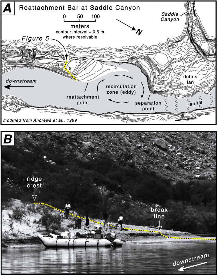 Figure 2 (192K) Figure 2 (192K)
Figure 2. Reattachment bar at Saddle Canyon. A) Topographic map of eddy-fan complex showing location of GPR profile in Figure 5. B) Photograph of sand bar also shows location of GPR profiles in Figures 5 and 6, which begin on the flat, emergent platform at right and cross the sandy ridge crest. Reattachment deposits accumulate in primary eddies at the downstream end of recirculation zones (Fig 2), where flow directions are reversed and flow velocities are low (Rubin et al., 1990; Schmidt and Graf, 1990). These morphology of these deposits resemble a sandy spit with a relatively high, central ridge or mound that projects upstream and a return channel on the landward side of the bar. Daily and seasonal fluctuations in discharge have significant impact on the morphology of reattachment bars, which respond to changes in the size of recirculation zones (Rubin et al., 1990). Substantial reworking occurs during infrequent large floods. The deposits first erode as flow velocity increases, and then build higher as the eddy enlarges and the reattachment point migrates downstream at peak flow. In this study, 817 m of GPR profiles were collected at three reattachment bars (Table 1). Data from Saddle Canyon, a reattachment bar at river mile 47, are presented here.
 Figure 3 (38K) Figure 3 (38K)
Figure 3. Aerial photograph of sand bar at Grapevine Rapid. Dashed lines indicate location of GPR profiles in Figure 4. Air photo from Northern Arizona University web page (http://vishnu.glg.nau.edu/gces/studysites.html)
Description of GPR UnitsGPR imagery consists of subsurface reflections that primarily arise when high-frequency electromagnetic signals encounter changes in degree of water saturation of sediment (Topp et al., 1980). These variations in water content are typically related to either changes in degree of saturation or differences in sediment texture. In this study, GPR reflections were recorded as shallow as 0.5 m and as deep as 7 m below the ground surface. We observed packages of relatively uniform reflections bounded by unconformities and recognized three GPR units following the methodology of Beres and Haeni (1991) and van Overmeeren (1998), a method that is similar to sequence-stratigraphic interpretation of seismic reflection data (e.g., Mitchum et al., 1977). The GPR units are defined on the basis of: 1) morphology of major bounding surfaces, 2) intensity, spacing, and coherence of internal reflections, 3) geometry or shape of a package of similar reflections, and 4) stratigraphic setting. We collected no cores and excavated no trenches in this project, but depend on earlier studies to confirm the GPR interpretations, where possible (Rubin et al., 1990, 1994a, 1994b).
Thickness of Sand DepositsGPR data show wide variation in the thickness of subaerial sand deposits at Saddle Canyon and Grapevine Rapid - sand bars located 47 miles and 81 miles, respectively, downstream of Lees Ferry (Fig. 1). At Grapevine Rapid, a thin veneer of sand (unit B) overlies talus and/or bedrock (unit A) beneath upstream parts of the sand bar (Fig. 4). There is significant relief on the upper surface of unit A and, where that buried surface is topographically low, the overlying sand deposits are at least 4 m thick. Due to attenuation below that depth, the base of the sand was not imaged, so the observed thicknesses are minimum values. No cores or trenches were available for ground truthing the imagery. Anima (personal communication, 1999) vibra-probed this sand bar in 22 locations and measured an average sand thickness of 2.54 m. Figure 4 (180K) Figure 4 (180K)
Figure 4. GPR profiles on sand bar at Grapevine Rapid, collected with 100 MHz antennas. A) GPR profile oriented parallel to river; downstream direction is to the right. Hyperbolic reflections indicate presence of buried boulders at positions 5-25 m. B) GPR profile oriented perpendicular to river channel. Vertical, dashed line indicates where profiles cross. See Figure 3 for location of profiles At Saddle Canyon, low-frequency GPR surveys indicate that sand deposits are at least 7 m thick beneath the crest of a sandy ridge (Fig. 5). The GPR reflection profiles here, as at Grapevine Rapid, provide only a minimum thickness because signal attenuation prevented detection of the base of the sand deposit. The base of the sand (unit B) is presumably underlain by talus or bedrock (unit A), but was not observed beneath the outer parts of the reattachment bar (i.e., closer to the main channel). It is unclear if unit A occurs in the more landward areas, where strong reflections may represent the base of the sand. Vibra-probing in 12 locations on this bar indicated an average sand thickness of 9.29 m (Anima, personal communication, 1999). Trenches or cores are needed to better interpret the origin of subsurface reflections in these two-dimensional profiles. 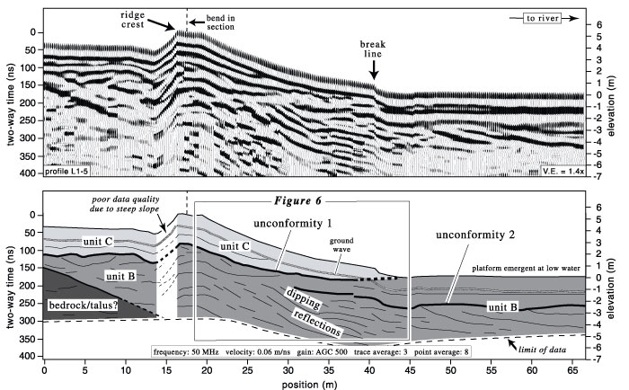 Figure 5 (88K) Figure 5 (88K)
Figure 5. GPR profile on sand bar at Saddle Canyon, collected with 50 MHz antennas. Profile is oriented perpendicular to river and crosses a linear ridge and return channel that were produced by the 1983 flood (see Figure 2). Depth of penetration varies from approximately 4 m on emergent platform (fully water saturated) to 7 m beneath ridge crest (drier sand). Beneath platform and flank of ridge, reflections gently dip toward the river (down to left) and are truncated by an angular unconformity. Box indicates section of profile that is replicated in Figure 6.
A Possible 1983 Flood DepositSand bars contain a partial record of floods in the Grand Canyon. Large floods typically scour an unconformity into older material, then bury that erosional surface with up to several meters of new sediment (Rubin et al., 1990, 1994b; Schmidt and Graf, 1990; Andrews et al, 1999). In 1983, a flood of over 100,000 cfs lasted two months and was the largest since completion of Glen Canyon Dam. The magnitude of the flood was representative of pre-dam events and strongly impacted the topographic and stratigraphic evolution of sand bars (Andrews et al., 1999; Schmidt and Graf, 1990). However, the full impact is poorly documented due to lack of pre-dam, baseline data. We believe that the strong reflector separating units B and C beneath the sandy ridge at Saddle Canyon (Figs. 5 and 6) is an erosional surface created by the large 1983 flood. Unit C probably represents material deposited later in the same flood cycle. This conclusion is based on comparison with interpretations of trench observations (Rubin et al., 1994b).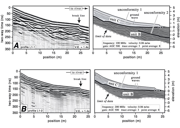 Figure 6 (92K) Figure 6 (92K)
Figure 6. GPR profiles on sand bar at Saddle Canyon, collected with A) 100 MHz and B) 200 MHz antennas along same trackline in Figure 5. Depth of penetration is less but these higher frequency surveys resolve finer details in upper part of section. Dipping reflections (down to right) are truncated by a strong, concave-up unconformity along flank of ridge. A smoothly curving, wedge-shaped deposit of sand (unit C) overlies the unconformity and is approximately 2 m thick in the center. The elongate, sandy ridge at Saddle Canyon is a relic feature that rises about 6 m above the average level of the river, and is separated from the canyon wall by a low-lying channel on its landward side (Fig. 2A). Topographically high parts of the bar were last submerged by flood waters in 1983, but the 1996 flood also had significant impact (Andrews et al, 1999). The 1996 flood lasted 7 days and initially caused intense scour, but was followed by generally depositional conditions. This sequence of events was also observed at Carbon Canyon, another reattachment bar located downstream, where "During the initial hours of the flood…the existing reattachment bar was extensively scoured and the return-current channel enlarged. The outer or channelward half of the reattachment bar…also was extensively scoured (Andrews et al., 1999, p. 125)." The maximum depth of erosion was about 3 m and, after the initial period of scour, more than 2 m of sand accumulated on both sides of the bar top, causing the crest of the bar to broaden considerably (Andrews et al., 1999). The possible flood deposit, or unit C (Figs. 5 and 6), at Saddle Canyon is similar in thickness and also drapes over the bar crest of the bar. It is underlain by a strongly reflective surface, which probably represents the period of initial scour. Similarly, Schmidt and Graf (1990) reported evidence of significant erosion by the 1983 high flows, and noted that "…major truncation surfaces … indicate that much of the sand in reattachment deposits is scoured, transported, and redeposited by high discharges (p. 21)." The well-documented response of sand bars in 1996 provides insight into the geomorphic effects of high-discharge events such as the 1983 flood, and aids our interpretation of GPR-based stratigraphic units.
Characterization of Alluvial Sediment with GPRDam construction on the Colorado River has reduced the supply of new sand to the Grand Canyon, so it is important to quantify and monitor the amount of sand that is stored in the system. This study demonstrates that GPR is an appropriate method for geophysical exploration of alluvial sediment in the Grand Canyon. Data collection is rapid and non-destructive, making GPR ideal for reconnaissance of large study areas and selection of sites for more intensive study. We recommend using antennas of different frequencies at sites of high value; replication of profile lines optimizes the utility of GPR imagery with a balance between penetration and spatial resolution of subsurface features. Information from trenches and cores are needed to confirm interpretations of GPR units, to correlate individual reflections with lithologic or textural changes, and to determine the depths and thicknesses of deposits.
Seismic reflection is similar in concept to GPR; both techniques depend on the detection of energy reflected from objects or discontinuities in the subsurface. Seismic methods operate at much lower frequencies (kHz range) than GPR (MHz range), and are able to map stratigraphic interfaces below the practical depths of GPR. The major advantage of seismic reflection is that water chemistry or the presence of clayey sediment does not adversely affect the transmission of acoustic energy. Data collection is slow and labor intensive, however, and the resolution of seismic data is much lower than GPR data. In addition, high-frequency GPR can resolve features less than 1 m below the surface, whereas ground waves often obscure the upper few meters of seismic reflection records. AcknowledgmentsWe thank David Topping and the Grand Canyon Monitoring and Research Center (GCMRC) for the logistical support that made this project possible. Ingrid Corson, Robin Dornfest, Ted Melis, Keith Kohl, and Hank Chezar assisted with the heavy lifting of field operations. We especially thank expert boatman Dan Dierker for sharing his knowledge of the river.References* This report is preliminary and has not been reviewed for conformity with U.S. Geological Survey editorial standards or with the North American Stratigraphic Code. Any use of trade, firm, or product names is for descriptive purposes only and does not imply endorsement by the U.S. Government. |
|||||||||||||||||||||||||||||||||||||
|
For more information, contact the PCMSC team.
Any use of trade, product, or firm names is for descriptive purposes only and does not imply endorsement by the U.S. Government. Suggested citation: Barnhardt, Walter, Kayen, Robert, Rubin, David, Minasian, Diane, 2001, The Internal Structure of Sand Bars on the Colorado River, Grand Canyon, as Determined by Ground-penetrating Radar: U.S. Geological Survey Open-File Report 01-425, https://pubs.usgs.gov/of/2001/0425/. U.S. Department of the Interior U.S. Geological Survey |

![]() U.S. Department of the Interior |
U.S. Geological Survey
U.S. Department of the Interior |
U.S. Geological Survey
URL: http://pubsdata.usgs.gov/pubs/of/2001/0425/intro.html
Page Contact Information: GS Pubs Web Contact
Page Last Modified: Wednesday, 07-Dec-2016 18:58:03 EST
