
USGS Professional Paper 1634
|
|||||||||||||||||||||||||||||||||||||||||||||||||||||||||||||||||||||||||||||||||||||||||||||||||
The Center for Applied Isotope Studies (CAIS) survey conducted at Lake Pontchartrain during September 1996 was designed to provide a reconnaissance characterization of the elemental constituents of surficial lakebed sediments, with resulting data used to delineate areas of greatest concern for further, more detailed study. Samples were collected using the CAIS-developed Continuous Sediment Sampling and Analysis System, or CS3, which samples the plume of surficial sediments generated by the movement of a towed sled along the sediment surface. The CS3 sled-mounted submersible pump delivers an uninterrupted stream of sediment slurry to a shipboard processor, where the fine sediment fraction is separated, dewatered, and deposited as a sample on a quartz fiber wafer. Using the USGS vessel G.K. Gilbert, more than 750 surficial sediment samples were collected over a 9-day period, using a close (approximately 1.9 km, or 0.75 mi) grid spacing that covered the entire Lake Pontchartrain area.
CAIS Rapid Survey Systems
The CAIS has been actively involved in the development and application of multisensor survey systems for data collection and mapping in aquatic environments for almost two decades. (Noakes and Harding, 1992; Noakes and others, 1991a). The CAIS systems consist of sensors, mounted on a towed sled, which continuously measure parameters at the sediment/water interface and collect surficial sediment samples as the vessel is underway. Shipboard instrumentation for data and sample processing, analysis, and storage enable real-time or near-real-time mapping of bathymetric, radiometric, elemental, sediment distribution, and water quality parameters. The CAIS rapid survey systems provide an effective means of rapid geochemical and environmental characterization of the sediment/water interface over large regions, and in many different types of aquatic environments. Operable at water depths of up to 100 m, the CAIS rapid survey systems permit data collection in most nearshore areas (including lakes, rivers, estuaries), including a large portion of the continental shelf.
The various CAIS sensor systems may be used individually or as a comprehensive survey package. The CS3 system used in the Lake Pontchartrain survey is the component specifically designed for continuous sample collection as the vessel is underway (Noakes and Harding, 1982; Noakes and others, 1985; Culp and others, 1991). Other sensor components that may be added include the Gamma Isotope Mapping System (GIMS), which uses a NaI(Tl) gamma radiation detector for the identification of naturally occurring or manmade radioisotopes present in seafloor sediments (Noakes and Harding, 1976; Noakes and others, 1991b). The GIMS shipboard spectrometer records gamma radiation levels for selected radionuclides, yielding an isotopic signature that is indicative of the sediment lithology (Emery and Uchipi, 1972). A water-quality data-logging device may also be integrated with the CS3 sediment slurry flow, providing continuous measurements of bottom water parameters including temperature, dissolved oxygen, conductivity, salinity, and pH (Noakes and others, 1991c). Synoptically collected bathymetric and navigational data facilitate the real-time or near-real-time generation of two- and three-dimensional profiles for many seafloor parameters when an immediate return of data is desired.
Continuous Sediment Sampling and Analysis System (CS3)
The components of the CS3 towed sled are configured in a cylindrical housing approximately 1.2 m in length and 28 cm in diameter (fig. 1). Umbilical connectors include a tow cable, a power cable, and sediment slurry transport hose. The sled is towed along the sea-floor surface, perturbing the sediments in its path to a depth of approximately 4-6 cm and forming a plume from which sediments are sampled. The CS3 is designed specifically for preferential sampling the fine sediments that are the ultimate sink for most aquatic contaminants and the primary site of the sorption reactions that govern their fate and persistence.
(click on any figure for a larger view)
Figure 1 |
Figure 2 |
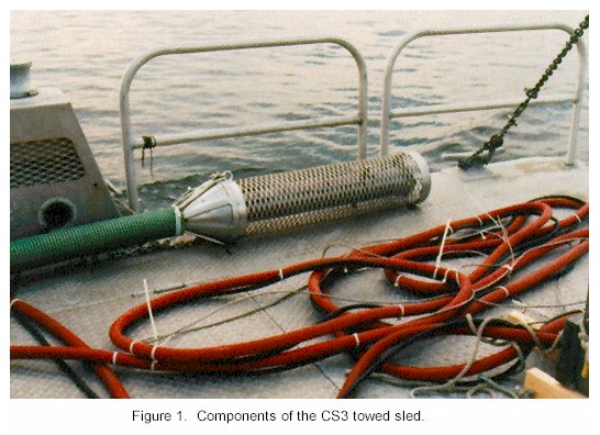
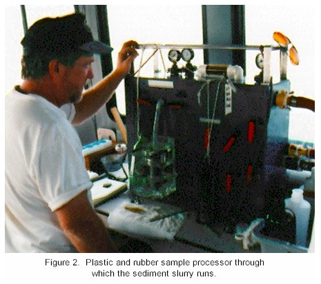
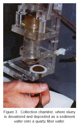
| The CS3 submersible pump, made of Delrin� plastic, delivers a continuous stream of surface sediments to the survey vessel via a rubber transport hose. The sediment slurry passes unobstructed through a sample processor consisting entirely of plastic and rubber parts (fig. 2), first flowing through a centrifugal cone where the fine sediment fraction (<200 �m) is selectively separated for sample analysis. Samples are collected on demand at intervals determined by the requirements of the survey. At the recommended towing speed of 3 knots, a maximum collection of approximately three samples per kilometer is possible. For sample collection, the continuously flowing fine fraction slurry is diverted to a collection chamber, where it is dewatered by vacuum filtration and deposited as a sediment wafer onto a quartz fiber wafer (fig. 3). | Figure 3 |
Samples are keyed to time and location and air-dried. Nondestructive elemental analyses for up to eight selected major and trace elements can be performed simultaneously aboard ship using a wavelength-dispersive X-ray fluorescence (XRF) spectrometer, or samples may be returned to the laboratory for a broader spectrum of analyses using an energy-dispersive XRF instrument.
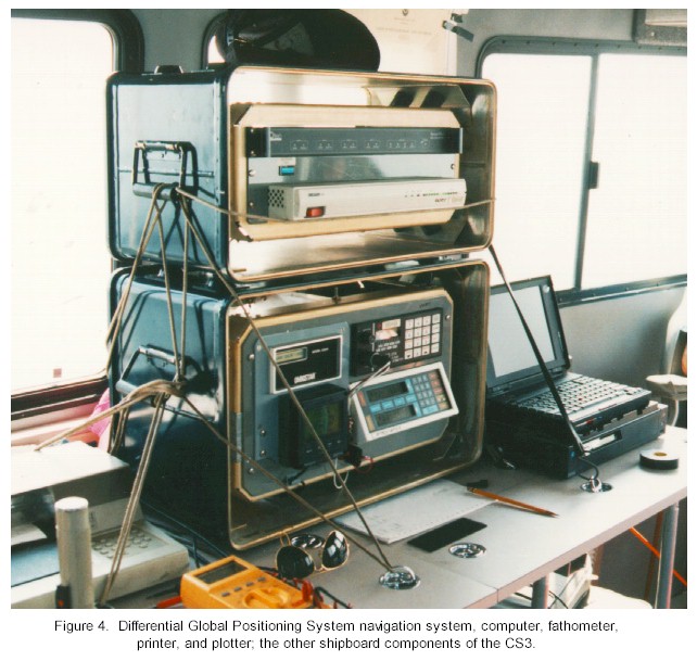
Other CS3 shipboard components include a differential Global Positioning System (DGPS) navigational system, portable computer, fathometer, printer, and plotter (fig. 4). Custom software compiles information from the fathometer and DGPS system each time a CS3 sample is collected. Survey transects and bathymetry may be viewed in real time on a color monitor (fig. 5). The data, along with the results of XRF analyses, are used to generate two- and three-dimensional profiles of bathymetry and elemental concentrations (fig. 6).
Figure 4 |
Figure 5 |
|
A minimum crew of three persons is required for CS3 operations. The actual time required for collection of 757 samples during the Lake Pontchartrain survey encompassed a period of approximately 80 hours over the 9-day survey. Normally, the CS3 may be operated around the clock for an efficient and time-minimizing schedule, but working time during the Pontchartrain survey was restricted to daylight hours due to the fuel requirements of the research vessel and to safety concerns associated with operations in the heavily trafficked lakefront area. The CS3 sled can be deployed by hand or by using a hydraulic crane. The sled is towed at variable speeds between 3 and 8 knots along designated transects. At a speed of 3 knots, the sled descends to the bottom, perturbing surficial sediments and enabling the collection of a sample on demand at the appropriate sampling station. Between sample stations, the ship's speed is increased to approximately 8 knots so that the sled was towed well above the sediment surface in the water column. This towing method is efficient and safe, as it permits a rapid coverage of survey transects while ensuring minimum opportunity for entanglement at the sediment/water interface. The method also reduced the possibility for cross-contamination of samples due to the cleansing effect from continuous pumping of water through the system between collection stations. Survey transects and CS3 sample collection stations are designated in advance to ensure a nonbiased distribution of data for preparation of the resulting elemental constituent maps (fig. 7). Sampling stations are located using DGPS. At each sample collection point, the sample number, navigational coordinates, and time of collection are recorded in the survey logbook and on computer diskette. The sediment wafer samples collected may be dried at ambient temperature and stored in stainless steel containers for transport to the analytical laboratory or may be dried using hot air and analyzed immediately using a shipboard XRF. The Lake Pontchartrain samples were returned to the CAIS laboratory, where a suite of 20 major and trace elements were analyzed using a Kevex 770 Analyst energy-dispersive XRF unit. This XRF instrument employs a variety of excitation conditions, secondary targets, and filters during each run to enhance analytical peaks. Selected target analytes and detection limits for the XRF instrument are presented in table 1. Figures 8(a) through 8(t) show the two- and three-dimensional elemental concentration maps generated as a result of the sediment mapping survey at Lake Pontchartrain. |
Figure 6
|
|
Figure 7
|

| Element | Reporting Unit | Detection Limit |
Mg |
wt % | 0.14 |
| Al | wt % | 0.05 |
| Si | wt % | 0.03 |
| S | wt % | 0.01 |
| K | wt % | 0.01 |
| Ca | wt % | 0.01 |
| Ti | wt % | 0.01 |
| Fe | ppm | 12 |
| Mn | ppm | 19 |
| Cr | ppm | 14 |
| Ni | ppm | 7 |
| Cu | ppm | 4 |
| Zn | ppm | 3 |
| Pb | ppm | 10-14 |
| Sr | ppm | 9 |
| Zr | ppm | 11 |
| Sn | ppm | 10 |
| Sb | ppm | 10 |
| Cd | ppm | 10 |
| Ba | ppm | 10 |
The CS3 sediment wafer samples are analyzed directly, without any treatment prior to analysis. Standard protocols for XRF analysis are observed, including detector calibrations for each batch of 15 samples using a reference disc of stainless steel and a reference monitor to ensure that the specific conditions required for secondary target excitation for the XRF unit did not vary from batch to batch. The reference monitor consists of sediment filter wafer samples that have been made up from NIST reference material SRM2704. For interlaboratory calibration, repeat analyses were performed for certified reference materials MESS-1, BEST-1, PACS-1, and USGS standard MAG-1. For the Lake Pontchartrain survey, four separate samples from widely spaced portions of the lakebed were split and analyzed in duplicate with the remainder of each split sent to the USGS for analysis.
Detection limits are quoted at 3s over background and were determined using NIST 2704 standard reference material.
|
|
||||||||||||
Appendixes
The precision and accuracy determined by the replicate analyses on the 2704 NIST reference standard are presented in appendix A. Also included in appendix A are steps taken to normalize the data to achieve consistent concentration totals and results of an interlab sample comparison utilizing analytical methods other than the XRF methods used for this study. It was determined that the elemental concentration would be normalized to 90% total concentration to minimize sample variability. XRF data may not directly correlate with data compiled by other methods, but the results of the interlab sample comparison showed that the XRF data related the same relative patterns in elemental concentration. The sample locations, water depth, and elemental analyses from the 1996 sediment mapping survey are found in appendix B. More recent data, including sample stations, water depth, and elemental analyses, from a follow-up survey conducted in the summer of 1997 are found in appendix C. The two-dimensional maps generated by the 1997 data are displayed in the 1996-97 comparison figures (figs. 9A-9E).
Appendixes B and C are tables available here in both Microsoft Excel and Corel Quattro Pro for viewing or downloading:
| Microsoft Excel versions | Corel Quattro Pro versions | |
| 1996 Lake Pontchartrain XRF Elemental Data | Appendix B | Appendix B |
| 1997 Lake Pontchartrain XRF Elemental Data | Appendix C | Appendix C |
CAIS, 1997, Quality assurance project plan for areal mapping of sediment chemistry at Lake Pontchartrain, Louisiana: Submitted to Lake Pontchartrain Basin Foundation for approval on 7/15/97.
Culp, R.A., Noakes, S.E., and Noakes, J.E., 1991, Rapid sediment sampling and analysis system: Proceedings of the 23rd Annual Offshore Technology Conference, Houston, Texas, May 6-9, 1991, v. 1., p. 543-551.
Emery, K.O., and Uchipi, A., 1972, Western Atlantic Ocean: American Association of Petroleum Geologists Memoir No. 17.
Noakes, J.E., Culp, R.A., and Spaulding, J.D., 1985, Continuous sediment sampling system for trace metal surficial sediment studies, in Zirino, A., ed., Mapping strategies in chemical oceanography: American Chemical Society Advances in Chemistry Series 209, Washington, DC, p. 99-209.
Noakes, J.E., and Harding, J.L., 1976, Locating offshore minerals by natural radioactive measurements: Marine Technology Society Journal, v. 8, no. 5, p. 36-39.
Noakes, J.E., and Harding, J.L., 1982, A continuous seafloor sediment sampler (CS�): Proceedings of the 14th Annual Offshore Technology Conference, Houston, Texas, May 3-6, 1982, no. 14, v. 2, p. 731-735.
Noakes, J.E., and Harding, J.L., 1992, Overview of nuclear techniques for marine mineral survey and environmental assessment, in Geyer, R.A., ed., Handbook of geophysical exploration at sea: Ann Arbor, Michigan, CRC Press, p. 311-321.
Noakes, J.E., Noakes, S.E., Culp, R.A., and Spaulding, J.D., 1991a, Seafloor surveillance systems for environmental and marine mineral exploration: Proceedings of Oceans ‘91, Honolulu, Hawaii, October 1-3, 1991, v. 2, p. 677-680.
Noakes, S.E., Noakes, J.E., and Spaulding, J.D., 1991b, Gamma sled for seafloor lithology survey: Proceedings of the 23rd Annual Offshore Technology Conference, Houston, Texas, May 6-9, 1991, v. 1, p. 403-410.
Noakes, J.E., Noakes, S.E., and Culp, R.A., 1991c, Comparison of data logger parameters aboard ship and towed on the seafloor: Proceedings of the 23rd Annual Offshore Technology Conference, Houston, Texas, May 6-9, 1991, v. 1, p. 411-416.