Scientific Investigations Report 2006–5060
U.S. GEOLOGICAL SURVEY
Scientific Investigations Report 2006–5060
Modifications were made to CE-QUAL-W2 to enable it to blend withdrawals from more than one lake outlet, and set the depth of any adjustable-depth outlets, in order to meet a user-specified time series of target temperatures for water released from a reservoir. In this way, the model can be used to (1) assess whether certain downstream temperature targets can be met under various structural and operational scenarios, (2) assess the effects of using different types of outlets, either singly or in combination, and (3) assess the effects of specifying different temperature targets, among other things. Some of these objectives, such as using multiple fixed outlets to meet a downstream temperature target, could have been accomplished with the model previously, but only by running the model multiple times and iterating on the flow rates from each outlet. The changes added by the USGS modeling team allow these tasks to be accomplished in a single model run, because the necessary operational changes are done automatically.
Several additions were made to the model in order to implement this new ability to blend withdrawals from multiple outlets. The most important of these changes are listed below.
When flows from two outlets are blended to meet a target temperature, determining the flow from each outlet is a straightforward calculation. The total release rate from the withdrawal group is known because it was set by the user in the model’s withdrawal flow file. The target temperature also is known. If more than two outlets are available within a withdrawal group, the model’s rules, described above in item 5, are used to select the two active outlets. The depth of each outlet is known, and therefore the simulated water temperature in the lake at the depth of each outlet also is known. The flows in each outlet, then, are calculated using the following equations. Conservation of energy requires that:
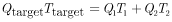 ,
(A1)
,
(A1)
where
 |
is |
the total release rate, |
 |
is |
the target temperature, |
 |
is |
the flow in the first outlet, |
 |
is |
the temperature associated with the first outlet, |
 |
is |
the flow in the second outlet, and |
 |
is |
the temperature associated with the second outlet. |
Conservation of mass requires that:
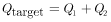 .
(A2)
.
(A2)
Determining the value of ![]() ,
therefore, is a simple matter of substituting
,
therefore, is a simple matter of substituting ![]() with (
with (![]() )
and solving for
)
and solving for ![]() ,
which leaves:
,
which leaves:
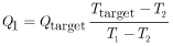 .
(A3)
.
(A3)
Once ![]() is found, the value of
is found, the value of ![]() is determined through application of equation A2. Note that equation A3 applies
only when the target temperature is between the temperatures at the two selected
outlets; this is why the outlet selection rules outlined above were crafted
to select the two outlets that can draw water from as high and as low in the
water column as possible, thus maximizing the available temperature difference
is determined through application of equation A2. Note that equation A3 applies
only when the target temperature is between the temperatures at the two selected
outlets; this is why the outlet selection rules outlined above were crafted
to select the two outlets that can draw water from as high and as low in the
water column as possible, thus maximizing the available temperature difference
![]() .
.
If the target temperature is greater or less than both of the outlet temperatures, the model assigns all flow to the outlet having the temperature closest to the target temperature. If the two outlet temperatures are identical, then flow is split equally between the two outlets only if those temperatures also equal the target temperature; otherwise, a higher target temperature results in all flow being assigned to the higher outlet while a lower target temperature results in all flow being assigned to the lower outlet.
For more details on how the model implements this blending strategy, the ultimate source of information is the model’s source code, which is available online at the project website: http://or.water.usgs.gov/tualatin/hagg_lake/scenarios/. Note that the model code also implements a set of “avoidance” algorithms in which “avoidance rules” may be set by the user and consulted by the model when making decisions concerning which outlets to choose for blending. For example, the user could tell the model to avoid withdrawing any water where the dissolved oxygen is less than a certain concentration, and/or where the ammonia exceeds some concentration. No avoidance rules were used in the Hagg Lake model runs, though they may be used in future scenarios. At this point, the avoidance algorithms are fairly simple and could be improved in the future.
In addition to the algorithms that take care of the blending details, new output options were added to the model that aid in documenting how the blending was done. Such output includes the actual flow rate from each of the withdrawals involved in blending, their elevation, and the layers in the model from which the water ultimately was withdrawn.
For more information about USGS activities in Oregon, visit the USGS Oregon Water Science Center home page.

![]() U.S.
Department of the Interior | U.S. Geological
Survey
U.S.
Department of the Interior | U.S. Geological
Survey
Persistent URL: https://pubs.water.usgs.gov/sir20065060
Page Contact Information: Publications
Team
Page Last Modified:
Thursday, 01-Dec-2016 19:05:10 EST
