

Framework Developed for Geomorphic Mapping of Fern Ridge Lake, Oregon, 2023
Links
- Document: Report (9.8 MB pdf) , HTML , XML
- Data Release: USGS data release - Geomorphic Mapping of Fern Ridge Lake, Oregon, 2023
- NGMDB Index Page: National Geologic Map Database Index Page (html)
- Download citation as: RIS | Dublin Core
Acknowledgments
This study was prepared in cooperation with the U.S. Army Corps of Engineers (USACE). We are thankful for the support from Molly Casperson, Shawna Umlor, Carley Smith, Brittany Spoto, and Gwendolyn Jones from USACE. Theresa Wriston and J.D. Lancaster (Desert Research Institute) provided valuable insights on reservoir processes at Fern Ridge Lake. Maxwel Schwid, Brandon Overstreet, Jim O’Connor (U.S. Geological Survey [USGS]) and Laurel Stratton Garvin (formerly USGS, Oregon Water Resources Department) contributed to the geomorphic mapping framework with expertise on reservoir processes and Willamette River Basin geomorphology. Maxwel Schwid, Brandon Overstreet, and Julia Grabowski (USGS) assisted with field work and development of datasets that underlie the Fern Ridge Lake geomorphic mapping.
Abstract
The construction and operation of large reservoirs in the Willamette River Basin, Oregon, influences important cultural, biological, and other natural or economic resources in affected river corridors. The present-day landforms and cover within the reservoirs have been shaped by a variety of processes, including the pre-dam valley setting and geomorphic processes related to dam operations. Maps of reservoir geomorphic process domains, landforms, and cover provide a foundation for understanding how erosion and deposition processes in or near the reservoirs may affect cultural resources. Detailed geomorphic mapping of Fern Ridge Lake in 2023 provides a basis for evaluating geomorphic processes and patterns of sediment transfer within the reservoir. These processes are related to geomorphic and hydroclimatic conditions as well as annual lake level fluctuation for seasonal flood-control operations. This geomorphic mapping also provides an inventory of existing landforms from which to evaluate the spatial and temporal geomorphic change over time. Digital maps based on high-resolution digital surface models and orthophotographs acquired during low-pool conditions in 2023 extend over an area of about 30 square kilometers (km) upstream of the Fern Ridge Dam. The mapping framework has 3 main components consisting of several subtypes: 5 process domains, 18 landforms, and 7 cover categories. The overarching classification structure is tied to the process domains, which correspond to dissimilar regions of the reservoir that have distinct landforms and broadly similar suites of geomorphic processes. This document describes the geomorphic mapping framework for the reservoir at Fern Ridge Lake and provides mapping unit descriptions including delineation criteria, hypothesized formation processes inferred from remote-sensing and field observations and the literature, and relevance during drawdown operations.
Introduction
The construction and operation of large reservoirs in the Willamette Valley, Oregon (fig. 1), has influenced important cultural, biological, and other natural or economic resources in affected river corridors. The processes that shaped these valley bottoms prior to dam construction in the mid-20th century and the altered conditions resulting from dam construction and operations in the ensuing decades have shaped the present-day landforms and cover within the reservoirs. Maps of reservoir landforms, cover, and geomorphic process domains provide a foundation for understanding how erosion and deposition processes within or near the reservoirs may affect cultural resources. Detailed geomorphic mapping of Fern Ridge Lake in 2023 (Bervid and Keith, 2025) enables evaluation of geomorphic processes and patterns of sediment transfer within Fern Ridge Lake. The mapping framework consists of three categories:
-
• Process domains are applied to groupings of landforms with broadly similar formational or functional processes.
-
• Landforms within the Fern Ridge Lake primarily consist of features interpreted to have been formed predominantly by reservoir processes, though pre-dam geomorphic processes and surfaces provide an important influence on the evolution of the reservoir landforms after dam construction.
-
• Cover includes multiple substrate categories generalized by grainsize for landforms, infrastructure, water, or vegetation.
This mapping effort was initiated to inform U.S. Army Corps of Engineers (USACE) cultural resources management (CRM) but can also inform other issues such as dam operations, sediment management, as well as ecological and natural resources management of other reservoir conditions and processes.
Study Area
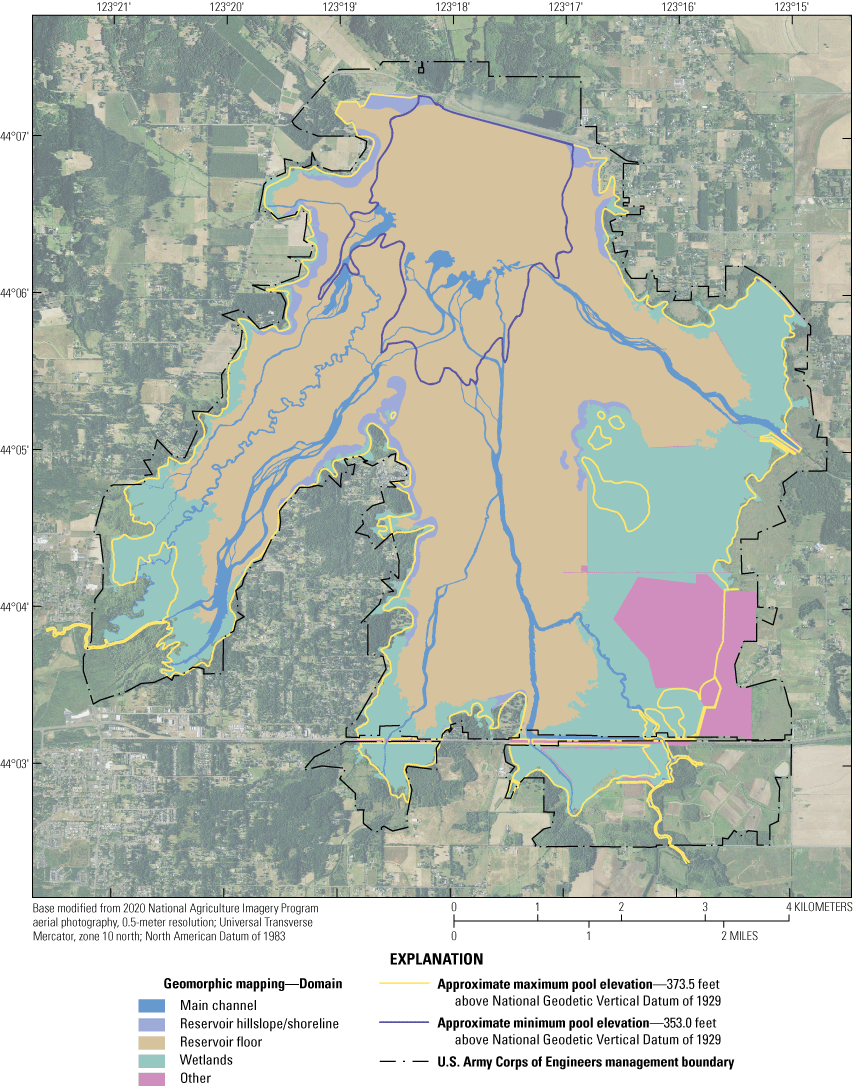
Fern Ridge Dam, located west of Eugene, Oregon (figs. 1, 2) is 1 of 13 dams operated by USACE within the Willamette Valley Project (WVP) and impounds about 36 square kilometers (km2; 9,000 acres) of Fern Ridge Lake. The USACE reservoir-management area bounds the perimeter of the reservoir, typically extending just beyond the maximum conservation pool elevation of 114 m (373.5 feet [ft]). The Oregon Department of Fish and Wildlife (ODFW) manages about 24 km2 (5,831 acres) of habitats (primarily wetlands, but also grassland and woodlands) for several native species within the Fern Ridge Wildlife Area (FRWA, established in 1957), most of which falls within the boundary of USACE’s Fern Ridge Lake (Oregon Department of Fish and Wildlife, 2020). The FRWA units are managed with a combination of active and passive management strategies; see Oregon Department of Fish and Wildlife (2020) for additional details The primary purpose of WVP dams and reservoirs is flood control (or flood-risk management); although, other authorized purposes at Fern Ridge Dam (and other reservoirs) include water quality improvement, irrigation, fish and wildlife habitat, and recreation. USACE dam operators manage Fern Ridge Lake levels to meet these and other authorized purposes. Construction of the dam and subsequent operations have transformed the Long Tom River, Coyote Creek, other tributaries, and surrounding landscape from a broad river valley carved by meandering streams into a broad, shallow reservoir shaped by complex patterns of sediment erosion, deposition, and transport. Reservoir lake levels can fluctuate annually by more than 6 meters (m; 20 ft; fig. 2) exposing about 30 km2 (7,400 acres) of lakebed between minimum (108 m or 353.0 ft NGVD29) and maximum conservation pool (114 m or 373.5 ft NGVD 29) levels. As a result of fluctuating lake levels, the primary locations and mechanisms of erosion and deposition in Fern Ridge Lake vary seasonally.
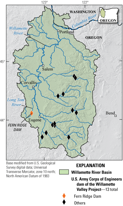
Major streams and U.S. Army Corps Willamette Valley Project dams within the Willamette River Basin, Oregon.
![Primary stream network (as modeled by the National Hydrography Dataset, NHDPlus High
Resolution) and approximate minimum (353 feet above the National Geodetic Vertical
Datum of 1929 [NGVD 29]) and maximum (373.5 feet above NGVD 29) pool levels at Fern
Ridge Lake, Oregon.](https://pubs.usgs.gov/dr/1215/images/dr1215_fig02.png)
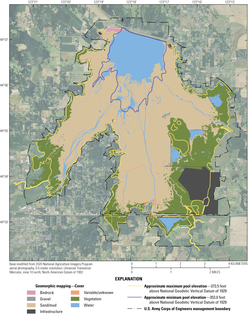
Primary stream network (as modeled by the National Hydrography Dataset, NHDPlus High Resolution) and approximate minimum (353 feet above the National Geodetic Vertical Datum of 1929 [NGVD 29]) and maximum (373.5 feet above NGVD 29) pool levels at Fern Ridge Lake, Oregon.
Purpose and Scope
This document describes geomorphic mapping for USACE’s Fern Ridge Lake, a reservoir impounded by Fern Ridge Dam. The geomorphic mapping framework provides unit descriptions including delineation criteria, hypothesized formation processes inferred from remote-sensing, field observations, previous studies, and conditions during seasonal flood-control drawdown operations. The mapping focuses on the USACE reservoir-management area between minimum and maximum pool levels that is exposed annually during seasonal flood-control operations. Digital maps (Bervid and Keith, 2025) were produced to show reservoir conditions in the Fern Ridge Lake, Oregon, extending over an area of about 30 km2 upstream of the Fern Ridge Dam (figs. 1, 2). Detailed geomorphic mapping of reservoir landforms and cover provides a basis for evaluating geomorphic processes and patterns of sediment transfer within Fern Ridge Lake. This mapping also provides an inventory of existing landforms, as of 2023, from which to evaluate the spatial and temporal geomorphic changes in the future.
Geomorphic Mapping Methods
General Mapping Protocols and Considerations
Geomorphic mapping within Fern Ridge Lake was based primarily on datasets developed from January and February 2023 aerial photography (Schwid and others, 2025) using approaches similar to Keith and Mangano (2020). Aerial photographs were processed with AgiSoft Metashape software to develop DSMs and orthophotographs from which mapping was based; datasets are publicly available at about 10-cm resolution for the whole reservoir and at about 5-centimeter (cm) resolution for substantial portions of the reservoir along the Long Tom River and Coyote Creek arms (Schwid and others, 2025). Lake levels at the time of imagery acquisition were within 0.85 m (2.8 ft) of minimum pool elevation (353.0 ft; table 1). Geomorphic mapping primarily used orthophotographs; DSMs and mapping derivatives (slope, curvature maps) were also used to delineate and interpret process domains, landforms, and cover as needed.
Table 1.
Daily lake levels (U.S. Geological Survey reports daily lake data for Fern Ridge Lake as the observation at midnight, in feet above the National Geodetic Vertical Datum of 1929) for Fern Ridge Lake, Oregon, and streamflows (mean daily, in cubic feet per second) into and out of the reservoir gaged on the Long Tom River on days of aerial photograph acquisition.[Abbreviations: USGS, U.S. Geological Survey; OR, Oregon]
Geomorphic mapping within Fern Ridge Lake followed generalized approaches and protocols developed for similar mapping at Fall Creek Lake (Keith and Stratton Garvin, 2021; Keith and others, 2024) which is also operated by USACE as part of the WVP; many of the descriptions of process domains, landforms, and cover were taken directly from or modified from the previous mapping schema. Landforms visible in orthophotographs were outlined using a polyline feature class. Outlines were drawn to represent the landform as seen at a scale of 1:500 (screen:ground units) along the main river channels and at a scale of 1:1,500 throughout the rest of the reservoir. All landforms within the study area greater than 100 square meters were digitized. ESRI geodatabase topology rules of “Must not have dangles” and “Must not overlap” were used for editing, which required that all feature polylines must not occupy the same space. A point feature class was used to label each landform (including process domain and cover) as delineated by polylines (table 2). Landform delineation as well as the assigned process domain, landform, and cover attribute assignments were verified by project team members to ensure consistent delineation and attribute assignment throughout the study area. The linework delineating landforms and point attribute labels were converted to polygons with the “Feature to polygon” tool within the ArcGIS “Data Management” tools.
Geomorphic Mapping Structure
The geomorphic mapping framework was developed to identify reservoir landforms, the geomorphic processes shaping those landforms, and hypotheses on the underlying controls on those processes (primarily, lake level fluctuations related to dam operations, hydroclimatic conditions, and pre-existing geomorphic conditions of the reservoir). The mapping framework has 3 main components: process domains (5), landforms (18) and cover classification (7) (table 2). The over-arching classification structure is tied to the process domains, which classify regions of the reservoir that each have distinct landforms and broadly similar suites of geomorphic processes (tables 2, 3). Within the broad process domains of the reservoir, individual landforms are mapped and the cover for each landform is also specified. Mapping at Fall Creek (Keith and Stratton Garvin, 2021; Keith and others, 2024) showed that landforms and cover provide information about (1) sediment regime and geomorphic processes that formed the landform, (2) general context for the sediment sizes that may be mobilized during seasonal flood-control operations, and (3) susceptibility to erosion and re-distribution (table 4). Interpreting processes of sedimentation and erosion from reservoir landforms and cover supports evaluation of the evolution of Fern Ridge Lake during typical lake conditions and seasonal flood-control operations. Mapped landforms and cover mirror a complex history of alternating depositional and erosional processes. Similar to Fall Creek Lake (Keith and Stratton Garvin, 2019, Keith and others, 2024) the mapping reveals a dynamic reservoir environment influenced multiple processes that may change between lacustrine conditions dominant at high lake levels and fluvial conditions more dominant at lower lake levels (table 4).
Table 2.
Summary of and abbreviated descriptions for geomorphic mapping for Fern Ridge Lake, Oregon, including process domains, landforms, and cover categories.Table 3.
Matrix indicating which landforms are mapped within each process domain for Fern Ridge Lake, Oregon, in 2023.[Abbreviations: X, indicates presence of landform within a domain; --, not present]
Table 4.
Conceptual model linking reservoir landforms with generalized sediment regimes for low and high pool levels at Fern Ridge Lake, Oregon, in 2023.[Low pool corresponds to minimum conservation pool level (353.0 feet above the National Geodetic Vertical Datum of 1929 [NGVD 1929]), and high pool corresponds to maximum conservation pool level (373.5 feet NGVD 1929).]
Geomorphic Process Domains
Process domains (table 2; fig. 3) include groups of landforms encompassing regions of the reservoir shaped by broadly similar formational or functional processes. The Process Domain Concept for rivers characterizes inter-related disturbance processes, morphologies, and habitats typically at the valley to reach-scale (Montgomery, 1999) but was generalized and adapted for mapping reservoirs at Fall Creek Lake (Keith and Stratton Garvin, 2019, 2021; Keith and others, 2024) and Fern Ridge Lake (Bervid and Keith, 2025; this report). The reservoir process domains represent groups of landforms within the reservoir that share similar conditions and seasonally varying processes. For example, the main channel process domain is largely subject to lacustrine processes at high pool levels; at lower pool levels, the main channel domain is dominated by fluvial processes whereby channelized streamflows can transport sediment and other materials farther downstream. The main channel process domain consists of several landforms, including the wetted channels, bars, banks, and levees (table 3). The process domains are not directly delineated but are assigned to mapped, commonly adjacent, landform and cover polygons to characterize broader-scale processes.
Geomorphic process domains (see table 2) mapped within Fern Ridge Lake, Oregon.
Main Channel(s)
The main channel process domain (table 2; fig. 3) consists of landforms that actively convey streamflow during relatively low pool conditions during seasonal drawdowns for flood control. The main channels are generally larger in size and extent than other channeled landforms that are included within other process domains. For Fern Ridge Lake, these principal channels include Amazon Creek, Middle, West, and mainstem Coyote Creeks, Long Tom River, Hannavan Creek, and Inman Creek. Key landforms comprising the main channel process domain of Fern Ridge Lake includes wetted channels, channel banks, and alluvial landforms such as bars. The main channel areas of the reservoir may have water in them, but other landforms are typically exposed (not inundated) when pool levels are at or below about 353 ft (NGVD 1929).
Reservoir Hillslope
The reservoir hillslope process domain (table 2; fig. 3) encompasses the relatively steep valley walls or reservoir margins that extend from edge of the USACE reservoir management area downwards to a prominent or subtle break in slope at the lower gradient reservoir floor. It may include wave cut topography, near vertical banks of exposed rock or sediment, rills, small streams, or be covered in vegetation (or obscured from vegetation in orthophotographs). At Fern Ridge Lake, the reservoir hillslope process domain is commonly mapped as a narrow band of shoreline along the outer perimeter of the lake. Landforms in this process domain may show evidence of wave-cut terracettes (Goudie, 2014, for example; ledges that, for Fern Ridge Lake, vary in height [risers, on the order of 1 cm to 1 m] and width [treads, on the order of 10 cm to a few meters]) on relatively steeper hillslopes with substrates that permit formation.
At Fall Creek, the reservoir hillslope process domain may also have herbaceous vegetation on high-elevation surfaces that have not been inundated for an extended amount of time. However, vegetation is not necessarily a distinguishing factor of hillslope at Fern Ridge Lake because shallow water levels across much of the reservoir at high pool levels and broad exposed areas at low pool permit the growth of emergent macrophytes and herbaceous vegetation across the reservoir floor.
Reservoir Floor
The reservoir floor process domain (table 2; fig. 3) generally includes a broad, low gradient suite of planar surfaces that collectively form the reservoir floor and extend from valley-edge hillslope areas to and between the main channels. In other USACE WVP reservoirs (for example, Fall Creek Lake as mapped by Keith and Stratton Garvin [2021]), broad reservoir floors include marginal floor along the reservoir boundary (mapped as ‘littoral reservoir floor’), the main paleo valley-bottom and adjacent terraces (mapped as ‘pelagic reservoir floor’), and isolated floor perched within the bounds of the reservoir hillslope process domain (also mapped as ‘pelagic reservoir floor’). However, within Fern Ridge Lake, the entire reservoir floor (at least the part exposed at low pool) is under relatively shallow waters at full pool and the transition between littoral-pelagic zones was not defined for this study. The reservoir floor process domain most commonly includes areas of former main channel floodplain and terraces. The main transition from reservoir hillslope to reservoir floor is primarily at a prominent break in slope, but in some instances the break is more gradual and difficult to define. At Fall Creek Lake, the transition from reservoir hillslope to reservoir floor can be distinguished by conditions such as the appearance of wave-cutting features, sediment color and tone or type, or the presence of exposed tree stumps and roots. Exposed tree stumps indicate lack of burial by sediment, whereas reservoir floor features display tree stumps that are partially buried. Likewise, channels and gullies in the Fall Creek reservoir hillslope process domain commonly transition to fans or distributary landforms on the reservoir floor. However, at Fern Ridge Lake, the transition from reservoir hillslope to reservoir floor process domain is less apparent in orthophotographs than at Fall Creek Lake and geomorphic mapping requires review of supplemental information such as digital surface models. Shallow water levels across much of the reservoir at high pool levels and broad exposed areas at low pool permit the growth of emergent macrophytes and herbaceous vegetation across the reservoir floor.
Wetlands
Expanding upon the Fall Creek Lake reservoir geomorphology mapping framework (Keith and Stratton Garvin, 2021; Keith and others, 2024), an additional process domain was added to the Fern Ridge Lake mapping to encompass wetland areas (predominantly marshlands along the Fern Ridge Lake shoreline; Oregon Department of Fish and Wildlife, 2020). Because wetlands have historically been, and presently are a dominant feature at Fern Ridge Lake, and because these areas warrant additional considerations for cultural resources management, the wetlands process domain was included in this study, even though the boundary between wetlands and adjacent reservoir floor or hillslope process domains may be diffuse. The wetlands process domain (table 2; fig. 3) encompasses a region where the suite of hydrogeomorphic processes, largely driven by abundant, dense vegetation cover, differ from reservoir floor and hillslope process domains. The majority of the wetlands process domain includes the low-gradient, densely vegetated margins along the reservoir edge that can become shallow, partially inundated wetlands at higher pool levels and commonly contain ponds that remain filled with water at lower pool levels. The wetlands process domain may also include ponds, upstream reaches of tributary channels, higher surfaces that are less frequently or rarely inundated, and other small features related to drainage along the edge of the wetlands. This process domain is most prominent along the southern margins of the reservoir where primary tributaries (mapped as main channels) enter the reservoir and within and adjacent to areas managed by ODFW. Smaller areas mapped as wetlands also occur in bays and coves in other regions along the reservoir edge.
Other
The other process domain encompassed multiple landforms that did not appropriately fall into another process domain category because hydrogeomorphic processes that shaped collective landforms were likely not or only partially driven by dam operations in most of Fern Ridge Lake. For example, some ponds and habitat areas constructed and managed by ODFW are included in this process domain (table 2; fig. 3) because lake levels, inflows, and sediment sources are unlike those occurring in the main area of the Fern Ridge Lake. However, not all ODFW land was classified as the other process domain.
Landforms Mapped within the Fern Ridge Lake Study Area
Descriptions and criteria for landform mapping rely heavily on the definitions in Keith and Stratton Garvin (2021) and Keith and others (2024). Although specific criteria for identifying and delineating landforms are described below, decades of overprinting and landform evolution results in a continuum of landforms that occasionally do not fit neatly into individual mapping categories. For example, some tributary channels, relict channels and swales, drainage channels, drawdown channels, basins, and reservoir floor landforms have been subject to different geomorphic processes prior to and since dam construction as pool levels have fluctuated. As a result, the 2023 aerial imagery reveals that some of these landforms show characteristics of other past landforms. Bervid and Keith (2025) attempted to map landforms consistently across the basin, but it is possible some landforms would have been interpreted different by other mappers.
Landforms within the Fern Ridge Lake (table 2; fig. 4) primarily consist of features interpreted to have been formed predominantly by reservoir processes and human activities. Eighteen landform categories were identified for this Fern Ridge Lake mapping effort. Mapping categories include several types of channel features, two types of banks, wetlands, reservoir floor, and hillslopes, as well as other human-made features. Mapped reservoir landforms within the Fern Ridge Lake primarily consist of features interpreted to have been altered by reservoir processes, though pre-dam geomorphic processes and surfaces provide an important influence on the evolution of the reservoir landforms after dam construction. These landforms are also affected by dam operations and other natural and human activities that occur throughout the year. Seasonal flood-control operations create large (greater than 20 ft [6.1 m]) lake level fluctuations that influence locations of sediment deposition. Table 4 summarizes the interpreted sediment regimes that are dominant at minimum (353 ft; NGVD 29) and maximum (373.5 ft; NGVD 29) pool levels. In addition to the landforms shaped prior to and modified by dam construction, landform mapping also include human made features such as ‘fill and infrastructure’ and ‘cut’). The landform descriptions, delineation criteria, inferred formation processes, and inferred geomorphic relation to operational lake levels, as well as relevant figure numbers, are generally organized into the following subsections:
-
1. General description and surface expression or distinguishing feature;
-
2. Criteria for linework digitization and landform delineation (for example, break in slope, width in meters, inundation) or elaboration on distinguishing features;
-
3. Inferred formation processes;
-
4. Inferred geomorphic significance in relation to dam operations; and
-
5. Examples (links to figures where landforms are shown throughout report).
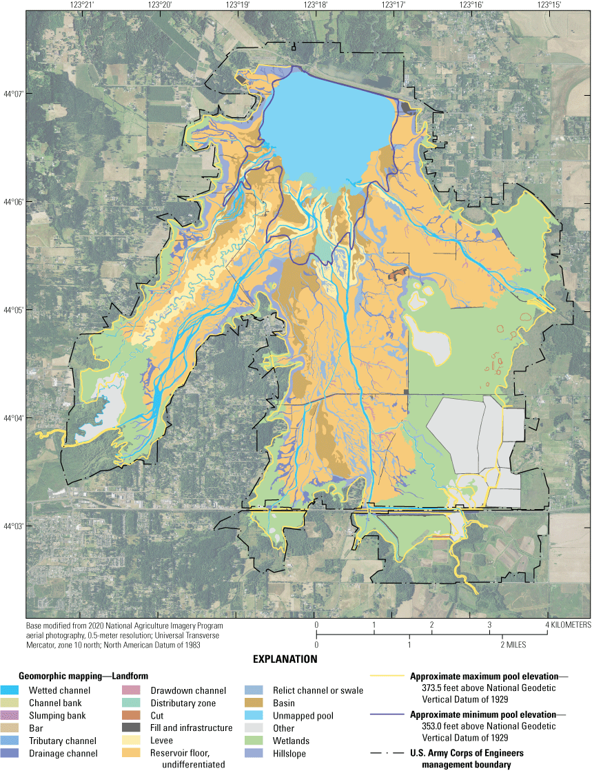
Landforms mapped within Fern Ridge Lake, Oregon. See table 2 for explanation of landform descriptions.
Bar
General description and surface expression or distinguishing feature—Bars within Fern Ridge Lake are streamlined landforms located along the main channels that are occasionally composed of gravel, though sand-and finer sized sediment is more typical. These landforms appear to be actively accumulating or eroding when the reservoir is drawn down to minimum pool elevation. Bars are recently active landforms formed through fluvial depositional or transport processes; they represent recent sediment transport and deposition by fluvial processes as opposed to lacustrine processes. Most mapped bars are relatively small (a few hundred square meters), though some bar forms are larger and may be more representative of reservoir floor/floodplain in the braided sections of Hannavan Creek, Long Tom River, and Amazon Creek. Bars in the meandering section of the Long Tom River and Coyote Creeks are sparse.
Criteria for linework digitization and landform delineation or elaboration on distinguishing features—Only parts of bars above the water surface are delineated. In many cases, top elevations of the bars rise less than about 0.5 m above the water-surface elevation (from 2023 topography) and show signs of sediment mobilization and deposition along their edges and surfaces. Some bars form along stable features, such as tree stumps, bridge pilings, or stable reservoir flood within the wetted channel.
Inferred formation processes—Bars are recently active landforms formed through fluvial depositional processes with free-flowing channel conditions during periods of lowered lake levels.
Geomorphic significance in relation to dam operations—Reworked and active during lower pool levels when bar location coincides with fluvial processes.
Examples—Figures 4, 5, 11, and 13
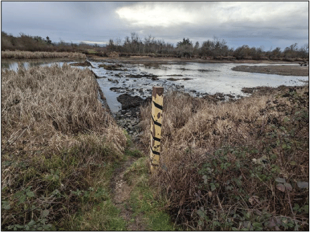
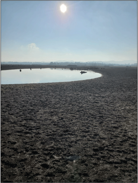
Examples of bar (right side of photograph) downstream of weir structure on Amazon Creek Diversion Channel mapped within Fern Ridge Lake, Oregon. Photograph taken by Heather Bervid, U.S. Geological Survey, January 31, 2024.
Bank—Channel Bank
General description and surface expression or distinguishing feature—Channel banks or channel margins within Fern Ridge Lake are defined as sloping margins along the alluvially formed channel that confines discharge during the low-flow full reservoir drawdown (definition modified from Osterkamp [2008] and Keith and Stratton Garvin [2021]) and are only mapped along the wetted channels where they meet minimum mapping criteria. Slumping banks are mapped as a separate landform unit.
Criteria for linework digitization and landform delineation or elaboration on distinguishing features—Channel banks were delineated separately from the main wetted channels where distinct channel banks were clearly visible. A second category of channel banks (slumping bank) is delineated separately (described below). Channel banks are relatively steep along the wetted channels of Fern Ridge Lake and tend to be more prominent along the upper reservoir channel segments and pinch out in the lower reservoir where bank heights are lower (likely due to sedimentation from deposition/inundation).
Inferred formation processes—Channel banks within the Fern Ridge Lake were generally formed through natural channel processes or through ditching prior to dam construction. In the upper reaches, existing banks that predate dam construction and are maintained by streamflows and fluvial processes during winter flood-control operations while the pool is low. In some of the lower reaches of the reservoir, channel banks gradually diminish where enough sediment has been deposited to bury the pre-dam channels. Fluctuating lake levels may also contribute to headward migration of knickpoints (retrogressive erosion) and incision that aid in steepening channel banks.
Geomorphic significance in relation to dam operations—At high pool, most of these landforms are submerged, except in the uppermost reaches or in the wetlands, and subject to lacustrine conditions with minimal sedimentation or erosion. As lake levels lower, banks become the connector between draining reservoir floor and hillslopes to main channels, which may cause slumping particularly in unconsolidated reservoir deposit sediment. Banks are subject to fluvial erosion as well, especially at low pool, which would vary temporally and spatially with reservoir inflows. The outside channel bends are relatively more susceptible to erosion than inside bends.
Examples—Figures 4, 6, 7, 11, 13, and 15
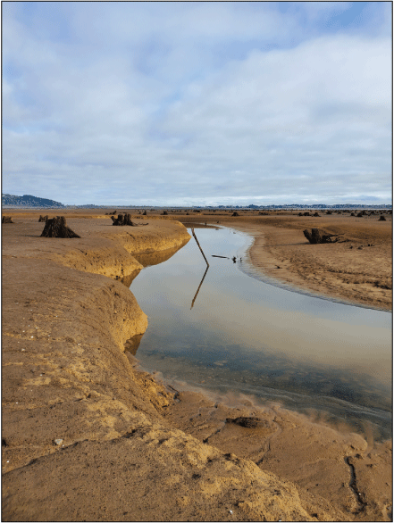
Example of channel banks and wetted channel along the Long Tom River surrounded by undifferentiated reservoir floor within Fern Ridge Lake, Oregon. Tree stumps within the undifferentiated reservoir floor do not typically have exposed roots, indicating a lack of erosion (and some deposition, not shown in photograph). Photograph taken by Mackenzie Keith, U.S. Geological Survey, November 19, 2023.
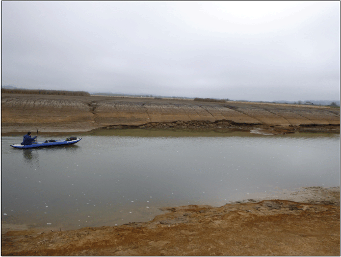
Example of channel banks and wetted channel along Coyote Creek surrounded by undifferentiated reservoir floor within Fern Ridge Lake, Oregon. Banks in this section of Coyote Creek show erosion by calving failures and rilling from dewatering of the reservoir floor. Photograph taken by Mackenzie Keith, U.S. Geological Survey, February 8, 2022.
Bank—Slumping Bank
General description and surface expression or distinguishing feature—Channel banks showing signs of slumping or mass failure are mapped as slumping banks. These landforms include features that show evidence of recent slumping in the 2023 orthophotographs as well as older features. Landforms mapped as slumping banks include discrete curvilinear scarps and transverse cracks within the runout of unconsolidated slumped material; as mapped, slumping bank landforms include both the erosional source and depositional slump areas. In some areas, the curvilinear morphology of a slump failure is still visible along stream banks but is less pronounced than more recent failures by the subsequent deposition of reservoir sediments; although apparently inactive when the 2023 imagery was acquired, these less distinct failures are presumed to represent slumps from previous drawdown events and are mapped as slumping banks. As mapped, slumping banks only occur on a portion of the Long Tom River.
Criteria for linework digitization and landform delineation or elaboration on distinguishing features—Like channel banks, slumping banks are delineated separately from the wetted channels. The slumping banks are distinguished from regular channel banks by evidence of mass failure, such as curvilinear scarps and displaced slump deposit.
Inferred formation processes—Slumping banks occur in channel banks where channel-bed lowering causes mass failure or when saturated banks become dewatered during receding lake levels (for example, also observed at Fall Creek Lake during deep lake-level drawdowns). Though the mechanism of failure observed in Fern Ridge Lake is largely through rotational slump failure, other failure mechanisms can include shallow slides and stream undercutting. Most commonly, this unit within fine sediment sized reservoir floor deposits.
Geomorphic significance in relation to dam operations—In Fern Ridge Lake, slumping banks typically occur along the meandering section of the Long Tom River within relatively fine (sand and mud) reservoir floor deposits, and failure of that sediment into or near the main wetted channel increases the likelihood of transportation.
Basin
General description and surface expression or distinguishing feature—Basins, including backswamps, are areas within the reservoir floor that are topographically lower than surrounding areas. Basins typically are broad with a poorly defined boundary, though some basins may appear narrow due to topographic constrictions. Modern or relict channels can flow into or through some basins.
Criteria for linework digitization and landform delineation or elaboration on distinguishing features—Basins are delineated as broad topographic lows among slightly elevated reservoir floor, commonly occurring adjacent to where tributary or relict channels dissipate. Depending on reservoir levels, basins may be aerially exposed or inundated. Basins are distinguished from relict channel or swale landforms based on their generally broad shape with poorly defined boundary rather than the linear shape of a channel, though water within basins may still have a general direction of flow toward an outlet.
Inferred formation processes—Most basin landforms likely began forming prior to dam construction through natural channel and floodplain processes—for example, as stream channels shifted, built levees, and flooded thereby creating back basins with relatively lower energy areas where finer sediments deposit. The distinction between the basin landform and the relict channel or swale landform is complex as several mapped features of both landform types are likely transitional in formation.
Geomorphic significance in relation to dam operations—As topographically lower landforms within the reservoir floor process domain, basins generally evolve by some fine sediment accumulation during lacustrine conditions.
Cut
General description and surface expression or distinguishing feature—Landforms mapped as cuts are areas where the topography has been affected by the human removal of material). These landforms are topographically lower than adjacent topography and mantled with a thin layer of sediment. Cut landforms commonly form pond or channel-like features at lowered lake levels.
Criteria for linework digitization and landform delineation or elaboration on distinguishing features—Cut landforms are delineated at the top of the slope leading to the bottom of the cut. Cuts may be exposed, partially inundated, or fully inundated. Cut landforms generally have a well-defined boundary and relatively more prominent break in slope as compared with basin landforms.
Inferred formation processes—Created by the removal of substantial amounts of material from the existing landform (for example, as part of construction activities or for aggregate extraction).
Geomorphic significance in relation to dam operations—Depositional, may retain water at low pool, may be re-excavated to maintain function
Distributary Zone
General description and surface expression or distinguishing feature—Distributary zones are broad areas within the reservoir floor that are generally located at distal end of drawdown, tributary, or main wetted channels and display a series of splays, small bars, and (or) small deltaic lobes that are crosscut by erosional channel features.
Criteria for linework digitization and landform delineation or elaboration on distinguishing features—Distributary zones are distinguished from adjacent reservoir floor and main channel landforms by their complex topography of channels and surfaces; the complexity and scale of those landforms prevents detailed mapping of each individual landform. In Fern Ridge Lake, these landforms are commonly found where the downstream end of channels approach and combine with minimum conservation pool levels.
Inferred formation processes—Distributary zones form in low gradient settings where streamflow velocities and sediment transport capacity are reduced as channelized flows enter a relatively lower gradient zone and sediments are deposited. In Fern Ridge Lake, formation of these landforms is likely influenced by reservoir deposition in the lower, downstream portions of the reservoir and in conjunction with pool level.
Geomorphic significance in relation to dam operations—The suite of landforms included within a drawdown distributary zone signifies areas of streamflow expansion and deposition. Seasonal drawdowns for flood control probably serve to mobilize sediment from the upper reservoir areas to the lower reservoir areas through these distributary zones and drawdown channels.
Examples—Figure 4
Drainage Channel
General description and surface expression or distinguishing feature—Drainage channels are channelized landforms that predate dam construction (as verified on pre-dam aerial imagery) and drain saturated areas within wetlands, hillslopes, or higher paleo-floodplains of the reservoir floor. These landforms may have evolved since dam construction to function similar to drawdown channels. Drainage channels may also include human-made channels that were likely intended to drain or re-route water off of the floodplain (distinguishable from cuts because they are functioning as channels).
Criteria for linework digitization and landform delineation or elaboration on distinguishing features—Drainage channels are delineated between the tops of the banks on either side of the channel, where the channel is 1 m or wider, and include both wetted and non-wetted surfaces within the channel. The downstream end of drainage channels may connect to a basin or main channel. The heads of drainage channels are initiated within the reservoir (including within wetlands). In some places, drainage channels may occupy a relict channel or swale landform and are distinguished from those landforms based on their function.
Inferred formation processes—Drainage channels may form naturally from the concentrated flow of water from a saturated source or by human actions to route water to or from a specific location (such as along roads, through fields, or from a pond or other wet area).
Geomorphic significance in relation to dam operations—At low pool levels, drainage channels may be dry or wetted and likely function similar to drawdown channels or tributary channels (described below), transporting sediment and channeling local streamflow from ephemeral or perennial water sources within the reservoir. Drainage channels may be incised into pre-dam sediments where they have functioned as drainage channels over multiple years of lake lowering and rising and have become established. Conversely, shallow and surficial drainage channels can develop in reservoir floor deposits or wetland areas and shift annually without the ability to become an established persistent feature in the reservoir.
Examples—Figures 4, 8, and 12–14
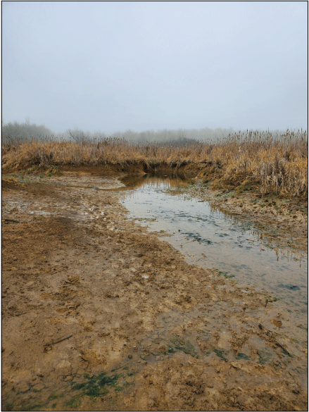
Example of a drainage channel (nested within a relict channel) that is draining and head-cutting into an area mapped as wetlands within Fern Ridge Lake, Oregon. Photograph taken by Mackenzie Keith, U.S. Geological Survey, February 9, 2022.
Drawdown Channel
General description and surface expression or distinguishing feature—Drawdown channels are channels that originate predominantly from head cuts through the reservoir floor or reservoir hillslope and do not extend beyond the perimeter of Fern Ridge Lake as do tributaries. Drawdown channels typically drain to landforms mapped as main channels. Unlike Fall Creek Lake, drawdown channels do not regularly evolve into small drawdown distributary zones.
Criteria for linework digitization and landform delineation or elaboration on distinguishing features—Drawdown channels are delineated similarly to drainage channels, where the width of the mapped landform between the tops of banks exceeds 1 m. Where channels do not show a clear edge in orthophotograph, drawdown channel landforms were delineated based on the clearest break in slope in a DSM-derived slope model (0.17 m resolution). Included in this mapping category are drawdown channels that appear to be actively conveying water and sediment (as indicated by sharp, distinct break between the reservoir floor and channel indicating recent erosion) and older drawdown channels, which were likely formed during previous drawdowns but now have rounded, smooth banks that lack signs of recent erosion. Some drawdown channels also show signs of headward erosion that formed deep, steep-walled channels (gullies) with sharp knickpoints whereas other drawdown channels begin as gently sloping features that gradually deepen in the downstream direction. The reservoir floor commonly contains networks of small unmapped drawdown channels, particularly within the lower paleo-floodplain.
Inferred formation processes—Drawdown channels are drainage landforms that likely form in response to seasonal drawdowns of the reservoir for flood control. As lake levels are lowered, water draining from the low gradient floor likely concentrates within these channels, increasing local capacity to mobilize and transport fine-grained sediment thereby carving the channel. Once the channels incise into reservoir floor (lacustrine deposits or pre-dam strata), over-steepening and bank failure is the primary mechanism for widening of those channels (Morris and Fan, 1998, p. 15.17), similar to landforms at Fall Creek Lake. Over time, these landforms can evolve head cutting through knickpoint upstream migration (retrogressive erosion) or increases in local slope that increase the efficiency of streamflow and sediment transport through the landform.
Geomorphic significance in relation to dam operations—As mapped from drawdown imagery, many drawdown channels are dry at low pool but probably convey sediment when lake levels are being lowered or during storm events when exposed above the reservoir water surface. Topographically, most drawdown channels are incised into reservoir floor deposits and their bed elevations are higher than nearby pre-impoundment surfaces in net-depositional portions of the reservoir.
Fill and Infrastructure
General description and surface expression or distinguishing feature—Landforms and features mapped as fill and infrastructure are areas where the reservoir topography has been purposely changed since the late 1800s, in some cases by the addition of material (fill) and are commonly associated with pre-dam and modern infrastructure (for example, roads). Many of these landforms within the reservoir are now mantled with lacustrine sediment, but the underlying morphology of the landform itself is still clearly visible (for example, road embankment). Fill and infrastructure landforms may include piles of blocky material (mostly in the lower reservoir, where piles are probably associated with dam construction), filled road grades, pre-impoundment pond embankments, post-dam piers and boat ramps, modern roads and railways, and shoreline stabilization (such as revetment).
Criteria for linework digitization and landform delineation or elaboration on distinguishing features—Where fill and infrastructure are locally elevated topographic landforms (such as roads grades), they are delineated along the base of the slope on either side of the feature. No effort was made to distinguish between fill and infrastructure landforms within the reservoir that are connected and made of similar material (for example, a road leading to an old foundation). Infrastructure such as piers, boat ramps, and revetment are delineated along the edge of the material that comprises the landform or feature.
Inferred formation processes—Fill and infrastructure landforms and features were created by humans primarily since the late 1800s.
Geomorphic significance in relation to dam operations—Fill and infrastructure are typically stable features elevated above surrounding reservoir floor or other process domains. During lake-level lowering and raising for flood control, fill and infrastructure could affect local hydraulic patterns (for example, road fill could act as levee-like barrier to flow between different parts of the reservoir).
Hillslope
General description and surface expression or distinguishing feature—The reservoir hillslope landform mapping unit consists of steep areas of the reservoir margins that typically extend from the reservoir floor upward to the reservoir margins near elevation 373.5 ft coinciding with maximum conservation pool.
Criteria for linework digitization and landform delineation or elaboration on distinguishing features—The reservoir hillslope landform consists of broad, steep slopes (greater than about 5 degrees) forming the reservoir walls that tend to be relatively steeper than shoreline areas. These steep areas may show wave-cut terracettes indicative of net erosion, but in lower gradient areas may have some sediment accumulation. Reservoir hillslopes are primarily delineated by breaks in slope or a change in substrate type or color. The lower boundary for reservoir hillslope is commonly defined by a break in slope with the reservoir floor. The reservoir hillslope landforms are exclusively found within the reservoir hillslope process domain.
Inferred formation processes—The main reservoir hillslope formation pre-dates dam construction. The reservoir slope represents areas unlikely to accumulate sediment, due to the migration of sediment downslope to the reservoir floor, or subject to net erosion due to wave action resulting from changes in reservoir lake levels. These landforms are typically net erosional, as sometimes evidenced by wave-cutting visible in the orthophotographs. Fern Ridge Lake shows occasional wave-cut terraces on the reservoir slope common with fluctuating lake levels. In general, the shoreline serves as the perimeter of the reservoir during higher pool elevations. Shoreline areas are unlikely to accumulate sediment and are prone to net erosion where lacking stabilizing vegetation, revetment, or naturally geologically stable substrates. due to wave action resulting from changes in reservoir lake levels. Wave attack through wind or recreational driven waves at relatively higher pool levels have resulted in local erosion and shoreline retreat in some areas. Steepening of some locations results from the waves has occurred through ‘chronic’ erosion of surfaces or through mass wasting (collapse/calving/tree fall).
Geomorphic significance in relation to dam operations— The combination of steep slopes and adjacent lake perimeter makes hillslope landforms susceptible to wind and boat driven wave attack. At higher pool levels, waves can affect shoreline areas, particularly steeper areas with longer fetch, lacking vegetation, or in heavily utilized recreation areas (or some combination). At lower pool levels, shoreline areas (relative to maximum pool) are exposed to wind and rain that may cause erosion. Evidence of shoreline failure, mass wasting and tree fall, could be related to some combination of dewatering during lowered pool levels, saturated conditions during winter rain, and wind affecting the bank (directly or indirectly by tipping trees). Hillslopes may be sources of coarse- and fine-grained sediment to the reservoir floor and channels as lake levels are lowered and wave energy interacts with ground surface. However, there is likely limited transport of this locally derived material beyond the reservoir floor through the regulating outlets to downstream reaches unless the reservoir hillslope is adjacent to the main channels, tributary channels, or drawdown channels that have sufficient transport capacity.
Examples—Figures 4, 9, 12, and 14
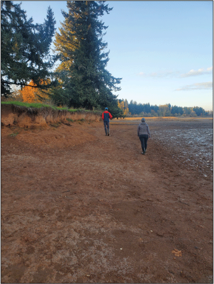
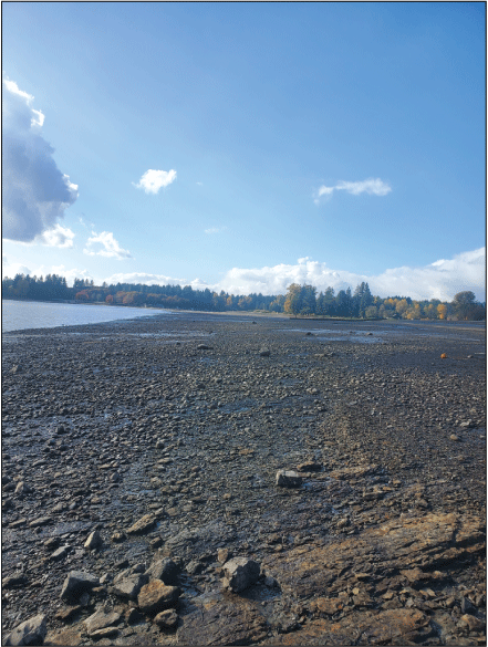
Example of hillslope landform with relatively steep, near vertical eroding shoreline towards the left of the photograph adjacent to modestly steep hillslope (where people are walking) which is adjacent to lower gradient reservoir floor (saturated sediment towards the right of the photograph) within Fern Ridge Lake, Oregon. Photograph taken by Mackenzie Keith, U.S. Geological Survey, November 7, 2023.
Levee
General description and surface expression or distinguishing feature—Levees, as mapped in Fern Ridge Lake, include natural embankments or aprons that form elevated surfaces adjacent to main and relict channels. Levees are low gradient topographic landforms that may be covered in fine sediment or vegetation. Generally, these landforms have steeper slopes between crest and channel and lower sloping surface away from the crest and channel. Artificial, human-made levees would be mapped as the ‘fill and infrastructure’ landform unit where present.
Criteria for linework digitization and landform delineation or elaboration on distinguishing features—Levee landforms are delineated based on topographic expression and variations in color and textures that bound present day channels and distinguish levees from the surrounding reservoir floor. Levee landforms associated with historical channel systems may retain topographic expression in some areas; however, these landforms tend to be even more muted in DSM and orthophotographs and were therefore not mapped (commonly lumped with other reservoir floor or swale/relict channel landforms).
Inferred formation processes—Formation is primarily by naturally occurring overbank inundation and fine sediment deposition. In some cases, mapped levees were likely formed before construction of Fern Ridge Dam (such as along the meandering section of the Long Tom River). Levees mapped along distributary zones near the low pool may be continuing to evolve where channel processes dominate, and flashy flows result in overbank deposition. These landforms are likely subject to additional sedimentation during reservoir refill when resuspension of fine sediment occurs.
Geomorphic significance in relation to dam operations—These landforms mainly are a zone of accumulation during low pool and largely stable once established, but unconsolidated levee sediments could be cut through by drainage channels or rills. Likely most levees along main wetted channels and relict channels formed prior to dam construction, though it is possible additional formation could occur during flood events at low pool levels.
Reservoir Floor, Undifferentiated
General description and surface expression or distinguishing feature—The undifferentiated reservoir floor at Fern Ridge Lake is the main floor of the reservoir extending between the reservoir hillslope and main reservoir channels. It is generally downslope of the reservoir hillslope process domain, relatively flat, and would be fully inundated by water at maximum pool (373.5 ft). Reservoir floor subdivision into pelagic (deeply inundated at full pool) or littoral (adjacent to the reservoir boundary and shallowly inundated at full pool) as was done for Fall Creek Lake (Keith and Stratton Garvin, 2021) was not applied to Fern Ridge Lake as the transition from littoral to pelagic is gradual and poorly defined. Therefore, all reservoir floor surfaces are mapped as undifferentiated floor, which is most commonly covered with sand and finer sediment and lacks distinct topographic features.
Criteria for linework digitization and landform delineation or elaboration on distinguishing features—The reservoir floor generally has a low gradient (typically less than about 2 degrees) and a smooth appearance in DSM (lack of topographic roughness) and orthophotographs (lack of color variation) related to sand and finer-grain sediment accumulation. The reservoir floor within this mapping framework is bound by reservoir hillslopes or wetlands (or other), that separate the mapped floor and from mapping boundary at reservoir maximum pool. Reservoir floor deposit thickness varies throughout the reservoir depending on elevation, proximity to minimum pool, and influence of different tributary channels with unique sediment transport conditions. In situ tree stumps that pre-date dam construction are still visible and provide evidence of almost no to modest deposition, particularly where the basal root-flare is still visible. Thicker sediment deposits include flat, broad areas that more deeply bury tree stumps. Following reservoir dewatering, a mud-crack pattern on the reservoir floor is visible in some locations within the orthophotographs.
Inferred formation processes—Much of the reservoir consists of former wetlands, floodplain, or low terraces within the Fern Ridge Lake footprint. After impoundment by Fern Ridge Dam, lacustrine sedimentation at higher pool levels or overbank inundation of these areas during lower lake levels resulted in low gradient surface covered in finer sediments. The undifferentiated reservoir floor appears to be (1) net depositional, (2) deeply inundated frequently enough to preclude significant macrophyte growth, and (3) primarily influenced by suspended-sediment deposition. Undifferentiated floor at Fern Ridge, like Fall Creek, generally has a smooth surface appearance lacking bedforms, suggesting that deposition is primarily due to suspended-sediment deposition, which tends to mantle pre-existing topography. Reservoir floor deposits appear to mantle pre-dam terraces and floodplains of the streams entering the reservoir.
Geomorphic significance in relation to dam operations—During seasonal flood-control operations at Fern Ridge Lake, the undifferentiated reservoir floor predominantly is a depositional zone. The smooth, low-gradient surface indicates limited influenced by major erosional processes except drawdown channels or drainages channels (separately mapped) or smaller rills that show evidence of incision through reservoir deposits and sometimes even deeper through pre-dam topography. The reservoir floor deposit could be a potential source of sediment to be remobilized. However, at the time of mapping, the sediment regimes for the undifferentiated reservoir floor are primarily depositional or neutral as evidenced by the long-term annual lake-level fluctuations have remained relatively consistent and inferred limited sediment deposition in areas exposed at low pool conditions, respectively.
Relict Channel or Swale
General description and surface expression or distinguishing feature—Relict channel or swale landforms are curvilinear, topographically depressed landforms typically within the reservoir floor that pre-date dam construction and were likely at one point a channel or feature of concentrated streamflow but have undergone sedimentation from fluvial and lacustrine processes after the reservoir was created.
Criteria for linework digitization and landform delineation or elaboration on distinguishing features—Relict channel or swale landforms are mapped between the break in slope on either side of the feature. These landforms are typically distinctly curvilinear in shape and may parallel modern channels and (or) connect with channels and basins across the reservoir floor. These landforms are commonly crosscut by more recent processes and sometimes reoccupied by modern flowing channels. Where uncertain, landforms observed in the orthophotographs were compared with historical imagery from 1939 to confirm pre-dam establishment.
Inferred formation processes—Relict channels or swales were likely formed as historical stream channels or areas of concentrated flow that have since been cut off from active flow processes, possibly due to channel abandonment during river migration or other disconnection from a water source. Over time, these landforms soften in relief as they become places of fine sediment accumulation during overbank flows during pre-dam construction and lacustrine deposition after the reservoir was established.
Geomorphic significance in relation to dam operations—At low pool levels, relict channels or swales may be dry or inundated with water flowing between landforms across the reservoir floor. Drainage and drawdown channels may also flow along the path of a relict channel or swale. During reservoir water level fluctuations, relict channels or swales may be areas of focused inundation or even water flow until fully inundated or drained. At high pool, these landforms are subject to continued fine sedimentation due to lacustrine deposition.
Examples—Figures 4, 8, 10, 12, 13, and 15
Example of an abandoned oxbow with standing water mapped as “relict channel or swale” landform within the reservoir floor process domain along the Long Tom River within Fern Ridge Lake, Oregon. Photograph by Mackenzie Keith, U.S. Geological Survey, December 14, 2022.
Tributary Channel
General description and surface expression or distinguishing feature—Tributary channels are small channels that typically originate beyond the reservoir perimeter and drain directly into either a main wetted channel or the low reservoir pool. In contrast to the main channel landforms, tributary channels are mapped from the top of banks, encompassing channel banks, wetted or dry channel bed, and any adjacent channel margins.
Criteria for linework digitization and landform delineation or elaboration on distinguishing features—Tributary channels were delineated based on a channel width, where channels wider than 1 m were mapped. The upstream end of tributary channels is mapped so that they truncate near the outer reservoir boundary (elevation 373.5 ft). Tributary channels originate near or outside the reservoir mapping boundary, sometimes flowing through wetlands, and are distinct from drawdown channel landforms, which solely originate within the reservoir boundaries from drawdown processes.
Inferred formation processes—In the Fern Ridge Lake, tributary landforms were originally formed by fluvial processes and continue to be maintained by fluvial processes. The general locations of these landforms were established prior to dam construction and may not have changed substantially since dam construction. Because the smaller tributaries tend to be located near the reservoir perimeter (and, by extension, higher in elevation), the upper reaches are exposed during both normal operating drawdowns and full-pool drawdowns. This probably reduces the amount of sediment deposited and helps the tributaries evacuate annual deposits, maintaining them in their pre-impoundment location.
Geomorphic significance in relation to dam operations—Tributaries likely play an important role in the transport of water and sediment from distal reservoir hillslope and floor regions of the Fern Ridge Lake to the main channel. During low pool, the exposed channels can flow freely, and many have changing landforms similar to those mapped in the main channel, although they may be too small to be mapped within this dataset.
Residual Pool
General description and surface expression or distinguishing feature—The residual pool at the time of the survey; during the time of aerial photograph acquisition the lake level was at 352.9 ft (NGVD 1929 at the USGS gage 14168000 Fern Ridge Lake near Elmira, Oregon; U.S. Geological Survey, 2024). The perimeter is indistinct in orthophotographs; mapped landforms may extend beyond and into the pool beyond where the DSM water delineation was placed (related to uncertainty of elevations creation of the DSM; see Schwid and others [2025] for details).
Criteria for linework digitization and landform delineation or elaboration on distinguishing features—The residual pool is not directly mapped but defined by the boundaries that were delineated of adjacent landforms.
Inferred formation processes—The residual, low-pool level is largely controlled by dam operations; however, sedimentation since dam construction to this depositional zone has also likely affected the location of the pool, particularly along the perimeter of low pool.
Geomorphic significance in relation to dam operations—The residual pool is primarily a depositional zone, though it is likely some channel connecting to low level outlets helps to maintain a thalweg.
Wetlands
General description and surface expression or distinguishing feature—Mapped wetlands as landforms are distinguished by a continuous cover of vegetation ranging from herbaceous to woody (such as reed canary grass, blackberries, bulrush, or mature trees as observed in the field and not distinguished from orthophotographs). The wetland landform class is typically low gradient although locally steep areas likely present; no distinct topographic features are visible in the DSM which is likely due to the dense vegetation that was modeled during photogrammetric processing. Mapped wetlands are primarily found along shallow margins of reservoir area, especially where tributaries enter the reservoir and (or) in coves and bays; densest along the shoreline and thins as it extends from shoreline toward center of reservoir; includes stand-alone bulrush clumps that grow just beyond the margin of the dense vegetation. This mapping unit does not represent any official, regulatory, or legal definition of a wetland.
Criteria for linework digitization and landform delineation or elaboration on distinguishing features—The dominant criteria for mapping the wetlands landform unit were dense vegetation on channel margins and on higher elevation surfaces within the lake, such as Gibson Island, many of which are fully or partially inundated when the reservoir is fully. The wetlands landform also includes non-vegetated areas and pooled water within the wetlands process domain.
Inferred formation processes—Some of the wetland areas were likely formed in the low gradient, saturated soils near tributaries entering the wider valley prior to establishment of Fern Ridge Lake whereas other areas were likely formed through extended periods of elevated lake levels imposed by reservoir operations.
Geomorphic significance in relation to dam operations—Areas mapped as wetland landforms for the Fern Ridge mapping framework are typically low gradient areas along the perimeter of the reservoir, especially where tributaries enter the reservoir area. During high-pool conditions, wetlands could accumulate some modest amounts fine sediment where inundated or where intermittent flooding occurs. At low-pool conditions, saturated wetland areas may dewater more slowly than bare areas and drain to the main channel or reservoir floor process domains. During this time, wetlands are likely a limited source of sediment to the reservoir except where drainage or drawdown channels may be actively head cutting into these landforms. Overall, wetlands tend to be fairly stable landforms on the landscape given their dense vegetation cover.
Wetted Channel
General description and surface expression or distinguishing feature—Wetted channels mapped in Fern Ridge Lake include the main wetted channel areas of Amazon Creek, the mainstem, Middle, and West Coyote Creeks, multiple arms of the Long Tom River, Hannavan Creek, and Inman Creek during low-pool conditions, but not other smaller, permanent tributaries. Landform delineation is defined by the area inundated by water at the time of complete reservoir drawdown as observed in orthophotographs. This mapping unit includes the main wetted channel bed surface and forms a part of the main channel process domain.
Criteria for linework digitization and landform delineation or elaboration on distinguishing features—The wetted channel is delineated based on the intersection of surface water and dry land along the edges of major tributaries to Fern Ridge Lake as visible in the orthophotographs. Landforms smaller than the minimum mapping unit that are adjacent to or within the wetted channel may be lumped with the wetted channel (for example, small bars).
Inferred formation processes—In Fern Ridge Lake, the general position of wetted channels was likely established prior to dam construction. The overall channel planform does not appear to have changed substantially in the about 80 years following dam construction (with the exception of Amazon Creek); however, areas of bank erosion, channel migration, and meander cutoffs have been identified. Several of the channels within the reservoir have been straightened or modified prior to dam construction (for example, branches of the Coyote Creeks). Amazon Creek was diverted into the reservoir in 1954–59. Field observations also suggest minimal deposition in the upper reaches most of the main channels: Long Tom River braid, Hannavan Creek, Amazon Creek, and Inman Creek flow across hardpan clay surfaces in the upper reservoir, but the presence of finer sediment increases towards the dam. The position and geometry of the wetted channel is likely maintained with a combination underlying geology, relatively low coarse sediment supply (O’Connor and others, 2014, 2021). Additionally, lowering the pool annually, helps to ‘maintain’ the upper reaches. Lower reaches are (lower gradient, lower streamflow, subject to backwater, and more time inundated) are prone to more in-channel deposition.
Geomorphic significance in relation to dam operations—At Fern Ridge Lake, the mapped wetted channel landforms are the primary conduits of streamflow and sediment at low pool levels. The relative size (compared with smaller mapped tributaries) and source area heading beyond the reservoir boundary (unlike relict or drainage channels that source within the reservoir) increase the potential for greater streamflows and upstream sediment supply to the reservoir. Within the reservoir, the main wetted channels are relatively low gradient; however, the channel bed in several segments (particularly in the upper reservoir) flows across a relatively cohesive and resistant hard-pan clay (likely weathering bedrock) suggesting, at least during low pool conditions, transport capacity exceeds sediment supply in these segments. During high pool conditions coinciding with fewer rain-driven storms and lower streamflows, sediment transporting flows and supply to the reservoir, and more so the lower reservoir, are probably low and backwater conditions would shift the main locus of deposition farther upstream (upper reservoir or beyond).
Other
There are a few landforms or features within Fern Ridge Lake that do not fit the descriptions of other landform mapping categories. As opposed to creating additional mapping units, those landforms and features are grouped into the unclassified category “other.” These landforms and features include forested areas within the mapped region and ODFW-maintained wetlands, ponds, and portions of infrastructure along the reservoir margin of the reservoir. Lands managed by ODFW land did not automatically result in a landform level classification as other.
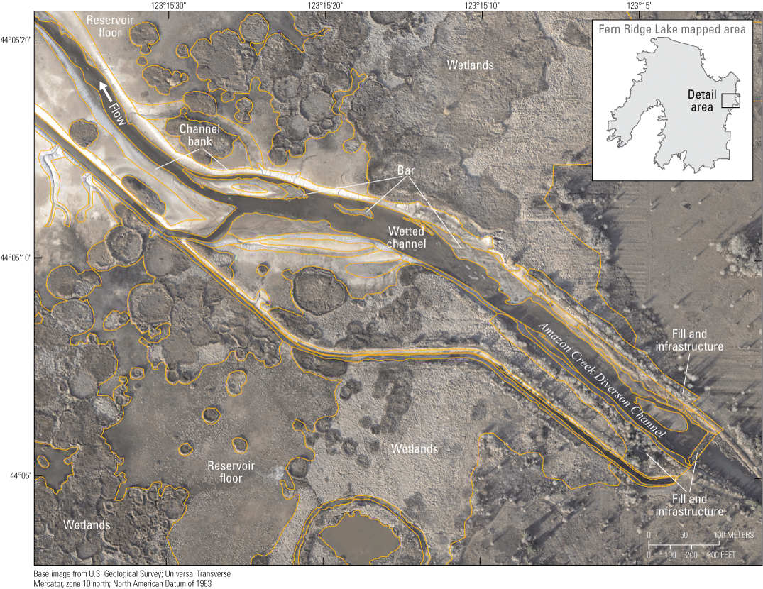
Geomorphic mapping (Bervid and Keith, 2025) over high-resolution orthophotographs (Schwid and others, 2025) of Fern Ridge Lake, Oregon, showing multiple mapped landforms near the Amazon Creek Diversion Channel: bars, channel bank, wetted channel, fill and infrastructure, reservoir floor, and wetlands.
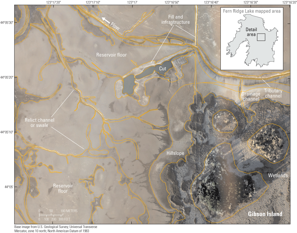
Geomorphic mapping (Bervid and Keith, 2025) over high-resolution orthophotographs (Schwid and others, 2025) of Fern Ridge Lake, Oregon, showing multiple mapped landforms near Gibson Island: hillslope, relict channel or swale, tributary channel, fill and infrastructure, reservoir floor, and wetlands.
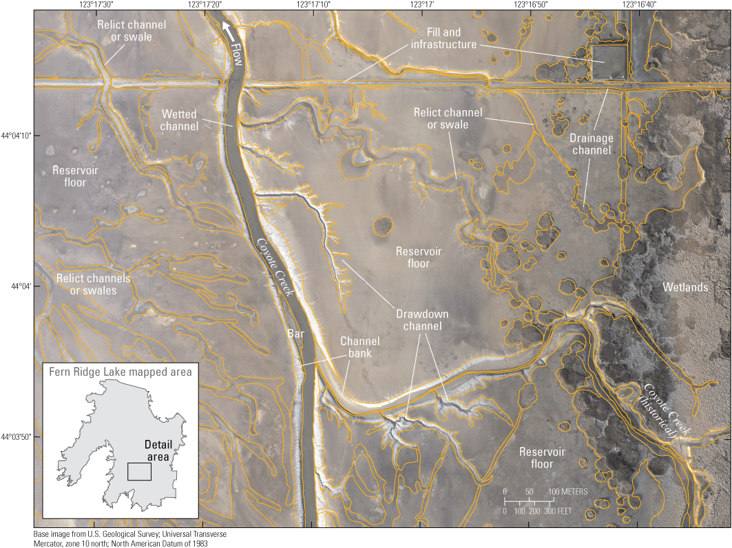
Geomorphic mapping (Bervid and Keith, 2025) over high-resolution orthophotographs (Schwid and others, 2025) of Fern Ridge Lake, Oregon, showing multiple mapped landforms near Coyote Creek: bar, channel bank, relict channel or swale, wetted channel, drawdown channel, drainage channel, fill and infrastructure, reservoir floor, and wetlands.

Geomorphic mapping (Bervid and Keith, 2025) over high-resolution orthophotographs (Schwid and others, 2025) of Fern Ridge Lake, Oregon, showing multiple mapped landforms near Fern Ridge Dam: hillslope, drainage channel, tributary channel, fill and infrastructure, reservoir floor, wetlands, and unmapped pool.
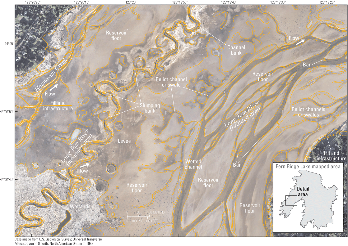
Geomorphic mapping (Bervid and Keith, 2025) over high-resolution orthophotographs (Schwid and others, 2025) of Fern Ridge Lake, Oregon, showing multiple mapped landforms Hannavan Creek and the meander and braided arms of the Long Tom River: wetted channel, channel banks, slumping banks, bar, levee, relict channel or swale, fill and infrastructure, reservoir floor, and wetlands.
Cover Categories
Cover categories (table 2; fig. 16) were assigned to each landform and included four subcategories for substrate, as well as categories for infrastructure, water, and vegetation. Substrates are generalized by grainsize or material of a landform, as identified in orthophotograph (resolution of 5–10 centimeters [cm]/pixel). Substrate categories are generalized, not systematically field-verified, and based almost solely on appearance (texture and color) in orthophotograph. Field observations were useful for verifying different mapped substrate categories.
Cover categories assigned to each of the mapped landforms for Fern Ridge Lake, Oregon.
Bedrock
Bedrock (table 2; figs. 16, 17) may have jagged or blocky appearance in both DSMs and orthophotographs, contrasting with the smooth texture of alluvial landforms. Bedrock at Fern Ridge Lake is dominantly sedimentary rock and generally appears lighter in color and typically has a coarser texture than sand and finer deposits of the reservoir floor. Bedrock at Fern Ridge Lake varies from much of the bedrock visible at Fall Creek Lake that typically had jagged or blocky appearance in both DSMs and orthophotographs and was similar in tone to darker-colored gravel deposits. At Fern Ridge Lake, weathered gravels are present and eroding from local sedimentary bedrock, so some areas mapped as bedrock cover may be covered in a veneer of gravel.
Thin veneer of gravel mantles areas mapped as “bedrock” cover within Fern Ridge Lake, Oregon, and reflects weathering of the underlying bedrock. Photograph taken near Richardson Park by Mackenzie Keith, U.S., Geological Survey, November 7, 2023.
Gravel
Gravel cover (table 2; fig. 16) areas consist of patches of coarse sediment where clasts are predominantly coarser than sand. Typically, these areas are confined to the main channel within the reservoir and have a lighter grayish and rougher textured appearance than finer (brown and smooth surfaces) sediments. In areas where a veneer of gravel mantles another substrate category, the landform is mapped as the underlying substrate unless gravel cover is more than 50 percent by area.
Sand and (or) Mud
The sand and (or) mud cover category (table 2; fig. 16) consists of patches of fine-grained sediment that are predominantly comprised of sand, silt, and mud with overall grain size generally less than 2 millimeters (mm). Sand and (or) mud substrate covers most low relief landforms in the lower reservoir and has a slightly browner color and smoother appearance than the coarser gravel (greater than 2 mm) substrate. Some areas may also be covered in a veneer of gravel.
Variable and (or) Unknown
The variable and (or) unknown cover classification (table 2; fig. 16) is used for areas where the substrate is identifiable but too spatially variable (less than about 10 m2 by patch) to map as separate polygons and for areas where the substrate is unknown.
Infrastructure
Cover labeled as infrastructure (table 2; fig. 16) includes features such as pre-dam roads or home foundations developed between the later 1800s and the construction of Fern Ridge Dam, as well as presently maintained boat ramps and Fern Ridge Dam. Several of these features are mantled by sediment so they are sometimes mapped from a combination of orthophotograph and DSM and are delineated more on the shape or morphology of the landform. If sediment covering infrastructure is sufficiently thick that the underlying landform is identifiable but not clearly defined because of sediment deposition, then the landform is mapped as the appropriate sediment category for the overlying sediment (most commonly sand and [or] mud).
Water
The water cover category (table 2; fig. 16) indicates areas of inundation at the time or orthophotograph collection. Channel-bed substrates are sometimes visible below the water surfaces within the wetted channel landform; although visible, cover is still mapped as water. Throughout much of the reservoir, saturated sediment or ponded water with shallow inundation may be mapped as water or as the underlying substrate depending on which class was more distinguishable in the orthoimagery.
Vegetation
Vegetation (table 2; fig. 16) covers a substantial portion of the mapping area. This cover category most commonly coincides with higher elevation reservoir surfaces that are subject to modest inundation in terms of number of days inundated or depth of inundation. Shallow water levels across much of the reservoir at high pool levels and broad exposed areas at low pool permit the growth of emergent macrophytes and herbaceous vegetation (for example, reed canary grass [Phalaris arundinacea], bulrush [Scirpus spp.]) across the reservoir floor. Higher elevation surfaces that are rarely inundated and not inundated by lake level operation may also support brushy and woody vegetation. ODFW estimates that about 2,500 acres of emergent vegetation is present along the mostly southern and eastern edges of the reservoir, dominated by non-native, invasive species such as reed canary grass but also including important native plants such as hardstem bulrush (Schoenoplectus acutus), cattail (Typha latifolia), wapato (Sagitaria latifolia), smartweed (for example, Persicaria lapathifolia), and other native wetland plants (Oregon Department of Fish and Wildlife, 2020). Vegetation is not broken down into sub-units. Classifying vegetation types is outside the scope of this mapping effort but could be implemented following established protocols (for example, Keith and others, 2022) in the future from the same datasets underlying the geomorphic mapping (Schwid and others, 2025).
Summary
Geomorphic maps of Fern Ridge Lake, Oregon, were produced to show reservoir conditions, with the reservoir extending over an area of about 30 square kilometers. The mapping was completed to inform U.S. Army Corps of Engineers (USACE) cultural resources management but is also useful for informing dam, sediment, ecological, and natural resource management issues. The mapping focuses on the USACE reservoir-management area between minimum and maximum pool levels that is exposed each year during seasonal flood-control operations and consists of three categories:
-
• Process domains are applied to groupings of landforms encompassing large regions of the reservoir with broadly similar formational or functional processes. This study identified five process domains including main channel, reservoir hillslope, reservoir floor, and wetlands. The fifth process domain, ‘other,’ encompassed multiple landforms that did not fit into another process domain.
-
• Landforms within the Fern Ridge Lake primarily consist of features interpreted to have been formed predominantly by reservoir processes and human activities, though pre-dam geomorphic processes and surfaces provide an important influence on the evolution of the reservoir landforms after dam construction. Eighteen landform categories were mapped for Fern Ridge Lake including several types of channel features, two types of banks, wetlands, reservoir floor and hillslopes.
-
• Cover was assigned to all landforms and was classified according to seven cover types, including multiple substrate categories generalized by grainsize for landforms, infrastructure, water, or vegetation.
This report summarizes delineation criteria, hypothesized formation processes inferred from remote-sensing, field observations, previous studies, and conditions during seasonal flood-control drawdown operations. The digital maps (Bervid and Keith, 2025) are publicly available and can be accessed through ScienceBase (https://www.sciencebase.gov/catalog/; https://doi.org/10.5066/P13MHC5P).
References Cited
Bervid and Keith, 2025, Geomorphic Mapping of Fern Ridge Lake, Oregon, 2023: U.S. Geological Survey Data Release, https://doi.org/10.5066/P13MHC5P.
Keith, M.K., and Mangano, J.F., 2020, Structure-from-motion datasets of Fall Creek Lake, Oregon, acquired during annual drawdown to streambed November 2016: U.S. Geological Survey Data Release, https://doi.org/10.5066/P9AYWU8Z.
Keith, M.K., and Stratton Garvin, L.E., 2019, Linking sedimentation and erosion patterns with reservoir morphology and dam operations during streambed drawdowns in a flood-control reservoir in the Oregon Cascades: Proceeding of SEDHYD-2021, Sedimentation and Hydrologic Modeling Conference, June 24–28, Reno, Nevada, 12 p.
Keith, M.K., and Stratton Garvin, L.E., 2021, Geomorphic mapping of Fall Creek Lake, Oregon, 2016: U.S. Geological Survey Data Release, accessed July 14, 2023, at https://doi.org/10.5066/P9YZSJJJ.
Keith, M.K., Wallick, J.R., Flitcroft, R.L., Kock, T.J., Brown, L.A., Miller, R., Hagar, J.C., Guillozet, K., and Jones, K.L., 2022, Monitoring framework to evaluate effectiveness of aquatic and floodplain habitat restoration activities for native fish along the Willamette River, northwestern Oregon: U.S. Geological Survey Open-File Report 2022–1037, 116 p., accessed September 26, 2024, at https://doi.org/10.3133/ofr20221037.
Keith, M.K., Wallick, J.R., Schenk, L.N., Stratton Garvin, L.E., Gordon, G.W., and Bragg, H.M., 2024, Reservoir evolution, downstream sediment transport, downstream channel change, and synthesis of geomorphic responses of Fall Creek and Middle Fork Willamette River to water years 2012–18 streambed drawdowns at Fall Creek Lake, Oregon: U.S. Geological Survey Scientific Investigations Report 2023–5135, 155 p., https://doi.org/10.3133/sir20235135.
O’Connor, J.E., Mangano, J.F., Anderson, S.W., Wallick, J.R., Jones, K.L., and Keith, M.K., 2014, Geologic and physiographic controls on bed‐material yield, transport, and channel morphology for alluvial and bedrock rivers, western Oregon: Geological Society of America Bulletin, v. 126, no. 3–4, p. 377–397, at https://doi.org/10.1130/B30831.1.
O’Connor, J.E., Mangano, J.F., Wise, D.R., and Roering, J.R., 2021, Eroding Cascadia—Sediment and solute transport and landscape denudation in western Oregon and northwestern California: Geological Society of America Bulletin, v. 133, no. 9–10, p. 1851–1874, at https://doi.org/10.1130/B35710.1.
Oregon Department of Fish and Wildlife, 2020, Fern Ridge Wildlife Area Management Plan, March 2020: Oregon Department of Fish and Wildlife, Salem, Oregon, 48 p., accessed January 16, 2025, at https://www.dfw.state.or.us/wildlife/management_plans/wildlife_areas/docs/FRWA%20Management%20Plan%202020.pdf.
Schwid, M.F., Keith, M.K., and Overstreet, B.T., 2025, Structure-from-motion datasets of Fern Ridge Lake, Oregon, during annual low pool January and February 2023: U.S. Geological Survey data release, https://doi.org/10.5066/P1Q5K657.
U.S. Geological Survey, 2024, USGS 14168000 FERN RIDGE LAKE NEAR ELMIRA, OR: U.S. Geological Survey, National Stream Information System (NWIS) online database, accessed March 26, 2025, at https://waterdata.usgs.gov/nwis/uv?site_no=14168000&legacy=1.
Datums
Vertical coordinate information is referenced to the National Geodetic Vertical Datum of 1929 (NGVD 29).
Horizontal coordinate information is referenced to the North American Datum of 1983 (NAD 83).
Elevation, as used in this report, refers to distance above the vertical datum.
For information about the research in this report, contact
Director, Oregon Water Science Center
U.S. Geological Survey
601 SW 2nd Avenue, Suite 1950
Portland, OR 97204
https://www.usgs.gov/centers/or-water
Manuscript approved on August 7, 2025
Publishing support provided by the U.S. Geological Survey
Science Publishing Network, Tacoma Publishing Service Center
Edited by Vanessa Ball
Illustration support by JoJo Mangano
Illustration and layout by Luis Menoyo
Disclaimers
Any use of trade, firm, or product names is for descriptive purposes only and does not imply endorsement by the U.S. Government.
Although this information product, for the most part, is in the public domain, it also may contain copyrighted materials as noted in the text. Permission to reproduce copyrighted items must be secured from the copyright owner.
Suggested Citation
Keith, M.K., and Bervid, H.D., 2025, Framework developed for geomorphic mapping of Fern Ridge Lake, Oregon, 2023: U.S. Geological Survey Data Report 1215, 33 p., https://doi.org/10.3133/dr1215.
ISSN: 2771-9448 (online)
Study Area
| Publication type | Report |
|---|---|
| Publication Subtype | USGS Numbered Series |
| Title | Framework developed for geomorphic mapping of Fern Ridge Lake, Oregon, 2023 |
| Series title | Data Report |
| Series number | 1215 |
| DOI | 10.3133/dr1215 |
| Publication Date | September 04, 2025 |
| Year Published | 2025 |
| Language | English |
| Publisher | U.S. Geological Survey |
| Publisher location | Reston, VA |
| Contributing office(s) | Oregon Water Science Center |
| Description | Report: viii, 33 p.; Data Release |
| Country | United States |
| State | Oregon |
| Other Geospatial | Fern Ridge Lake |
| Online Only (Y/N) | Y |