Landsat Geometric and Radiometric Calibration and Characterization
Links
- Document: Report (3 MB pdf) , HTML , XML
- Download citation as: RIS | Dublin Core
The U.S. Geological Survey (USGS) Earth Resources Observation and Science Calibration and Validation (Cal/Val) Center of Excellence (ECCOE) focuses on improving the accuracy, precision, calibration, and product quality of remote-sensing data, leveraging years of multiscale optical system geometric and radiometric calibration and characterization experience. The ECCOE Landsat Cal/Val team continually monitors the geometric and radiometric performance of active Landsat missions and makes calibration adjustments, as needed, to maintain data quality at the highest level (Haque and others, 2024).
The accuracy of the ECCOE team calibration adjustments gives other civil and commercial satellite programs around the globe a trusted criterion and reference point. The ECCOE team works with U.S. and international government agencies and commercial vendors to help harmonize data sources as more frequent, consistent views of Earth benefit scientific research.
Since the program started, more than 50 years ago, Landsat data have improved. When advances in calibration and validation today are applied to past satellite missions, researchers can consistently see how land changes over decades. To maintain this criterion, the ECCOE team continues to seek new and better ways to calibrate and validate data, which includes using the moon for calibration and drones for ground validation (fig. 1).
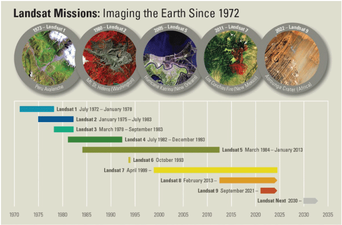
Landsat missions timeline.
Landsat Geometric Calibration and Characterization
Geometric characterization is assessed to determine spacecraft performance, instrument performance, and image product data quality. Geometric calibration is driven by the results of geometric characterization and involves calibration of the spacecraft and instruments. Geometric validation and verification are performed to determine the performance of the spacecraft and instruments. Determining a measure of the ability to accurately calibrate the spacecraft or instrument is also completed. The geometric accuracy of data products distributed to the user community also is assessed.
Geometric correction uses the spacecraft and instrument telemetry and external resources to correct for small random errors in inputs, such as the spacecraft telemetry (for example, position and velocity). Geometric correction also accounts for variables, such as the parallax associated with the instrument viewing geometry using a digital elevation model (DEM).
Ultimately, the objective of applying geometric characterization, calibration, and validation is to produce the most geometrically accurate products possible for the user community.
Geometric calibration and characterization can be divided into two mission life stages: (1) prelaunch and (2) postlaunch. Prelaunch activities include instrument characterization and calibration (for example, focal plane and optics) and spacecraft characterization and calibration (for example, star tracker, gyroscope, and storage). Postlaunch activities include items such as characterization of the instrument roll, pitch, and yaw viewing geometry, as well as interpretation of the image data received.
Geometric correction includes static and measured spacecraft and instrument characteristics. These measurements are provided through spacecraft and instrument telemetry. Examples of dynamic characteristics include spacecraft position, velocity, and attitude. Static characteristics may include focal plane layout or instrument alignment to spacecraft. Spacecraft position, velocity, and attitude are all derived through spacecraft telemetry. Instrument line of sight is determined through static focal plane characteristics combined with spacecraft and instrument telemetry. These focal plane characteristics are assessed during prelaunch and postlaunch calibration of the instrument.
Geometric correction for Operational Land Imager (OLI) and Thermal Infrared Sensor (TIRS) must align detectors, bands, and SCAs (figs. 2, 3). This correction requires knowledge about sensor characteristics, spacecraft and instrument dynamics, and how those factors are affected by the Earth model. Knowing these variables allows for each detector line-of-sight intersection to the Earth’s surface to be determined.
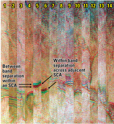
Raw Operational Land Imager Landsat image displaying the within band misalignment among Sensor Chip Assemblies (SCAs) and the band-to-band separation within an SCA when comparing bands 6, 5, and 4.
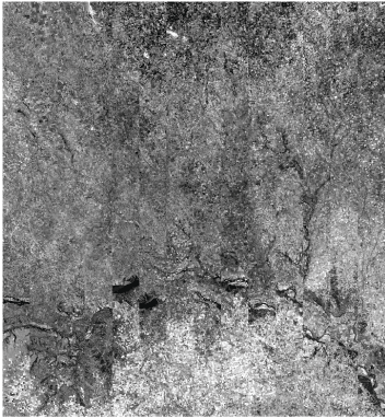
Geometrically raw and radiometrically corrected Operational Land Imager Landsat image showing Sensor Chip Assembly (SCA) to SCA separation for band 1.
Applying geometric corrections to an L1 image produces a geolocated, terrain corrected product. Additionally, the sensor/instrument is radiometrically and geometrically calibrated. Products are geometrically corrected, including accounting for terrain effects, and registered to the Landsat ground control library. The culmination of these steps produces highly accurate radiometric and geometric products that are well registered to each other. For Landsats 8 and 9, an example of geometric calibration coaligns the fields of view for the OLI and TIRS instruments, and seasonal dependencies in TIRS-to-OLI alignment are characterized, predicted, and corrected for.
Landsats 8 and 9 on-orbit geometric performance is verified via band registration accuracy, OLI to TIRS alignment, geometric accuracy, geodetic accuracy, and Landsat 9 to Landsat 8 OLI geometric coregistration (figs. 4, 5, 6).
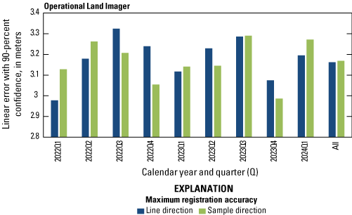
Landsat 9 Operational Land Imager lifetime band (excluding cirrus) registration accuracy by quarter.
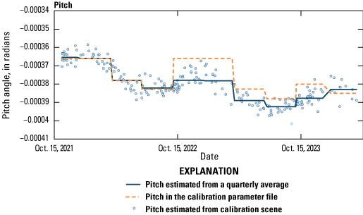
Landsat 9 Thermal Infrared Sensor to Operational Land Imager lifetime pitch alignment.
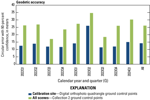
Landsat 8 lifetime geodetic accuracy by quarter.
Landsat Radiometric Calibration and Characterization
Factors like sensor artifacts, viewing and illumination angles, or atmospheric conditions affect Landsat data’s digital number (DN) values. Monitoring and regular characterization of sensor data are required to maintain radiometric calibration and stability of Landsat products and improve algorithms and processes used in product generation.
Uncertainty informs users about the confidence in a measurement. No measurement can provide an exact representation of a target radiance/reflectance, but an uncertainty estimate, along with a measurement, provides a range that should contain the true value. The Landsat mission strives to provide measurements with the lowest uncertainty.
The radiometric calibration of Landsat 8’s OLI is required to be metrologically traceable to the standards set by the National Institute of Standards and Technology (NIST). The transfer of radiometric calibration from NIST sources to OLI and the acquired Earth image data can be impacted by various effects and their uncertainties such as spectral response, nonlinearity, nonuniformity, stray light, any transmissive elements, and radiance sources and their stability (U.S. Geological Survey, 2024).
The Cal/Val team monitors the performances of Landsats 8 and 9 data daily by trending the results of radiometric and geometric algorithms processed on all data (fig. 7). Through regular evaluation of the stored results in the database, changes in instrument behavior can be monitored and corrected over time. The Cal/Val team monitors sensor changes and determines when it is necessary to update the Calibration Parameter Files (CPFs), Bias Parameter Files, and Response Linearization Look Up Tables to create better image products, while maintaining a level of consistency for comparability through time.
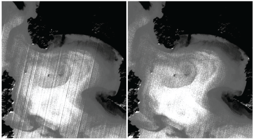
Samples of a Thermal Infrared Sensor band 10 image with radiometric striping after initial processing and the reduction of striping when reprocessed with updated processing parameters.
For the OLI system, prelaunch radiometric testing included collection of the Focal Plane Assembly (FPA) response datasets that track instrument responses. These collects follow NIST traceability standards and establish the absolute radiance scale of the OLI system. Additional radiometric scale-related collects that occurred prelaunch involved datasets that defined the OLI full-system relative spectral response data and sequences that evaluated the OLI system noise as well as response stability and repeatability over various time intervals. All of these collects and follow-on analysis established the per-band prelaunch radiometric scales’ total uncertainties (table 1).
Table 1.
Landsat 8 Operational Land Imager prelaunch per-band radiometric uncertainty estimates (values expressed in percentage).[*, multiplied by; Ltypical, typical radiance; LMax, maximum value of spectral radiance; NIR, near infrared; SWIR, short-wave infrared]
The spatial response of TIRS was first assessed in prelaunch testing under flight-like thermal vacuum conditions. Postlaunch, coastline targets were identified to evaluate the spatial response.
Landsats 8 and 9 on-orbit radiometric performance is verified via OLI signal-to-noise ratio (SNR), TIRS noise performance, radiometric stability, relative gains, and Landsat 9 to Landsat 8 radiometric cross-correlation. The SNR for each of the OLI spectral bands is characterized at a prescribed band-specific typical radiance (Ltypical) level. The SNR of a detector at a given radiance level is defined as the mean of the measured pixel radiances acquired over a homogenous target divided by their standard deviation. A curve is fit to the SNR at the measured radiance levels and is evaluated at the prescribed Ltypical level. The SNR was characterized at multiple stages of the instrument build before launch, culminating in the testing of the fully integrated instrument. Landsats 8 and 9 OLI SNR is evaluated on orbit each month using onboard calibrator data (figs. 8, 9, 10).
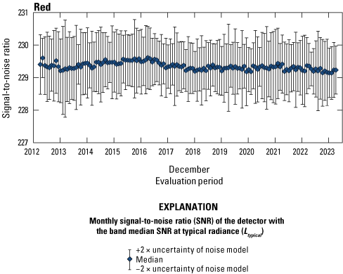
Landsat 8 Operational Land Imager red band lifetime signal-to-noise ratio stability.
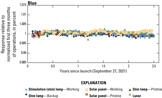
Landsat 9 Operational Land Imager blue band lifetime radiometric stability.
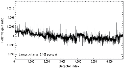
Landsat 9 Operational Land Imager coastal/aerosol band per detector change in relative gains between quarter 4, 2023, and quarter 1, 2024.
References Cited
Haque, M.O., Hasan, M.N., Shrestha, A., Rengarajan, R., Lubke, M., Shaw, J.L., Ruslander, K., Micijevic, E., Choate, M.J., Anderson, C., Clauson, J., Thome, K., Barsi, J., Kaita, E., Levy, R., Miller, J., and Ding, L., 2024, ECCOE Landsat quarterly calibration and validation report—Quarter 1, 2024: U.S. Geological Survey Open-File Report 2024–1058, 57 p. [Available at https://doi.org/10.3133/ofr20241058.
U.S. Geological Survey, 2024, Landsat radiometric uncertainty—EROS Cal/Val Center of Excellence (ECCOE): U.S. Geological Survey website, at https://www.usgs.gov/landsat-missions/landsat-radiometric-uncertainty.
For more information contact:
U.S. Geological Survey, Earth Resources Observation and Science (EROS)
EROS Cal/Val Center of Excellence (ECCOE) Project team
47914 252nd Street
Sioux Falls, SD 57198
Email: eccoe@usgs.gov
Disclaimers
Any use of trade, firm, or product names is for descriptive purposes only and does not imply endorsement by the U.S. Government.
Although this information product, for the most part, is in the public domain, it also may contain copyrighted materials as noted in the text. Permission to reproduce copyrighted items must be secured from the copyright owner.
Suggested Citation
Shaw, J., Anderson, C., Choate, M., and Micijevic, E., 2024, Landsat geometric and radiometric calibration and characterization: U.S. Geological Survey Fact Sheet 2024–3039, 4 p., https://doi.org/10.3133/fs20243039.
ISSN: 2327-6932 (online)
| Publication type | Report |
|---|---|
| Publication Subtype | USGS Numbered Series |
| Title | Landsat geometric and radiometric calibration and characterization |
| Series title | Fact Sheet |
| Series number | 2024-3039 |
| DOI | 10.3133/fs20243039 |
| Publication Date | October 11, 2024 |
| Year Published | 2024 |
| Language | English |
| Publisher | U.S. Geological Survey |
| Publisher location | Reston, VA |
| Contributing office(s) | Earth Resources Observation and Science (EROS) Center |
| Description | 4 p. |
| Online Only (Y/N) | Y |


