

Standardized Method for Logging Drill Core at the Idaho National Laboratory, Idaho
Links
- Document: Report (5.49 MB pdf) , HTML , XML
- Appendixes:
- Appendix 1 (57 KB xlsx) - Digital Logbook
- Appendix 1 (4.86 KB zip) - Digital Logbook (in CSV format)
- Download citation as: RIS | Dublin Core
Abstract
The U.S. Geological Survey’s (USGS) Lithologic Core Storage Library (CSL) at the Idaho National Laboratory stores more than 120,000 feet of drill core that is accessible to the public for research and sampling. To effectively convey the physical and descriptive properties of the drill core, USGS staff at the Idaho National Laboratory Project Office log the drill core and publish the lithologic logs as data releases. The logs provide essential data on the lithology, texture, mineralogy, alteration, and other physical properties of the core, which serve as valuable information for researchers to guide their research and sampling efforts. To ensure consistent, quality, and dependable lithologic logs, this document outlines the procedures and expectations for logging drill core at the CSL. This document describes the processes for storing, photographing, and logging core, and includes a variety of resources, reference materials, and appendixes designed to standardize and aid the logging process. Following the procedures outlined in this document will produce consistent, detailed logs that facilitate dependable observations and serve as an easy reference for researchers and other interested parties.
Introduction
The Idaho National Laboratory (INL) operated by the U.S. Department of Energy (DOE) encompasses about 890 square miles (mi2) of the eastern Snake River Plain in southeastern Idaho (fig. 1). The INL was originally established as the National Reactor Testing Station by the U.S. Atomic Energy Commission (now the DOE) in 1949 to develop atomic energy and to conduct nuclear safety and defense program research. In the modern day, the INL focuses on developing advanced energy concepts and energy solutions to ensure the future security of the Nation’s energy resources and technologies.
Throughout developing these energy concepts, the INL has generated wastewaters contaminated with chemical and radioactive constituents. The INL has disposed of wastewater contaminated with radioactive and chemical constituents in injection wells, infiltration ponds, and trenches. Infiltration of the wastewater into the subsurface and its potential migration to the underlying Snake River Plain aquifer has encouraged ongoing subsurface stratigraphy and hydrology studies of the eastern Snake River Plain at and near the INL. Data collection on the geologic, hydrologic, paleomagnetic, geophysical, and geochemical properties of the subsurface supports conceptual and numerical models used in predicting potential groundwater migration and contaminant transport pathways (Anderson and Lewis, 1989; Anderson, 1991; Anderson and Bartholomay, 1995; Anderson and Bowers, 1995; Anderson, Ackerman, and others, 1996; Anderson, Liszewski, and Ackerman, 1996; Anderson and Liszewski, 1997; Ackerman and others, 2006, 2010).
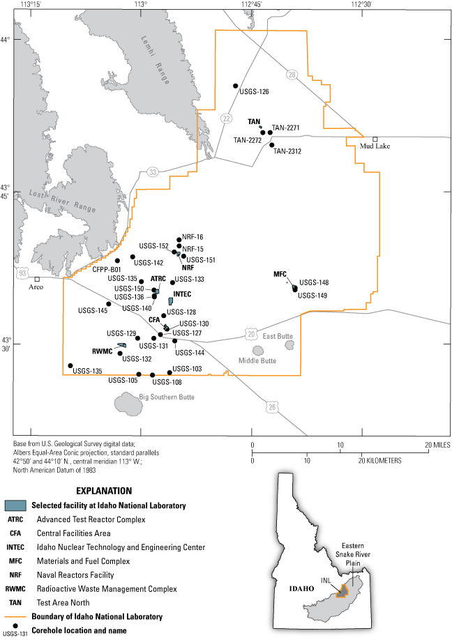
Map showing location of selected coreholes, with available data, and selected facilities at the Idaho National Laboratory, Idaho.
Material for data collection on subsurface lithologies is provided by drill core, a vital resource that supplies abundant material for sampling eastern Snake River Plain rocks. Since the 1950s, more than 500 test holes, auger holes, and coreholes have been drilled to characterize the subsurface geology and hydrology of the eastern Snake River Plain at and around the INL (Hodges and others, 2018). The material from these coreholes, defined herein as drill core, directly archive subsurface stratigraphy and provide abundant igneous and sedimentary layers for sampling and geologic data collection. However, for researchers to conduct data collection, the drill core must be consolidated, stored, cataloged, and accessible.
In 1990, the INL Lithologic Core Storage Library (CSL) was established to consolidate, store, and catalog non-radioactive drill cores and cuttings from eastern Snake River Plain and nearby coreholes (Hodges and others, 2018). Before 1990, many drill cores were lost, disposed of, or exposed to the elements, which led to the loss of important contextual and technical information needed for detailed geologic studies. As of 2018, the CSL contains over 120,000 feet (ft) of drill core sourced primarily from the eastern Snake River Plain. The stored drill core provides a valuable resource for conducting various subsurface geologic studies. However, for the drill core to be used fully, the available drill core and their lithologies must be known, documented, and described. Lithologic core logs present a way to describe and visualize features of the drill core, which communicates what material is available for sampling and guides sample collection.
To support USGS personnel and other researchers in their research efforts, the USGS Idaho National Laboratory Project Office (INLPO) logs drill core stored in the CSL and publishes these lithologic core logs (table 1; fig. 1). A core log consists of a series of observations of a stratigraphic column of core, ensuring comprehensive descriptions while minimizing interpretations. While the observations a logger records depend on lithology and the purpose for logging, most core logs often include observations on lithology, color, texture, mineralogy, and alteration. The observations recorded in a core log provide important lithologic context for researchers interested in conducting geochemical, paleomagnetic, subsurface, and other geological analyses. To effectively record and communicate important lithologic, textural, and mineralogical observations, the procedures for logging drill core must be defined and standardized. Therefore, the purposes of this report are to define the components of a lithologic core log produced by INLPO personnel and interns, describe the procedures for logging drill core, and attach supporting reference materials to aid the logging process.
Table 1.
Corehole locations, identifiers, and lithologic core log information for cores logged following the USGS Idaho National Laboratory Project Office protocol and stored at the Lithologic Core Storage Library.[“Borehole name” column lists the common identifier used in this study. “Site number” column displays unique numerical identifier used to access borehole data (U.S. Geological Survey [USGS], 2024). Latitude and longitude are taken at brass survey marker located adjacent to the borehole head on a cement pad and are in decimal degrees. “Land-surface altitude” is in feet above the North American Vertical Datum of 1988 (NAD 88). “Total depth” is depth in feet below land surface of the borehole and corresponds to the stratigraphic thickness of the core. “Reference of published lithologic core log” column lists the publication containing the lithologic core log for that borehole.]
| Borehole name | Site number | North latitude | West longitude | Land-surface altitude | Total Depth (feet) | Reference of published lithologic core log |
|---|---|---|---|---|---|---|
| CFPP-B01 | 433814113031801 | 43.637233 | 113.055125 | 5,094.00 | 1,338 | (Dietz, 2025) |
| NRF-15 | 433942112545001 | 43.661622 | 112.914886 | 4,845.37 | 759 | (Hodges and others, 2012) |
| NRF-16 | 434018112545101 | 43.671650 | 112.915108 | 4,831.05 | 425 | (Hodges and others, 2012) |
| TAN-2271 | 435053112423101 | 43.848056 | 112.709408 | 4,784.42 | 289 | (Twining and others, 2016) |
| TAN-2272 | 435053112423001 | 43.847939 | 112.725931 | 4,784.69 | 287 | (Twining and others, 2016) |
| TAN-2312 | 434939112422001 | 43.827603 | 112.705436 | 4,796.00 | 568 | (Twining and others, 2018) |
| TAN-2336 | 435053112423203 | 43.847933 | 112.708861 | 4785.77 | 256 | (Twining and others, 2023) |
| USGS-103 | 432714112560701 | 43.453678 | 112.935975 | 5,010.82 | 1,307 | (Hodges and others, 2012) |
| USGS-105 | 432703113001801 | 43.450853 | 113.005769 | 5,098.58 | 1,409 | (Hodges and others, 2012) |
| USGS-108 | 432659112582601 | 43.449572 | 112.974814 | 5,034.79 | 1,218 | (Hodges and others, 2012) |
| USGS-126a | 435529112471301 | 43.924561 | 112.787750 | 4,992.25 | 648 | (Twining and others, 2008) |
| USGS-126b | 435529112471401 | 43.924492 | 112.787961 | 4,992.81 | 472 | (Twining and others, 2008) |
| USGS-127 | 433058112572201 | 43.516097 | 112.956953 | 4,959.91 | 598 | (Twining and others, 2008) |
| USGS-128 | 433250112565601 | 43.547092 | 112.949583 | 4,938.40 | 768 | (Twining and others, 2008) |
| USGS-129 | 433036113002701 | 43.510050 | 113.004560 | 5,029.68 | 779 | (Twining and others, 2008) |
| USGS-130 | 433130112562801 | 43.525094 | 112.942053 | 4,931.02 | 723 | (Twining and others, 2008) |
| USGS-131 | 433036112581601 | 43.509986 | 112.971956 | 4,980.77 | 1,239 | (Twining and others, 2008) |
| USGS-132 | 432906113025001 | 43.485094 | 113.048314 | 5,032.08 | 1,238 | (Twining and others, 2008) |
| USGS-133 | 433605112554301 | 43.601419 | 112.929647 | 4,893.62 | 812 | (Twining and others, 2008) |
| USGS-134 | 433611112595801 | 43.603003 | 113.000353 | 4,972.38 | 949 | (Twining and others, 2008) |
| USGS-135 | 432753113093601 | 43.464758 | 113.160731 | 5,139.38 | 1,198 | (Hodges and others, 2012) |
| USGS-136 | 433447112581501 | 43.579828 | 112.970831 | 4,938.51 | 1,048 | (Twining and others, 2012) |
| USGS-140 | 433441112581201 | 43.577939 | 112.970831 | 4,940.02 | 546 | (Twining and others, 2014) |
| USGS-142 | 433837113010901 | 43.643606 | 113.020117 | 4,995.32 | 1,880 | (Twining and others, 2017) |
| USGS-144 | 433021112552501 | 43.505714 | 112.924439 | 4,954.22 | 639 | (Trcka and Twining, 2023a) |
| USGS-145 | 433358113042702 | 43.566178 | 113.074161 | 5,134.87 | 1,368 | (Trcka and Twining, 2023b) |
| USGS-148 | 433535112390801 | 43.593172 | 112.652089 | 5,140.55 | 759 | (Twining and others, 2021) |
| USGS-148a | 433535112390801 | 43.593172 | 112.652089 | 5,140.55 | 759 | (Twining and others, 2021) |
| USGS-149 | 433524112390800 | 43.589925 | 112.652300 | 5,132.42 | 974 | (Twining and others, 2021) |
| USGS-150 | 433521112581801 | 43.589278 | 112.971611 | 4935.00 | 1,400 | (Trcka and Twining, 2025) |
| USGS-151 | 433846112540701 | 43.644839 | 112.904639 | 4,853.25 | 1,720 | (Trcka and Twining, 2023c) |
| USGS-152 | 433906112553401 | 43.651761 | 112.926075 | 4,853.98 | 1,259 | (Trcka and Twining, 2023d) |
| USGS-152a | 433906112553401 | 43.651761 | 112.926075 | 4,853.98 | 1,259 | (Trcka and Twining, 2023d) |
| USGS-152b | 433906112553401 | 43.651761 | 112.926075 | 4,853.98 | 1,259 | (Trcka and Twining, 2023d) |
Purpose and Scope
The CSL continuously receives and stores drill core from ongoing INLPO drilling projects. To describe the subsurface stratigraphy of the eastern Snake River Plain and material available for sampling, CSL personnel log the drill cores. Because multiple individuals log various drill cores, following a standardized logging procedure ensures consistent and quality data collection. The purpose of this document is to outline the standard procedures for creating a lithologic core log, which includes photographing and logging the drill core. Recognizing that a single system may not be applicable to all circumstances, this report documents the required details in a log, the procedures to follow when logging, and includes appendixes and references to ensure consistent naming, recognizing, and defining schemes across different individuals and drill cores. Following the procedures outlined in this report will generate lithologic core logs with consistent and reliable observations, which facilitates quick reference, effective communication, and easy comparison across different drill cores.
Geologic Background
The Idaho National Laboratory (INL) resides on the eastern Snake River Plain, which is an east-northeast trending topographic depression that extends from Twin Falls to Ashton, Idaho (Leeman, 1982). The eastern Snake River Plain developed as the North American tectonic plate migrated southwestward over a fixed, upper mantle melting anomaly beginning around 17 million years ago (Pierce and Morgan, 1992; Pierce and others, 2002; Morgan and McIntosh, 2005). This melting anomaly is often referred to as the Yellowstone hotspot. The track of the North American plate over the Yellowstone hotspot produced a time-transgressive series of silica-rich volcanic fields that young from west to east (Braile and others, 1982; Anders and Sleep, 1992; Peng and Humphries, 1998; Rodgers and others, 2002; Shervais and others, 2006). In the wake of the Yellowstone hotspot, the track subsided and created the arcuate depression in southern Idaho known as the Snake River Plain (Braile and others, 1982; Anders and Sleep, 1992; McQuarrie and Rodgers, 1998; Rodgers and others, 2002). In the eastern Snake River Plain, the subsidence created accommodation space for a 1–2-kilometer-thick package of plains-style basaltic lava flows interbedded with eolian, fluvial, and alluvial sediments (Greeley, 1982; Kuntz and others, 1992; Peng and Humphreys, 1998; Hughes and others, 2002; Potter and others, 2019).
Volcanism on the eastern Snake River Plain is representative of plains-style volcanism (Greeley, 1982). Plains-style volcanism is characterized by fissure eruptions from shield volcanoes that produce voluminous tube-fed pahoehoe flows. Shield volcanoes produce individual lava flows that range from <1–40 meters (m) thick, extend as far as 40 kilometers (km) away from the source vent, and cover an area as much as 155 square meters (m2) (Kuntz and others, 1992).
Most of the basalt flows on the eastern Snake River Plain classify as olivine tholeiites and are petrographically and geochemically similar to each other (Leeman, 1982). Eastern Snake River Plain olivine tholeiites contain olivine, plagioclase, clinopyroxene, ilmenite, magnetite, glass, and accessory apatite. Rocks of more evolved compositions are also found in the eastern Snake River Plain, such as at Craters of the Moon, Cedar Butte, and the Spencer-High Point area (Kuntz and others, 1992).
Lithologies present in drill cores stored at the CSL include unconsolidated sediment, consolidated sediment, basalt, and intermediate to felsic igneous rocks such as rhyolite. While the most common lithology is basalt, individual basalt flows are often interbedded with sediment and rhyolite is expected in deep (>1000 feet) drilling projects. Any person logging core at the CSL should expect to encounter any of these lithologies. The following sections describe how to recognize, name, and describe basalt, rhyolite, and sediment in CSL cores.
Lithologic Core Storage Library
The Lithologic Core Storage Library (CSL) is a 6,163 square feet (ft2) building located at the Central Facilities Area of the Idaho National Laboratory (INL) (fig. 2a). The building consists of 4,110 ft2 of core storage space, 1,340 ft2 of laboratory space, including a separate room for sampling, 420 ft2 of office space, a 143 ft2 restroom, and a 150 ft2 mechanical room for heating, cooling, plumbing, and electrical systems (Hodges and others, 2018; fig. 2b). An additional 6,400 ft2 of core storage space is allocated in a separate building called “The Annex” (fig. 2a). It is recommended that all core is logged at the CSL because of better lighting, equipment, and table space. CSL personnel are available to move core between the buildings upon request. In the event of future building migration and consolidation, building functionality, building use, and logging procedures will largely remain unchanged.
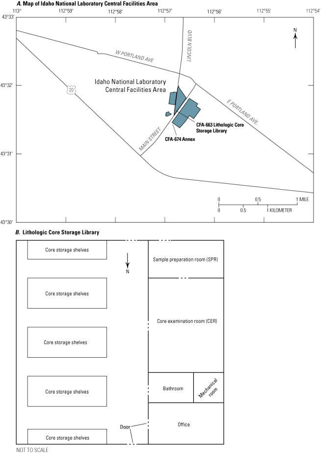
Maps displaying the location of A, the Lithologic Core Storage Library (CSL) and Annex at the Idaho National Laboratory and B, the internal layout of the CSL.
The main area for logging and working with core is the core examination room (CER) of the CSL (fig. 2b). The core examination room includes multiple tables that can accommodate up to 600 feet of core and examination equipment such as binocular and petrographic microscopes, hand lens, and various hand tools. The CER also contains resources for logging core following the methods outlined in this report, including color charts, photographic jig stand, and printed copies of the appendixes included in this report.
The main area for sampling or altering core is the sample preparation room (SPR), which is attached to the CER (fig. 2b). The sample preparation room includes equipment such as drying ovens, an oil-cooled rock saw, a water-cooled rock saw, two drill presses with 0.5–l.0 inch-diameter coring bits, petrographic microscopes, balances, mechanical sediment shaker and sieves, and an array of standard laboratory glassware and equipment.
The main area for managing the databases and records related to the drill core is the office. The office also provides workspaces and office equipment such as a printer and scanner for visitors as needed. The manager of the CSL is referred to as the Core Storage Library Custodian, often shortened to Core Library Custodian, and is the main point of contact for any visitor. Interested visitors should visit the INLPO’s website at https://www.usgs.gov/centers/idaho-water-science-center/science/inlpo-core-storage-library. A visitor must obtain prior permission and approval before traveling to the CSL for any purpose, which includes logging and sampling. Visitors are allowed to use any of the provided equipment for logging and sampling. However, visitors must obtain prior approval before bringing any analytical electronics or chemicals because of potential requirements or restrictions by the INL. Visitors must bring the user manual for analytical electronics and safety data sheets for any chemicals that they bring to the CSL. All visitors must sign in using the log provided at the main entry of the CSL. For researchers, institutions, companies, and other parties that are interested in storing core at the CSL, please see Hodges and others (2018).
Logging Procedures
A lithologic core log is a series of recorded observations of a drill core along set intervals. The specific contents of a lithologic core log depend on a wide variety of factors, including lithology, the overall purpose of logging, and the individual practices of the person logging the core (referred to herein as the “logger”). Every Idaho National Laboratory Project Office (INLPO) core log will contain core photographs, a lithologic description that describes the physical and visual properties of the drill core, an evaluation of the fracture frequency, an evaluation of vesicle size and concentration, and the type and location of any sedimentary and igneous structures. The most important aspect of the lithologic core log is the lithologic description. The lithologic description contains a detailed lithologic name and a description of the color, texture, composition, and alteration of the given interval. Additional information is added to the lithologic description or other parts of the core log depending on if the rock is sedimentary or igneous. For example, basalt intervals include a description of vesicle size and concentration, and sedimentary intervals contain a description of biological activity. The specific aspects of a core log for each lithology and how to collect that data are described in more detail in the “Core Descriptions” section of the report.
Procedures Before Logging
In general, most drill cores are stacked on pallets that are placed on 0- (ground level) to 15-foot-high shelves. The pallet containing the drill core is removed from the shelves by Core Storage Library (CSL) personnel that have passed all Idaho National Laboratory certifications for forklift operation. Pallets are placed using a pallet jack or forklift near the doorway of the CER. Before transporting the core from the pallet to the CER, it is recommended to take a picture of the core boxes on the pallet. The picture can be used as a reference to ensure that the boxes are returned to the pallet in the proper orientation and order, saving time and limiting future confusion and frustration. Core boxes are then removed from the pallet and either walked to the CER or carted using a trolley, which has a weight limit of around 300 pounds.
The person lifting and transporting core needs to follow safe lifting practices and wear protective equipment, including gloves and closed-toe shoes. Safe lifting practices include lifting core with a secure grip on the top and bottom of the box, using two hands, and not attempting to lift more than what can reasonably be carried. It is important to be mindful that not all core boxes weigh the same. The total weight of the core box depends on the size of the core, the type of box the core is stored in, and the lithology and amount of the core in the box itself. Most core boxes stored at the CSL weigh between 25–50 pounds. When walking core from the pallet to the CER, a person should be mindful of their surroundings to prevent damage to the core, other people, to their fingers and to their toes. If a core box has deteriorated while in storage, the box should be transported using a trolley or lifted with the support of multiple people.
Core Layout
The tables of the CER can hold between 500–600 feet of core, which amounts to about 60 boxes of core or one and a half pallets. Before laying out the core boxes, the logger should ensure that the work area and tables are clean and clear from clutter. A clean area limits contamination, maintains a safe working environment, and removes potential tripping hazards that can lead to personal injury and dropped boxes.
Maintaining proper core orientation and the correct order of boxes facilitates easier and more accurate data collection. However, knowing which way the core is oriented in the box can be challenging, especially because USGS-drilled and contractor-drilled core often have different orientations (fig. 3). There are a few indications in any core box that the logger can use to determine top from bottom and deep from shallow. Many cores, especially those drilled by the USGS, are marked with two parallel lines colored red and blue (fig. 3a). When the core is properly oriented, or where shallow is at the top and deep is at the bottom, the red line is always on the right side of the core.
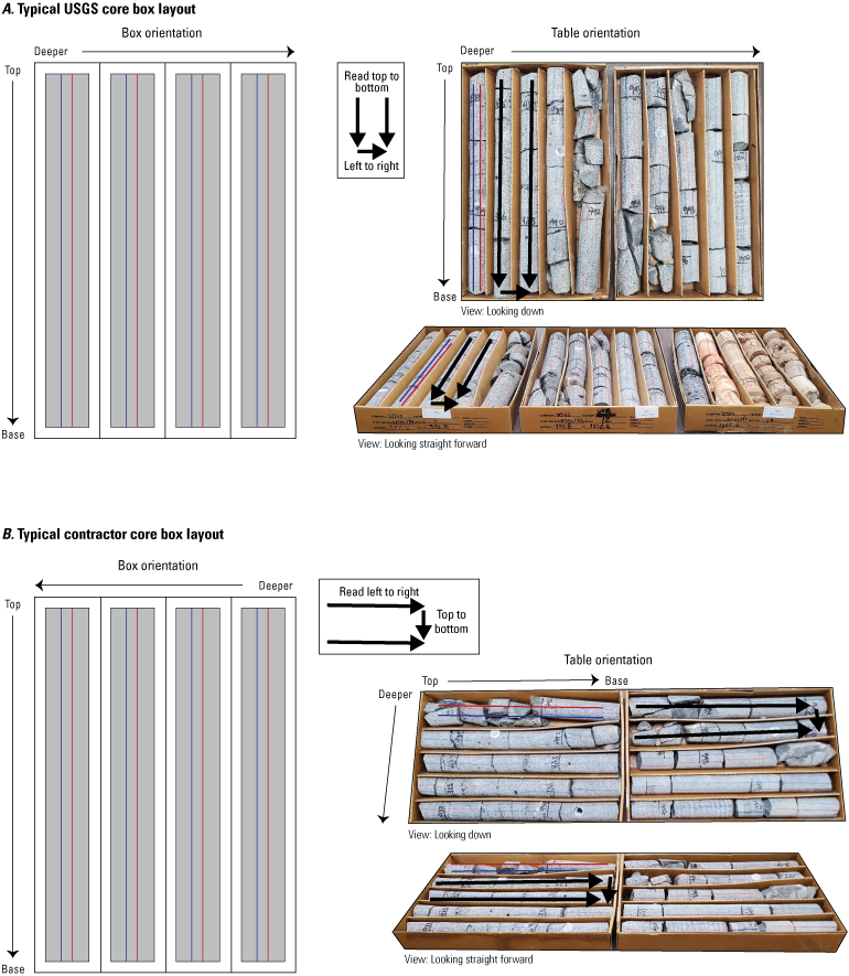
Diagram illustrating the box orientation (left) and table placement (right) of (A) USGS and (B) contractor-drilled core placed in core boxes.
The orientation of the core is also directly indicated by depth markings, where more shallow depths are expected at the top of the box and deeper depths are expected at the base of the box (fig. 3). Depth is frequently marked on the core itself in permanent marker and often indicated by writing on wooden or foam blocks, core boxes or lids, and other pieces. Knowing the depth of the core is vitally important for logging and sampling. Therefore, a logger must also confirm that the depths on the core are marked properly and that all missing intervals are accounted for. The logger should pay special attention to rubbly intervals, sedimentary interbeds, and lithologic contacts when confirming depths and missing intervals because these areas often have low recovery, which can be challenging to measure and indicate properly.
The logger should use as many of the orientation and depth indicators as possible to determine proper core orientation and placement because the core could have been misplaced or mislabeled. If drill core has been marked incorrectly, multiple depth indicators do not match, there are missing intervals that have not been indicated or recorded within the core box, or if there are any other questions, the logger should alert the CSL Custodian. Working with the CSL Custodian, the logger may properly orient and mark the drill core by using any of the orientation indicators and additional resources such as drilling and sampling notes. Marking the core includes adding red and blue orientation lines or adding or altering depth indicators where appropriate.
Core Photographs
Every box of core needs to be photographed before being logged. A photograph of a box of core serves many purposes, including:
-
• Visually representing the core without interpretation or description.
-
• Offering a tangible product if the core is lost or destroyed.
-
• Providing context for physical descriptions.
-
• Aiding reconstruction of core if the box is dropped or core is misplaced.
At the INLPO, core is photographed using a specially designed photographic jig (fig. 4). Using the jig for photographing ensures consistent lighting, reduces artifacts caused by lighting such as glare, and includes metadata information like corehole name, box orientation, and interval depth.
The photographic jig remains in the CER, though it is not permanently affixed to any location. If necessary, the logger should move the jig with permission and help from CSL personnel to a safe, secure, and accessible location. Before photographing, the logger should ensure that the jig is set up properly (fig. 4) by checking for the following:
-
• Lights on the jig are pointed at opposite ends of the box.
-
• Arms holding the lights are oriented at 60 degrees.
-
• Mirror and camera mount are attached and secure.
-
• Jig is plugged in.
-
• Lights are not burned out and roughly emit the same amount of light.
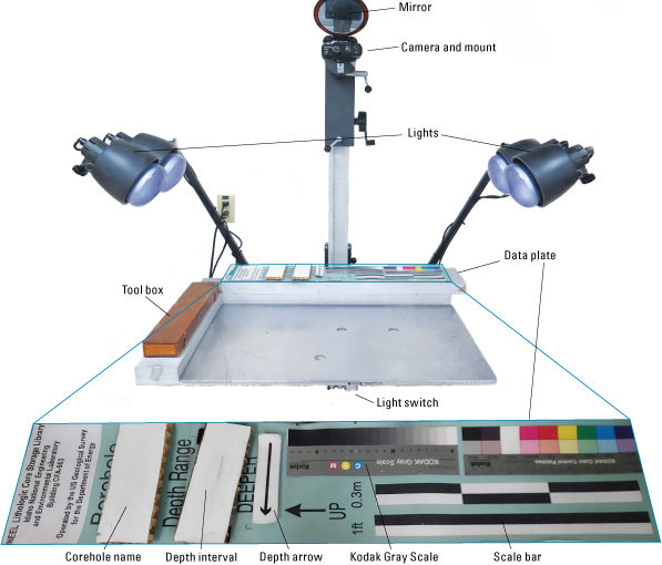
Annotated photographs of the photographic jig and data plate used to take and process core box photographs at the Lithologic Core Storage Library.
The CSL keeps and maintains multiple handheld, digital cameras for photographing core. CSL personnel will show the logger where the cameras, spare batteries, and battery chargers are stored, as well as provide verbal instruction on camera maintenance and use. Before securing the camera to the jig, the logger should ensure that the camera is set-up properly by checking for the following:
-
• SD card and battery are in the camera, free from corrosion, and have available storage space.
-
• Lens protector is removed and stored safely.
-
• Lens and digital screens are clean and free from dust and smudges.
-
• Camera is on.
-
• Mode wheel on the camera is set to “auto.”
-
• Flash is off.
-
• External trigger is attached to the camera.
Once the camera is set up properly, the logger can attach the camera to the jig. The camera screws into the back arm of the jig through a pilot hole on the bottom of the camera. Before tightening the camera completely, ensure that the camera is level by using the bubble level in the jig toolbox (fig. 4). Place the bubble level on the flattest part of the camera and use the mirror to make adjustments as needed. Once leveled, tighten the screw just until the camera is snug. Use the mirror to check that the core box and data plate will be within the frame of the picture. Adjust the height of the camera on the arm as needed by using the levers.
With the camera and the jig set up properly, the logger can begin to take photographs by placing each core box on the jig. The long axis of the core box is always placed against the long axis of the jig, but the exact orientation of the box is controlled by depth direction. The core box must be placed in the jig where the core orientation follows the directions of the “up” and “depth” arrows on the jig (fig. 4). If needed, the depth arrow can be replaced with an arrow going the opposite way. If the arrow placements still do not align with the core orientation, alert the CSL Custodian before taking any pictures. Once the core box aligns with the arrows, the logger should push the box until it is flush against the back rest and the data plate and is positioned squarely. The logger needs to write the name of the corehole and the depth interval represented in core box using legible handwriting in the designated areas, which are labeled “corehole name” and “depth interval” in figure 4. The name of the corehole remains the same throughout all pictures and does not need to be erased and rewritten before each picture, unless the logger is photographing drill core from multiple coreholes. The depth interval changes for each core box and does need to be rewritten before each photograph. The depth interval is often found written on the box or its corresponding lid and needs to be recorded on the jig in the same precision as it was found. Before taking the picture, the logger should ensure that the red and blue parallel lines (fig. 3) as well as other depth indicators will be clearly visible in the photograph.
To take the picture, the logger holds the trigger, steps away from the box, and depresses the button on the trigger. The camera should be set to auto focus, so there is no need to manually focus here. To produce consistent and quality core photographs, the logger should:
-
• Take pictures of core within the same day or at similar times of day to avoid inconsistent lighting.
-
• Turn off all lights and close all blinds and doors to limit the light source in the room to only the light coming from the jig.
-
• Avoid casting a shadow on the core box when taking a picture.
-
• Periodically check the camera orientation and jig stability because placing and removing core boxes can jostle equipment.
-
• Ensure that no cords, extra equipment, or other material is obstructing the photograph.
Core Photographs Post-Processing
Once all core boxes have been photographed or the logger is finished photographing for the day, the logger should:
-
• Return the jig to its normal state: turn off the jig lights; wipe away all dry-erase writing; unscrew the camera from the mount.
-
• Take care of the camera: unplug the trigger and return it to the camera case; remove the battery and charge it, even if the camera was not used for very long; remove the SD card and place somewhere safe.
-
• Clean up the jig and surrounding areas: use a brush to remove any dust or rock fragments that fell on the base of the jig; return any equipment and tools that were used back to their normal location so they may be found easily for the next time.
-
• Turn off all lights and close the door if leaving the CER after photographing.
As soon as practical, the logger should transfer the core photographs from the SD card to an internal INLPO file server to prevent potential loss and support data archiving (fig. 5). Every photograph will include a .jpeg and a raw file. Original photographs should be retained to serve as backup in case other copies are lost, misplaced, or corrupted. If the logger is unable to transfer pictures, alert CSL personnel. CSL personnel will work with the logger to transfer the pictures.
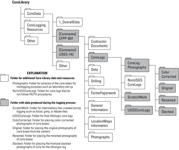
Diagram of select folders of the file tree on the Idaho National Laboratory Project Office’s internal server for file organization and data storage.
Core Descriptions
Standard Practices
There are a few practices that any logger should follow when logging core. These practices include:
-
• Double check that all core boxes are oriented and ordered properly (fig. 3). The core could have become disordered or stored upside-down during photographing.
-
• Remove all lids from the core boxes. There is no correct way to store lids. Make sure that the lids do not obstruct walkways or interfere with the work of others. Lids can be stacked on spare tables, underneath tables, or placed upright with the lip underneath the core box to hold the lid in place. A spare lid can also be used as a table, workstation, or to carry equipment because it is a solid, flat surface that fits easily on a box of core.
-
• Periodically sweep and dust workspace to limit cross-contamination with other drill cores and to keep the work area clean.
-
• Wear sturdy shoes.
-
• Do not eat in the CER. Drinking water in the CER is fine and encouraged.
-
• Remove only a single piece of core at a time to avoid misplacing core. It is also helpful to place some sort of marker such as a pen, foam block, and other pieces of detritus to mark the location of the missing core for easy reference later.
-
• Retain the original integrity of the core. Limit breaking, chipping, or altering the core as much as possible.
-
• Note the interval of any characteristic being described. An interval is given by the top and base in feet below land surface (BLS) of the feature being described, which together is referred to as “depth.”
-
• Log from shallow to deep.
-
• Be mindful of what is described. Consistency is the most important aspect of any lithologic core log. If a specific feature is described in one part of the log, the feature should be described at every other occurrence elsewhere in the log.
-
• The logger ultimately chooses the overall level of detail in the log. Be mindful of time constraints, the overall purpose for the logging, and what others would want to see in the core log.
-
• It is generally faster if the logger chooses one specific characteristic or section of the core log to focus on at a time. This approach helps ensure consistency and limits missing data.
-
• Record the depth in feet BLS to the top and base of each missing interval. This information will be useful for creating the finalized core log. It also reminds the logger to start a new lithologic description after every missing interval.
-
• The logger may record any information collected during the logging process by hand or in the provided digital logbook (app. 1) depending on personal preference.
Lithologic Description
The main aspect of the core log, and the one that contains the most information, is the lithologic description. The lithologic description is a written description of certain characteristics of the drill core such as color, texture, mineralogy, and alteration, though its exact contents vary by the interval of description and its lithology. A lithologic description provides details of the core not visible in pictures and context for sampling. A lithologic description also provides important data and context researchers can use to better understand the geologic history of the area, assess the chemical and physical properties of the different lithologies, and support scientific studies. To create a lithologic description, the logger must be as specific as possible while minimizing interpretation. Ultimately, logging drill core is an individualized experience and always contains some level of interpretation. However, consistency is the key to good lithologic descriptions.
Interval Selection
The first step a logger takes when beginning a lithologic description is choosing the interval of the description. The interval is the depth in feet BLS to the top and to the base of the portion of core being described. The thickness of the interval is dependent on the lithology of the core, the occurrence of missing intervals, and the personal preference of the logger.
On a broad scale, a lithologic core log describes change. Substantial changes in the core, such as a compositional or lithologic change, warrant a new lithologic description to prevent generalizations and loss of detail (fig. 6). Other changes in the core, such as a textural or color change, warrant noting in the lithologic description but not necessarily a new lithologic description. For INLPO core logs, a new lithologic description is required each time the lithology changes regardless of the stratigraphic thickness of that lithology (fig. 6). A change in lithology occurs when the lithology changes from basalt to sediment, or from basalt to rhyolite, for example. A new lithologic description is also required after each missing interval (fig. 6). Even if the lithology immediately above and below the missing interval appears continuous, it is possible the missing interval could have contained a lithologic contact.

An example of a stratigraphic column of a drill core that recommends intervals for the lithologic description based on textures, igneous structures, and missing intervals.
On a fine scale, the same continuous lithologic type should be broken into multiple lithologic descriptions, which is especially true for basalt. Each drill core consists of tens to hundreds of feet of layered basalt flows (fig. 6). A flow refers to all eruptive products from the same eruptive event. Basalt flows can be broken into two or more subdivisions called basalt flow units. A basalt flow unit represents a single eruptive product from an event and therefore defines the minimum subdivision of a basalt flow. It is required at the INLPO for a logger to include at least one lithologic description for every basalt flow (fig. 6). If the basalt flow has multiple flow units, it is recommended the logger create a lithologic description for each flow unit (fig. 6).
Differentiating between basalt flows and layers in drill core can be challenging because of their visual similarities. However, the contact between different flows and layers often produces predictable features that are occasionally preserved in the drill core. These features include oxidation, alteration, flow molds, spatter features, and rubble zones. If the logger notices and recognizes one or more of these features in the drill core along with other features such as missing intervals and distinct mineralogical or textural changes, the logger should initiate a new lithologic description for the basalt package following the observations (fig. 6). Because these features are not unique, the logger does not need to determine or name if the package of basalt is a flow or layer. In general, differentiating between and correlating basalt flows and layers requires additional datasets such as paleomagnetism and geochemistry. However, identifying and defining basalt flows and their flow layers in a core log provides important context for collecting samples for these and other datasets. Ultimately it is up to the discretion of the logger to determine and distinguish between basalt flows and flow layers. While this requires some interpretation, which logging attempts to minimize, a recommended practice is to include more lithologic descriptions rather than less.
Assigning a Generalized Lithologic Name to Intervals
Once the logger has chosen an interval for the lithologic description, the logger must assign a generalized lithologic name to that interval (table 2). An interval can only have a single generalized lithologic name. Assigning a generalized lithologic name is important for maintaining consistent and predictable data collection across multiple loggers and different drill cores. The generalized lithologic name controls the specific components or categories of the lithologic description and therefore the features of the core that the logger describes. The lithologic description itself includes a detailed lithologic name that a logger can use to expand on and refine the generalized lithologic name if possible.
Table 2.
List of categories to include in a lithologic description for each generalized lithologic name, including potential detailed lithologic names.[“Generalized lithologic name” column refers to the name for the interval assigned by the logger and is based on the general lithology of the interval. “Potential detailed lithologic names” column displays a list of expected or potential full lithologic names that correspond to each generalized lithologic name. “Categories” column displays list of topics controlled by the generalized lithologic name to include in the lithologic description of the core log. Abbreviations: HCl, hydrochloric acid]
The generalized lithology for most lithologic units in CSL drill cores will fall into one of the following five categories: basalt, rhyolite, volcanic ash, consolidated sediment, and unconsolidated sediment (table 2). Choosing the generalized lithologic name for the interval is up to the discretion of the logger, and figure 7 presents a flow diagram to help the logger make this choice (fig. 7). If the logger encounters a general lithology that does not fall within one of these five categories, the logger should alert the CSL Custodian and work with the Custodian to determine the new category for the lithologic description.
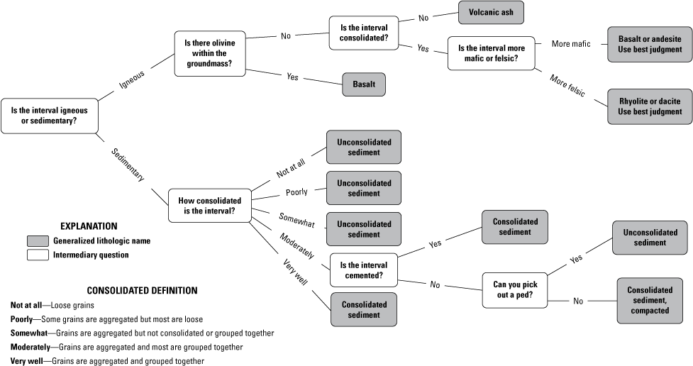
A flow chart displaying generalized lithologic names based on mineralogical evidence and degree of consolidation within the interval.
Many of the basalt flows in drill core are separated by intervals of sediment. The generalized lithologic name of any sediment-bearing interval is controlled by the degree of sediment compaction. For CSL core logs, the two possible generalized lithologic names of the sediment intervals are “unconsolidated sediment” and “consolidated sediment.” Unconsolidated sediment is a sediment interval that consists primarily of loose material. This material ranges from loose, disaggregated grains to large, individual chunks of aggregated grains.
There are two different types of consolidated sediment: cemented and compacted. Cemented sediment consists of grains that are bound together by materials such as quartz, calcite, and iron oxides, which fill the space between grains as the rock forms. Compacted sediment is sediment that has undergone compression, which reduces volume and increases the density of the sediment, because of the weight of the overlying materials. Both cemented and compacted sediment have the same categories for the lithologic description.
Ultimately, it is up to the logger to distinguish between consolidated and unconsolidated sediment. There is a continuous spectrum between consolidated and unconsolidated sediment, and figure 7 presents a flow diagram to help the logger with assigning a generalized lithologic name to a sedimentary interval (fig. 7).
Consistency in naming consolidated and unconsolidated sediment intervals matters more than the name itself. The format of the lithologic description for consolidated and unconsolidated sediment is very similar, which means that similar data are collected for both intervals regardless of their generalized lithologic names. The primary purpose of distinguishing between consolidated and unconsolidated sediment is to facilitate consistent and predictable core logs.
Assigning a Detailed Lithologic Name to Intervals
A detailed lithologic name usually provides more context and information than the generalized lithologic name. A detailed lithologic name is dependent on specific properties of the interval, including texture, grain size, composition, and compaction. If these properties are descriptive only, then the detailed lithologic name and the generalized lithologic name will remain the same. For example, a basalt containing macroscopic minerals is often referred to as “porphyritic basalt.” While “porphyritic” is an important textural term, it describes the lithology of the interval without changing its name. However, if these properties change the overall generalized lithologic name of the interval, then the generalized lithologic name and the detailed lithologic name will diverge. For example, a volcano erupts fragments of rocks, glass, and other materials that can solidify (weld) into a rock called a “tuff” under the right conditions. If the tuff is primarily rhyolitic in composition, then the generalized lithologic name of the interval is “rhyolite” and the detailed lithologic name of the interval is “welded rhyolite tuff.” In this example, rhyolite becomes a descriptive term while “tuff” is the overall name of the rock. Ultimately, it is up to the logger to determine a detailed lithologic name. To assist with this process, figure 8 represents a flow chart that recommends detailed lithologic names based on overall rock type and specific observations expected in CSL drill core (fig. 8). If the logger is unable to assign a detailed lithologic name, the generalized lithologic name may be used as the detailed lithologic name.
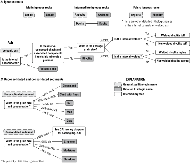
A flow chart displaying detailed lithologic names based on mineralogy and grain size for A, igneous rocks and B, unconsolidated and consolidated sediments.
Igneous rocks, including basalt and intermediate rocks, will always have the same generalized and detailed lithologic name (fig. 8a). While the basalt and intermediate rocks might have unique textures and mineral sizes, these observations qualify rather than alter the generalized lithologic name of the interval. Textures, mineral sizes, and other descriptive features are mentioned in the texture and composition categories of the log and do not need to be included in the detailed lithologic name.
The detailed lithologic name for rhyolite is dependent on how the interval formed and its overall grain size. If the rhyolite was formed as a lava flow cooled, similar to how basalt is formed, the generalized and detailed lithologic name are both “rhyolite.” If a volcano erupted rhyolitic ash that was later welded (consolidated), the generalized lithologic name is rhyolite and a partial detailed lithologic name would be “welded rhyolite.” The detailed lithologic name is further quantified by the dominant grain size in the interval. If the grain size is less than 2 millimeters (mm), the detailed lithologic name is a “welded rhyolite tuff.” If the grain size is greater than 2 mm, the detailed lithologic name is “welded rhyolite tephra.” The groundmass of welded rhyolite tuff and tephra is generally finer grained than rhyolite and includes other eruptive products such as lithics and pumice.
The detailed lithologic name for volcanic ash is dependent on the composition of the ash. The composition of the ash can be basaltic, andesitic, dacitic, or rhyolitic, which depend on the minerals present and their relative abundances. Basaltic ash contains mafic minerals such as biotite and olivine in high quantities, while rhyolitic ashes will contain high quantities of felsic minerals such as quartz and feldspar with few to no mafic minerals. Volcanic ash is assigned to intervals that are not welded, which means the intervals consist of loose ash particles.
Sedimentary Unit Naming
Unconsolidated sediments
The detailed lithologic name for an interval of unconsolidated sediment is based on the dominant grain size of the interval (app. 2, fig. 2.1). Describing the interval based on grain size allows for limited interpretation and easy reference to a dominant feature of the interval. It is important to note that intervals of unconsolidated sediment should not be called “soils.” Calling an interval a soil requires interpretation, which logging avoids as much as possible. In addition, the eastern Snake River Plain has large quantities of loess. Differentiating between soils and loess in drill core is challenging and not expected here.
Consolidated Sediments
The detailed lithologic name of a consolidated sedimentary interval is dependent on the dominant grain size of the interval and the interval’s composition. For fine-grained intervals composed primarily of silt and clay-sized grains (grain sizes <0.008–0.6 mm), naming is based on grain size using the consolidated sedimentary ternary diagram (app. 2, fig. 2.2). For intervals composed primarily of sand-sized grains, naming is based on composition using a quartz-lithic-feldspar ternary diagram (app. 2, fig. 2.3).
To use a ternary diagram, the logger first determines the abundance of each component, represented by the apexes of the triangle, in percent. If the total abundance of the components does not equal 100, the logger must normalize the abundances by adding them together and calculating the percentage of each relative to the total. The logger then finds the point on the ternary diagram that corresponds to the intersection of each normalized abundance. The location of this point on the ternary diagram gives the detailed lithologic name of the interval.
Assigning Color
Describing color follows the same process for every lithology. Color is estimated using a Munsell color chart provided by the CSL. Color must be taken on a weathered (not recently fractured) and non-altered surface of the core that is clear from sediment and drilling artifacts like staining or striation. Every description of color needs to include the alphanumeric code from the Munsell color chart (for example, N7) and its associated description (for example, light gray). If the color of the core does not match an option in the Munsell color chart, the logger should determine the closest match in the Munsell color chart and then briefly describe how the color deviates (for example, N7 light gray with a pale purple tint).
In some cases, the interval chosen for the lithologic description will have multiple different colors. If this is the case, the logger must note the interval of each color. For example, a logger might say N6 medium light gray from (715.0–716.6 ft) and N7 light gray from (716.26–720.1 ft).
In other cases, the interval oscillates between colors on a fine scale of millimeters-centimeters (cm). If this occurs, the logger should note the individual colors using the Munsell color chart, the nature of the contact(s) between the different colors, and estimate a single, average color for the interval. The logger does not need to note the interval of each color because that causes extraneous and tedious data collection beyond the scale the INLPO is looking for.
Assigning Texture
The most important feature of any lithologic description is the texture. The texture describes the overall appearance of a rock, which is controlled by the rock’s evolution and the arrangement of its components like grains or minerals. The texture and its description for any rock are highly dependent on lithology. It is beyond the scope of this document to account for every possible texture in CSL core.
In many cases, the interval chosen for the lithologic description will have multiple different textures. If this is the case, the logger must note the interval of each texture and the degree of the texture if applicable (app. 3, table 3.1). For example, a logger might say vesicular from (131.2–136.4 ft) and vesicular and strongly diktytaxitic from (131.2–136.4 ft).
Igneous Textures
Common igneous textures of basalt, intermediate, and felsic rocks related to appearance include massive, diktytaxitic, and vesicular (table 3). Massive texture occurs in the absence of vesicular and diktytaxitic textures. It is sufficient to note only the interval of vesicular textures because vesicle size and concentration data are collected separately. However, if the vesicles are oriented, elongated, or have other strange characteristics, the logger should note that information here.
Table 3.
Description of select igneous textures, including their definitions and how to recognize them in core stored at the Lithologic Core Storage Library.[“Texture” column lists the name of the texture being described. “Definition” column provides the definition of the texture adapted from the Glossary of Geology by the American Geosciences Institute (2025). “Description” column provides a list of the potential defining features or characteristics of the texture to help the logger identify that texture in the core. “Additional comments” column includes additional descriptions, recommendations for logging, and other characteristics of the texture not included in the previous columns. Abbreviations: cm, centimeter; ft, foot; in, inch; mm, millimeter; N/A, not applicable; %, percent; >, greater than; <, less than]
Sedimentary Textures
For consolidated and unconsolidated sediments, texture refers to select characteristics of the overall sediment grains, including how the grains appear and how they are aggregated together (Compton, 1985; Retallack, 1988). These descriptions are limited by visibility factors such as grain size, lighting, and individual eyesight. A visual description of the sediment grains should include:
-
• Size: A description of the overall range of grain sizes of all grains given in common grain size terms (table 4).
-
• Rounding: A description of the overall range of rounding of all grains given in qualitative terms, where rounding refers to the degree of how round a grain is (fig. 9).
-
• Sorting: A description of the overall range of sorting of all grains given in qualitative terms, where sorting refers to the degree of uniformity in size and degree of roundness of grains in an interval (fig. 10). More uniform intervals indicate better sorting.
For unconsolidated sediments, the overall texture of the interval is also dependent on how the individual grains are packed together and the shape the aggregated grains make, which is called packing. The aggregated grains are called peds. If the grains are completely loose and not connected, there are no peds and the packing of the interval is referred to as single-grained. If there are peds, the peds can form blocky, columnar, or platy shapes, which is reflected in the type of packing (table 5). The texture for every unconsolidated sedimentary interval must include a description of packing using the terms outlined in table 5.
Table 4.
Description of grain size and name.[“Lower diameter and upper diameter” columns give the upper and lower dimensions for each grain size name. “Grain size name” column provides the name given to the grain being described if it falls between the upper and lower dimensions. “Group name” column lists the common, less-detailed name given to the grain sizes. Modified from Wentworth (1922). Abbreviations: mm, millimeter; >, greater than; <, less than]
Table 5.
Description of packing types and how to recognize each type in core stored at the Lithologic Core Storage Library.[“Packing” column provides the name of the type of packing being described. “Definition” column displays the definition of the packing adapted from the Glossary of Geology by the American Geosciences Institute (2025) and Retallack (1988). “Description” column provides a list of potential defining features or characteristics of the packing to help the logger identify that packing in the core. “Additional comments” column provides additional descriptions, recommendations for logging, and other characteristics of the packing not included in the previous columns. Abbreviations: cm, centimeter; mm, millimeter]

Schematic diagram illustrating different degrees of rounding for circular (top) and oblong (bottom) sedimentary grains as modeled after Compton (1985).

Schematic diagram illustrating different degrees of sorting in sedimentary intervals, similar to model in Compton (1985).
Assigning Structures
Also included in the texture category of a lithologic description is a place to note any igneous and sedimentary structures (table 6). It is beyond the scope of this document to account for every possible structure in CSL core.
For any igneous and sedimentary structure, the logger should note the depth (single occurrence, given in feet BLS) or interval (multiple occurrences, given in top and base in feet BLS) of the structure, its recurrence interval (that is, how many times it occurs in the interval), and if the structure seems to be controlled or influenced by any other features of the core (for example, fractures, banding, and grain size change). Using these observations and table 6, the logger also needs to name the structure. If there is a structure present in the core but not mentioned in table 6, the logger should alert the CSL Custodian and describe the structure as much as possible. These descriptions should include the same information mentioned in the “Assigning Composition” section, as well as the shape, overall appearance, and size of the structure.
Common igneous structures include vesicle alignments such as vesicle sheets and vesicle cylinders, emplacement features such as flow molds and spatter, and select textural characteristics such as rheomorphic folding and lithophysae (table 6). Common sedimentary structures include bedding features such as trough-crossbeds, bedding types such as massive, thin, or graded bedding, and additional features such as mud cracks and root casts (table 6). If a logger recognizes any of these structures, the logger should note the depth or interval of the structure and describe any additional information such as size, shape, and extent in the texture category of the lithologic description.
Table 6.
Description of igneous and sedimentary structures, including their definitions and how to recognize each in core stored at the Lithologic Core Storage Library.[“Structure” column provides the name of the structure being described. “Definition” column provides the definition of the structure adapted from the Glossary of Geology by the American Geosciences Institute (2025). “Description” column provides a list of the potential defining features or characteristics of the structure to help the logger identify that structure in the core. “Additional comments” column provides additional descriptions, recommendations for logging, and other characteristics of the structure not included in the previous columns. Abbreviations: cm, centimeter; in., inch; ~, approximately; >, greater than; <, less than]
Assigning Composition
To fully describe the composition of an interval, the logger must describe the visual and physical characteristics of every mineral and other major components like lithics and pumice to the best extent possible. Composition descriptions are limited by visibility factors such as grain size, lighting, and individual eyesight. However, all composition and mineral descriptions should include:
-
• Name: If known, name the mineral being described. If unknown, describe the mineral in the following format and include any other possible identification information like hardness, cleavage, and luster.
-
• Size: Mineral size should be given in mm (table 4). Include maximum and minimum mineral size and any textural terms related to grain size (figs. 9, 10)
-
• Color: Describe the general color of the mineral using common colors; do not use the Munsell color chart. Add qualifiers as needed such as “light” or “dark.” List all the colors or give a range of the colors the mineral exhibits.
-
• Shape: Describe the overall or average shape the mineral has. Include any textural terms related to mineral shape (table 7).
-
• Concentration: Concentration refers to the composition by volume of a macroscopic mineral present in the given interval. Concentration is estimated using best judgement and standardized figures (app. 4). While the most accurate representation of concentration comes from point-counting a thin section, the concentration recorded here can be used to compare relative mineral abundance across different intervals.
-
• Mineral alteration: Describe the type, nature, and visual properties of any altered minerals. Descriptions can include but are not limited to color, name, location of the alteration in the mineral, and any visible controls on the alteration like banding, fractures, or other internal arrangements within the interval.
Table 7.
Description of textural terms used to describe minerals, including their definitions and how to recognize them in core stored at the Lithologic Core Storage Library.[“Texture” column provides the name of the mineral texture being described. “Definition” column provides definition of the texture adapted from the Glossary of Geology by the American Geosciences Institute (2025). “Description” column provides a list potential defining features or characteristics of the texture to help the logger identify that texture in the core. “Additional comment” column provides additional descriptions, recommendations for logging, and other characteristics of the consistency not included in the previous columns. Modified from Retallack (1988). Abbreviations: N/A, not applicable]
Igneous Composition
The composition category for an igneous rock includes a description of each mineral and the groundmass. Minerals are described using the format mentioned in the “Assigning Composition” section. Common minerals in eastern Snake River Plain basalts include olivine and plagioclase. Clinopyroxene is also common but usually too small to detect without a petrographic microscope and is therefore not expected to be described here. Common minerals and components of eastern Snake River Plain rhyolites include quartz, lithics, and pumice. Descriptions for pumice, lithics, and minerals should follow the mineralogic format as much as possible. Because the mineralogical components of a groundmass are generally too small to differentiate, an overall description of the color, grain size, and (or) texture is usually sufficient (for example, basalt groundmass is aphanitic and dark gray).
Sedimentary Composition
A category to describe the composition is included for consolidated and unconsolidated sedimentary intervals. For each mineral that is large enough to be recognized and identified, the logger should note the size, color, shape, concentration, and alteration of the mineral. The logger should also note the degree of rounding in the mineral (Compton, 1985) (fig. 9). Any lithics in the interval should be described as if they were minerals. The composition of the cement is described separately and not included here (see section “cement”). If the interval consists dominantly of fine sand to clay and it is difficult to obtain a quantitative estimation of concentration, the logger may use the qualitative terms in appendix 3, table 3.1 to estimate relative abundance of minerals and lithics.
Assigning Alteration
Alteration is a change in the physical, chemical, or mineralogical composition of a rock that occurred after its formation. Physical and chemical alteration is noted here, while mineral alteration is noted in the composition category of the lithologic description. Noticeable aspects in the core related to physical or chemical alteration include, but are not limited to, staining, spotting, or color changes in the core that cannot be attributed to changes in lithology or texture alone. When describing alteration, the logger should include its interval, prevalence and extent, color, and texture. Color should be described using the Munsell color chart as much as possible. The logger should also note if the alteration follows any other structures, patterns, or other features in the core. Sediment and (or) calcium carbonate in fractures and vesicles are also a form of alteration and should be recorded here. If the alteration is sediment in fractures and vesicles, the logger should include a general grain size, composition, and reaction to hydrochloric acid (HCl) of the sediment if possible.
Assigning Xenoliths
A xenolith is a fragment of rock that is incorporated into a magma before the magma cools and solidifies around it. Xenoliths are most often found in basalt and intermediate igneous rocks. Xenoliths are rare in the basalts and intermediate rocks stored at the CSL, but possible. If the interval does not have a xenolith, which is most likely, the recommended way to fill out this section of the lithologic description is to write “None noted.” If the interval does have a xenolith, the logger must describe the xenolith as if the xenolith is its own lithologic interval. The description for the xenolith needs to follow the lithologic description for the rock type it shares.
Assigning Consistence
The consistence of an interval is assessed for unconsolidated sedimentary intervals. Consistence is the degree of how resistant a ped is to being crushed or deformed, where a ped is a collection of grains aggregated together. To assess consistence, the logger chooses a ped (already broken, loose in the box, and <1 cm) or breaks a subunit off a larger (>1 cm) ped. The ped is then pinched between the logger’s fingers, and its deformation behavior indicates the consistence of the interval (table 8). Testing one or two peds per interval is sufficient to estimate the interval’s consistence. It is possible for an interval to have a range in its consistence if more than one kind of ped exists. Table 8 lists expected types of ped deformation and how to recognize each. If the interval consists of very loose, mostly to completely unconsolidated grains, the interval has a loose consistence. The shape of the individual peds and how the peds interact with each other is called packing and is described as part of the interval’s texture (table 5).
Table 8.
Description of sedimentary consistence, including definitions and how to recognize each in core stored at the Lithologic Core Storage Library.[“Consistence” column provides the name of the sedimentary consistence being described. “Definition” column provides the definition of the consistence adapted from the Glossary of Geology by the American Geosciences Institute (2025) and Retallack (1988). “Description” column provides a list of potential defining features or characteristics of the consistence to help the logger identify that consistence in the core. “Additional comments” provides additional descriptions, recommendations for logging, and other characteristics of the consistence not included in the previous columns. Abbreviations: N/A, not applicable]
Assigning Strength of Reaction to Acid
The strength of an interval’s reaction to hydrochloric acid (HCl) is described for both unconsolidated and consolidated sediment. HCl is the chosen acid because it reacts with calcium carbonate, which often cements sediment grains together or is incorporated into sedimentary intervals by the wind. Assessing the relative amount of calcium carbonate in sediment by judging the strength of its reaction to HCl provides important context for the rest of the lithologic description and core log. Judging the strength of the reaction is ultimately subjective, so consistency is key. Appendix 3 lists qualitative terms with their definitions that a logger should use when describing HCl reaction strength.
To assess the strength of the reaction to HCl, a logger takes an acid bottle filled with dilute HCl, which is provided by the Core Storage Library, and drops 2–3 drops of acid onto the sediment. The logger observes the reaction and assigns a strength to the reaction using the terms in appendix 3, table 3.1. It is a good practice to test reaction strength at multiple locations, especially if there are color, grain size, or textural changes within the interval. If reaction strength changes substantially and for an extended interval (>1 ft), the logger should note the interval and strength of each response. Otherwise, recording an average reaction strength is sufficient.
Assigning Roots and Fossils
Consolidated and unconsolidated sediment intervals occasionally contain evidence of biological activity such as root casts or fossils. For any evidence of biological activity, including fossils, the logger should note its depth or interval of occurrence, size, shape, color, and name of the feature, if possible. Evidence of biological activity is also noted in the “Texture” category because biological activity is included in sedimentary structures. The descriptions do not have to be reproduced in both categories, so describing the biological activity once is sufficient. It is recommended that evidence of biological activity is described here to emphasize its presence and because it helps to limit the length of the “Texture” category.
Assigning Cement
The grains of a cemented consolidated sedimentary interval are held together by a cement. Common sedimentary cements include calcium carbonate, fine-grained particles such as clays, quartz, and iron-oxides (Schoelle, 1979). The logger should describe the composition of the cement to the best of the logger’s abilities given grain size and eyesight limitations. Describing the cement follows the same process outlined under the “Composition” category. Cements can be differentiated from each other by color, hardness, reaction to HCl, and surrounding mineralogy. For example, rocks with calcium carbonate cement will react moderately to strongly with HCl and rocks with quartz cement are generally hard and resistant to breaking. Some consolidated sedimentary intervals are not held together by cement and are compacted instead. For compacted sedimentary intervals, the logger should note in the cement category “No cement—compacted” in the lithologic description.
Other Aspects of a Lithologic Description
Finally, the lithologic description of the core log gives a logger a chance to describe, note, or recognize any other aspect of the core that has not been noted elsewhere. Examples include noting if the core is mislabeled, if the box containing the core was dropped, if there were problems encountered during the logging progress, or if there are other features of the core that were not described elsewhere, such as evidence of faulting or magnetic properties. When describing any feature, the logger should include as much detail as possible, such as depth or interval, color, size, and shape. If the logger chooses to describe any additional aspects, the description should be added at the end of the lithologic description under an optional “Additional notes” category.
Igneous Vesicle Characterization
Basalt is often vesicular, so recording the size and concentration of vesicles provides important context. However, data on vesicle size and concentration are not recorded in the “Texture” category of the lithologic description. Instead, vesicle size and concentration data are collected separately from the lithologic description and constitute a separate portion of the core log. Separate data collection minimizes excessive text and confusion in the lithologic log, organizes data better, and hastens the logging process. In addition, most of the data in a lithologic description are qualitative, while vesicle size and concentration data are quantitative.
Vesicle Size
Any interval of vesicular basalt contains vesicles that vary in size. The logger must record the average vesicle size throughout the interval corresponding to the vesicular basalt. If the vesicle size changes within the interval of vesicular basalt, the logger should establish multiple subintervals to characterize and record the variations. A good practice is to choose an interval where the vesicle size is constant and record the average vesicle size for that interval. When the vesicle size changes, the logger should initiate a new interval and repeat the process. Data collection for every interval includes an estimate of average vesicle size, expressed to the nearest tenth of an inch, and its interval of occurrence, given in ft BLS, to its top and base (app. 5).
If the vesicle size changes gradually, the logger should attempt to capture the gradual change by recording the average vesicle size in small, frequent intervals, which helps to capture the gradual change in a stair-stepping pattern with a high level of detail.
Vesicle Concentration
Data collection for vesicle concentration follows the same process as data collection for vesicle size. The logger must record the vesicle concentration of the vesicular basalt as a percentage. If the vesicle concentration changes within the interval of vesicular basalt, the logger should establish multiple subintervals to characterize and record the variations. If the vesicle concentration changes gradually, the logger should attempt to capture the change by recording the concentration in small, frequent intervals. Each measurement of vesicle concentration should include the concentration given in whole-number percent and its interval of occurrence (app. 5).
Fracture Frequency
An INLPO core log includes a numerical estimate of the fracture frequency of an interval given on a scale of 0 to 5, where 0 is unfractured and 5 is extremely fractured (table 9; app. 6). Fracture frequency data are collected only for intervals of igneous rocks and consolidated sediment. Fracture frequency data are not collected for intervals of unconsolidated sediment because fractures are not preserved in loose, disaggregated material. When assessing the fracture frequency of an interval, the logger needs to consider both natural and drilling fractures, which are fractures caused by the drilling and storage of core. While fracture frequency includes drilling fractures, the logger must note the depth or interval where drilling fractures occur within the lithologic description under the optional “Additional notes” category; if there are no drilling fractures within the lithologic interval, the logger does not need add any notes related to drilling fractures under “Additional notes.” Drilling fractures are generally horizontal, clean, do not look weathered, and are usually without oxidation, sedimentation, and precipitated minerals.
Assessing fracture frequency is similar to collecting vesicle characterization data. The logger must record an average fracture frequency for igneous and consolidated sedimentary lithologic intervals. The fracture frequency will change throughout the lithologic interval, so the logger should establish multiple subintervals to characterize and record the variation. A good practice is to choose an interval where the fracture frequency is constant and record the fracture frequency for that interval. When the fracture frequency changes, the logger should initiate a new interval and repeat the process. An additional good practice is to include small intervals (<0.3 ft) where fracture frequency changes sharply, especially for very broken or rubbly core and rubble zones, to collect data as accurately as possible. The logger must record the fracture frequency and its interval of occurrence given in feet BLS to its top and base.
Table 9.
Description of fracture frequency.[“Fracture frequency” column provides the numerical value given to an interval of core to describe the degree of fracturing in an interval. “Fracture extent” column provides a verbal description of how fractured the interval is. “Description” column provides the average length of the pieces of fractured core so the logger can determine the fracture frequency of the interval. “Additional comments” provides additional descriptions of fracture frequency not included in the previous columns. Abbreviations: ft, foot; in., inch; <, less than]
Missing Core Intervals
Almost any drill core will be incomplete and have portions missing. Portions of missing core exist for a variety of reasons, including that the interval was not recovered during drilling, was misplaced or lost, or was sampled by a previous researcher. While it is not required, it is good practice to note the interval of missing portions of core. Having this data will be helpful for creating a continuous lithologic log, recording where missing data are expected rather than accidental.
Finalizing a Lithologic Core Log
At the end of the logging process, the logger should have numerous notes of lithologic descriptions and data for vesicle size, vesicle concentration, and fracture frequency in either digital or written format. Regardless of the medium, the logger needs to scan and upload all notes and drafted logs to the folder structure if the purpose of the core logging is to contribute to CSL records (fig. 5). If the core is logged for research or sampling purposes, sharing the log with CSL personnel is encouraged but not required. The logger also needs to alert the CSL custodian that the logging is complete.
To clean up, the logger needs to replace the lids on all the core boxes and return all equipment to their original locations. The CSL custodian or other CSL personnel will help the logger return the core to the pallets and return the pallets back to the shelves.
If the purpose of the logging was to characterize an entire drill core rather than describe portions of it for a sampling or research campaign, the data that were collected needs to be visualized for effective and easy access by others. The USGS uses proprietary software to compile, organize, and display the data from a lithologic core log. The logger would need to contact the Core Library Custodian to obtain the most recent version of the software and instructions on how to use it.
Summary
This publication outlines the systematic observations the person logging the drill core, called the “logger,” must make to produce a lithologic core log following Idaho National Laboratory Project Office (INLPO) procedures using core from the Core Storage Library (CSL). The nature and type of observations are determined by the lithology of the interval. The lithology of the interval can be broken into five generalized lithologic names, including basalt, rhyolite, volcanic ash, consolidated sediment, and unconsolidated sediment. The generalized lithologic name controls the specific observations or categories to include in the lithologic core log. For example, all intervals need a description of color, texture, alteration, and mineralogy, but the reaction to hydrochloric acid of the interval needs to only be described for sedimentary intervals and vesicle size and concentration is assessed only for igneous rocks. In addition, all intervals need an assessment of igneous and sedimentary structures, and igneous and consolidated sediments require an assessment of fracture frequency. This publication includes numerous appendixes and figures to guide the logger on choosing the extent and name of lithologic intervals, to recognize select igneous and sedimentary structures and textures, and to standardize numerical assessments of vesicle size, vesicle concentration, and fracture frequency.
This report describes the necessary steps to create an INLPO lithologic core log from discussing how to photograph core boxes to logging the core. By describing the procedures for logging and recommending certain practices, this report standardizes the logging procedures at the CSL across different drill cores and loggers. Following these procedures will produce consistent and detailed lithologic core logs, which are a valuable resource for the Idaho National Laboratory, U.S. Geological Survey, and researchers interested in the eastern Snake River Plain.
References Cited
Ackerman, D.J., Rattray, G.W., Rousseau, J.P., Davis, L.C., and Orr, B.R., 2006, A conceptual model of ground-water flow in the eastern Snake River Plain aquifer at the Idaho National Laboratory and vicinity with implications for contaminant transport: U.S. Geological Survey Scientific Investigations Report 2006–5122 [DOE/ID-22198], 62 p., accessed January 21, 2025, at https://pubs.er.usgs.gov/usgspubs/sir/sir20065122.
Ackerman, D.J., Rousseau, J.P., Rattray, G.W., and Fisher, J.C., 2010, Steady-state and transient models of groundwater flow and advective transport, Eastern Snake River Plain aquifer, Idaho National Laboratory and vicinity, Idaho: U.S. Geological Survey Scientific Investigations Report 2010–5123 [DOE/ID-22209], 220 p., accessed January 21, 2025, at https://pubs.usgs.gov/sir/2010/5123/.
American Geosciences Institute, 2025, Glossary of Geology: American Geosciences Institute website, accessed April 24, 2025, at https://glossary-americangeosciences-org.usgslibrary.idm.oclc.org/.
Anders, M.H., and Sleep, N.H., 1992, Magmatism and extension—The terminal and mechanical effects of the Yellowstone hotspot: Journal of Geophysical Research, v. 97, no. B11, p. 15,379–15,393, accessed January 21, 2025, at https://doi.org/10.1029/92JB01376.
Anderson, S.R., 1991, Stratigraphy of the unsaturated zone and uppermost part of the Snake River Plain aquifer at the Idaho chemical processing plant and Test Reactors Area, Idaho National Engineering Laboratory, Idaho: U.S. Geological Survey Water-Resources Investigations Report 91–4010 [DOE/ID-22095], 71 p., accessed January 21, 2025, at https://pubs.er.usgs.gov/publication/wri914010.
Anderson, S.R., Ackerman, D.J., Liszewski, M.J., and Freiburger, R.M., 1996, Stratigraphic data for wells at and near the Idaho National Engineering Laboratory, Idaho: U.S. Geological Survey Open-File Report 96–248 [DOE/ID-22127], 27 p. and 1 disk, accessed January 21, 2025, at https://pubs.er.usgs.gov/publication/ofr96248.
Anderson, S.R., and Bartholomay, R.C., 1995, Use of natural gamma logs and cores for determining the stratigraphic relations of basalt and sediment at the Radioactive Waste Management Complex, Idaho National Engineering Laboratory, Idaho: Journal of the Idaho Academy of Science, v. 31, no. 1, p. 1–10.
Anderson, S.R., and Bowers, B., 1995, Stratigraphy of the unsaturated zone and uppermost part of the Snake River Plain aquifer at Test Area North, Idaho National Engineering Laboratory, Idaho: U.S. Geological Survey Water-Resources Investigations Report 95–4130 [DOE/ID-22122], 47 p., accessed January 21, 2025, at https://pubs.usgs.gov/publication/wri954130.
Anderson, S.R., and Lewis, B.D., 1989, Stratigraphy of the unsaturated zone at the Radioactive Waste Management Complex, Idaho National Engineering Laboratory, Idaho: U.S. Geological Survey Water-Resources Investigations Report 89–4065 [DOE/ID-22080], 54 p., accessed January 21, 2016, at https://pubs.er.usgs.gov/publication/wri894065.
Anderson, S.R., and Liszewski, M.J., 1997, Stratigraphy of the unsaturated zone and the Snake River Plain aquifer at and near the Idaho National Engineering Laboratory, Idaho: U.S. Geological Survey Water-Resources Investigations Report 97–4183 [DOE/ID-22142], 65 p., accessed January 21, 2025, at https://pubs.er.usgs.gov/publication/wri974183.
Anderson, S.R., Liszewski, M.J., and Ackerman, D.J., 1996, Thickness of surficial sediment at and near the Idaho National Engineering Laboratory, Idaho: U.S. Geological Survey Open-File Report 96–330 [DOE/ID-22128], 16 p., accessed January 21, 2025, at https://pubs.usgs.gov/publication/ofr96330.
Braile, L.W., Smith, R.B., Ansorge, J., Baker, M.R., Sparlin, M.A., Prodehl, C., Schilly, M.M., Healy, J.H., Mueller, S., and Olsen, K.H., 1982, The Yellowstone-Snake River Plain seismic profiling experiment—Crustal structure of the Eastern Snake River Plain: Journal of Geophysical Research, v. 87, no. B4, p. 2597–2609, accessed January 22, 2025, at https://agupubs.onlinelibrary.wiley.com/doi/abs/10.1029/JB087iB04p02597.
Dietz, H.M., 2025, Geophysical, zircon U-Pb data, and lithologic log for borehole CFPP-B01, eastern Snake River Plain, Idaho: U.S. Geological Survey data release, accessed January 14, 2025, at https://doi.org/10.5066/P13FB9DZ.
Greeley, R., 1982, The style of basaltic volcanism in the eastern Snake River Plain, Idaho, in Bonnichsen, B., and Breckinridge, R.M., eds., Cenozoic geology of Idaho: Idaho Bureau of Mines and Geology Bulletin 26, p. 407–421, accessed January 23, 2025, at https://www.idahogeology.org/product/b-26.
Hodges, M.K.V., Orr, S.M., Potter, K.E., and LeMaitre, T., 2012, Construction diagrams, geophysical logs, and lithologic descriptions for boreholes USGS 103, 105, 108, 131, 135, NRF-15, and NRF-16, Idaho National Laboratory, Idaho: U.S. Geological Survey Data Series 660 [DOE/ID–22217], 34 p., accessed January 14, 2025, at https://doi.org/10.3133/ds660.
Hodges, M.K.V., Davis, L.C., and Bartholomay, R.C., 2018, Updated procedures for using drill cores and cuttings at the Lithologic Core Storage Library, Idaho National Laboratory, Idaho: U.S. Geological Survey Open-File Report 2018–1001, [DOE/ID-22244], 48 p., accessed January 14, 2025, at https://pubs.usgs.gov/publication/ofr20181001.
Hughes, S.S., McCurry, M., and Geist, D.J., 2002, Geochemical correlations and implications for the magmatic evolution of basalt flow groups at the Idaho National Engineering and Environmental Laboratory, in Link, P.K., and Mink, L.L., eds., Eastern Snake River Plain: Geological Society of America Special Paper 353, p. 151–173., accessed January 23, 2025, at https://pubs.geoscienceworld.org/gsa/books/edited-volume/508/Geology-hydrogeology-and-environmental-remediation.
Kuntz, M.A., Covington, H.R., and Schorr, L.J., 1992, An overview of basaltic volcanism of the eastern Snake River Plain, Idaho, in Link, P.K., Kuntz, M.A., and Platt, L.B., Regional geology of eastern Idaho and western Wyoming: Geological Society of America, v. 179, p. 227–267, accessed January 22, 2025, at https://pubs.geoscienceworld.org/gsa/books/edited-volume/196/Regional-Geology-of-Eastern-Idaho-and-Western.
Leeman, W.P., 1982, Olivine tholeiitic basalts of the Snake River Plain, in Bonnichsen, B., and Breckenridge, R.M., eds., Cenozoic Geology of Idaho: Idaho Bureau of Mines and Geology Bulletin 26 p. 181–191, accessed January 22, 2025, at https://www.idahogeology.org/product/b-26.
McQuarrie, N., and Rodgers, D.W., 1998, Subsidence of a volcanic basin by flexure and lower crustal flow—The eastern Snake River Plain, Idaho: Tectonics, v. 17, p. 203–220, accessed January 22, 2025, at https://agupubs.onlinelibrary.wiley.com/doi/abs/10.1029/97TC03762.
Morgan, L.A., and McIntosh, W.C., 2005, Timing and development of the Heise volcanic field, Snake River Plain, Idaho, western USA: Geological Society of America Bulletin, v. 117, no. 3 of 4, p. 288–306, accessed January 22, 2025, at https://pubs.geoscienceworld.org/gsa/gsabulletin/article/117/3-4/288/2147/Timing-and-development-of-the-Heise-volcanic-field.
Peng, X., and Humphreys, E.D., 1998, Crustal velocity structure across the eastern Snake River Plain and the Yellowstone Swell: Journal of Geophysical Research, v. 103, no. B4, p. 7171–7186, accessed January 22, 2025, at https://agupubs.onlinelibrary.wiley.com/doi/abs/10.1029/97JB03615.
Pierce, K.L., and Morgan, L.A., 1992, The track of the Yellowstone hot spot, in Link, P.K., Kuntz, M.A., and Platt, L.B., eds., Regional geology of eastern Idaho and western Wyoming: Geological Society of America Memoir 179, p. 1–53., accessed January 22, 2025, at https://pubs.geoscienceworld.org/gsa/books/edited-volume/196/Regional-Geology-of-Eastern-Idaho-and-Western.
Pierce, K.L., Morgan, L.A., and Saltus, R.W., 2002, Yellowstone plume head—Postulated tectonic relations to the Vancouver Slab, continental boundaries, and climate, in Bonnichsen, B., White, C.M., and McCurry, M.O., eds., Tectonic and magmatic evolution of the Snake River Plain volcanic province: Idaho Geological Survey Bulletin 30, p. 5–29, accessed January 22, 2025, at https://www.idahogeology.org/product/b-30.
Potter, K.E., Champion, D.E., Duncan, R.A., and Shervais, J.W., 2019, Volcanic stratigraphy and age model of the Kimama deep borehole (Project Hotspot)—Evidence for 5.8 million years of continuous basalt volcanism, central Snake River Plain, Idaho: Geosphere, v. 3, p. 736–758, accessed January 22, 2025, at https://pubs.geoscienceworld.org/gsa/geosphere/article/15/3/736/569483/Volcanic-stratigraphy-and-age-model-of-the-Kimama.
Rodgers, D.W., Ore, H.T., and Bobo, R.T., McQuarrie, N., and Zentner, N., 2002, Extension and subsidence of the eastern Snake River Plain, Idaho, in Bonnichsen, B., White, C.M., and McCurry, M., eds., Tectonic and magmatic evolution of the Snake River Plain Volcanic Province: Idaho Geological Survey Bulletin 30, p. 121–155, accessed January 22, 2025, at https://www.idahogeology.org/product/b-30.
Schoelle, P.A., 1979, A color illustrated guide to constituents, textures, cements, and porosities of sandstones and associated rocks: American Association of Petroleum Geologists Memoir 28, 208 p., accessed August 15, 2025, at https://doi.org/10.1306/M28402.
Shervais, J.W., Vetter, S.K., and Hanan, B.B., 2006, A layered mafic sill complex beneath the eastern Snake River Plain—Evidence from cyclic geochemical variations in basalt: Geology, v. 34, no. 5, p. 365–368, accessed January 22, 2025, at https://pubs.geoscienceworld.org/gsa/geology/article/34/5/365/129527/Layered-mafic-sill-complex-beneath-the-eastern.
Trcka, A.R., and Twining, B.V., 2023a, Drilling, construction, geophysical data, and lithologic log for borehole USGS 144: U.S. Geological Survey data release, accessed January 14, 2025, at https://doi.org/10.5066/P9RWO4KT.
Trcka, A.R., and Twining, B.V., 2023b, Drilling, construction, geophysical data, and lithologic log for borehole USGS 145: U.S. Geological Survey data release, accessed January 14, 2025, at https://doi.org/10.5066/P9QSJV1L.
Trcka, A.R., and Twining, B.V., 2023c, Drilling, construction, geophysical data, and lithologic log for borehole USGS 151: U.S. Geological Survey data release, accessed January 14, 2025, at https://doi.org/10.5066/P9KOXCE5.
Trcka, A.R., and Twining, B.V., 2023d, Drilling, construction, geophysical data, and lithologic logs for borehole USGS 152: U.S. Geological Survey data release, accessed January 14, 2025, at https://doi.org/10.5066/P9Q3FR4N.
Trcka, A.R., and Twining, B.V., 2025, Drilling, construction, geophysical data, and lithologic log for borehole USGS 150: U.S. Geological Survey data release, accessed January 14, 2025, at https://doi.org/10.5066/P145WFII.
Twining, B.V., Hodges, M.K.V., and Orr, S., 2008, Construction diagrams, geophysical logs, and lithologic descriptions for boreholes USGS 126a, 126b, 127, 128, 129, 130, 131, 132, 133, and 134, Idaho National Laboratory, Idaho: U.S. Geological Survey Data Series 350, [DOE/ID–22205], 27 p., accessed January 14, 2025, at https://doi.org/10.3133/ds350.
Twining, B.V., Bartholomay, R.C, and Hodges, M.K.V., 2012, Completion summary for borehole USGS 136 near the Advanced Test Reactor Complex, Idaho National Laboratory, Idaho: U.S. Geological Survey Scientific Investigations Report 2012–5230, [DOE/ID–22220], 32 p., plus appendixes, accessed January 14, 2025, at https://doi.org/10.3133/sir20125230.
Twining, B.V., Bartholomay, R.C., and Hodges, M.K.V., 2014, Completion summary for boreholes USGS 140 and USGS 141 near the Advanced Test Reactor Complex, Idaho National Laboratory, Idaho: U.S. Geological Survey Scientific Investigations Report 2014–5098, [DOE/ID–22229], 40 p., plus appendixes, accessed January 14, 2025, at https://doi.org/10.3133/sir20145098.
Twining, B.V., Bartholomay, R.C., and Hodges, M.K.V., 2016, Completion summary for boreholes TAN-2271 and TAN-2272 at Test Area North, Idaho National Laboratory, Idaho: U.S. Geological Survey Scientific Investigations Report 2016–5088, [DOE/ID–22239], 37 p., plus appendixes, accessed January 14, 2025, at https://doi.org/10.3133/sir20165088.
Twining, B.V., Hodges, M.K.V., Schusler, K., and Mudge, C., 2017, Drilling, construction, geophysical log data, and lithologic log for boreholes USGS 142 and USGS 142A, Idaho National Laboratory, Idaho: U.S. Geological Survey Data Series 1058, [DOE/ID-22243], 21 p., plus appendixes, accessed January 14, 2025, at https://doi.org/10.3133/ds1058.
Twining, B.V., Bartholomay, R.C., and Hodges, M.K.V., 2018, Completion summary for borehole TAN-2312 at Test Area North, Idaho National Laboratory, Idaho: U.S. Geological Survey Scientific Investigations Report 2018–5118, [DOE/ID–22247], 29 p., plus appendixes, accessed January 14, 2025, at https://doi.org/10.3133/sir20185118.
Twining, B.V., Maimer, N.V., Bartholomay, R.C., and Packer, B.W., 2021, Completion summary for boreholes USGS 148, 148A, and 149 at the Materials and Fuels Complex, Idaho National Laboratory, Idaho: U.S. Geological Survey Scientific Investigations Report 2021–5131, [DOE/ID-22255], 38 p., plus appendixes, accessed January 14, 2025, at https://doi.org/10.3133/sir20215131.
Twining, B.V., Treinen, K.C., and Trcka, A.R., 2023, Completion summary for Borehole TAN-2336 at Test Area North, Idaho National Laboratory, Idaho: U.S. Geological Survey Scientific Investigations Report 2023–5020, 33 p., plus appendixes, accessed January 14, 2025, at https://doi.org/10.3133/sir20235020.
U.S. Geological Survey, 2024, National Water Information System: U.S. Geological Survey web page, accessed January 14, 2025, at https://doi.org/10.5066/F7P55KJN.
Wentworth, C.K., 1922, A scale of grade and class terms for clastic sediments: The Journal of Geology, v. 30, no. 5, p. 377–392, accessed March 03, 2025, at https://www.jstor.org/stable/30063207?seq=1.
Appendix 1. Digital Logbook
Appendix 2. Sedimentary Ternary Diagrams
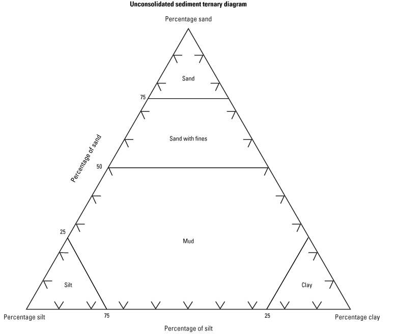
Sand-silt-clay ternary diagram for determining the detailed lithologic name of unconsolidated sediment intervals using grain size.
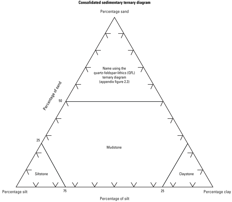
Sand-silt-clay ternary diagram for determining the detailed lithologic name of consolidated sediment intervals using grain size.
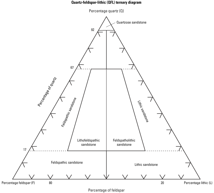
Quartz-feldspar-lithic ternary diagram for determining the detailed lithologic name of consolidated sediment intervals dominated by sand-sized grains using composition.
Appendix 3. Qualitative Terms for Describing Concentration and Degree in Drill Core
Appendix 4. Olivine and Plagioclase Concentration Charts

Diagram showing olivine concentration percentage by volume.

Diagram showing plagioclase concentration percentage by volume.

Diagram showing olivine and plagioclase concentration percentage by volume.
Appendix 5. Vesicle Concentration and Size Charts

Diagram showing vesicle concentration percentage and vesicle size.

Diagram showing vesicle concentration percentage and vesicle size.

Diagram showing vesicle concentration percentage and vesicle size.

Diagram showing vesicle concentration percentage and vesicle size.

Diagram showing vesicle concentration percentage and vesicle size.
Appendix 6. Fracture Frequency Charts
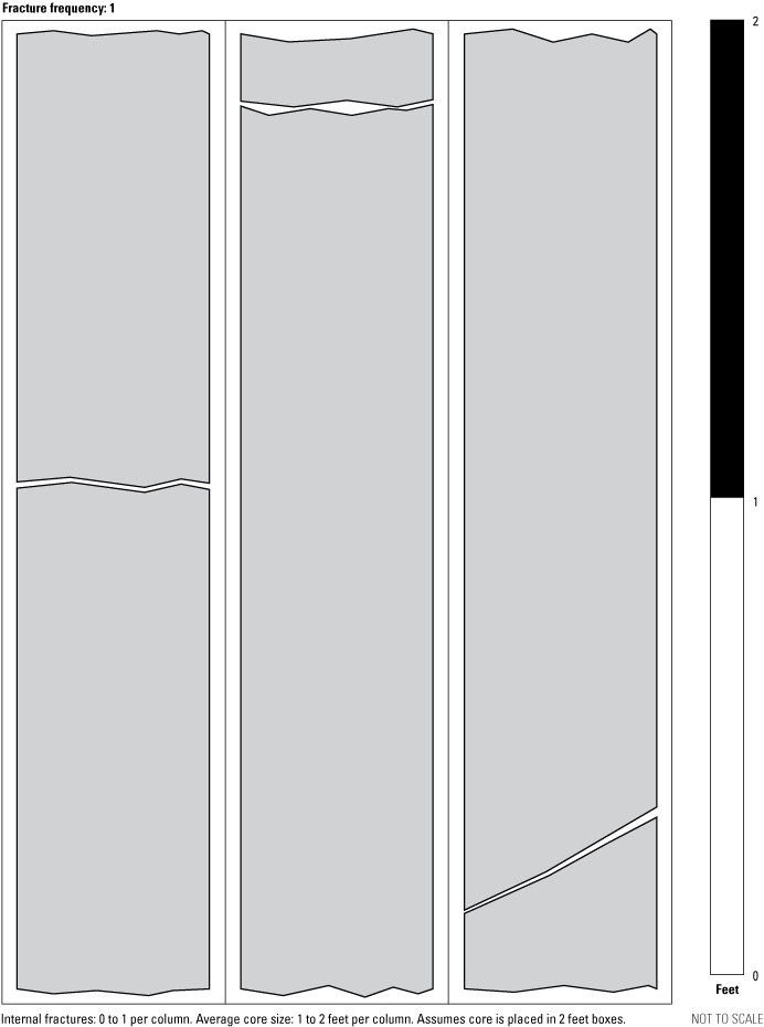
A diagram displaying core with fracture frequency 1.
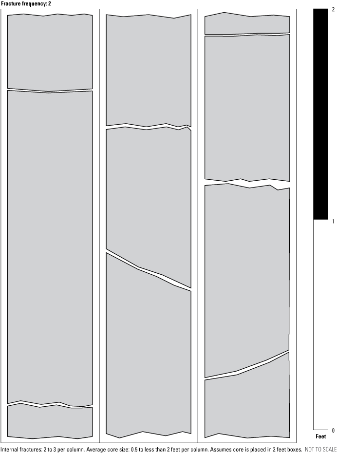
A diagram displaying core with fracture frequency 2.
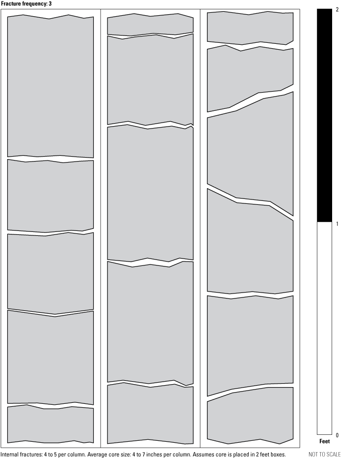
A diagram displaying core with fracture frequency 3.
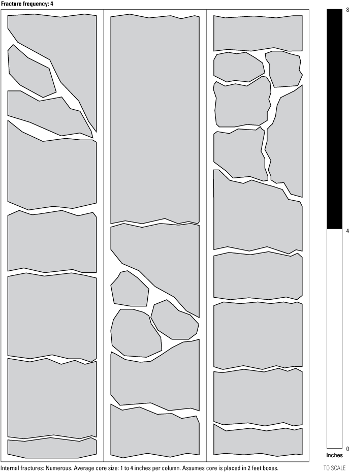
A diagram displaying core with fracture frequency 4.
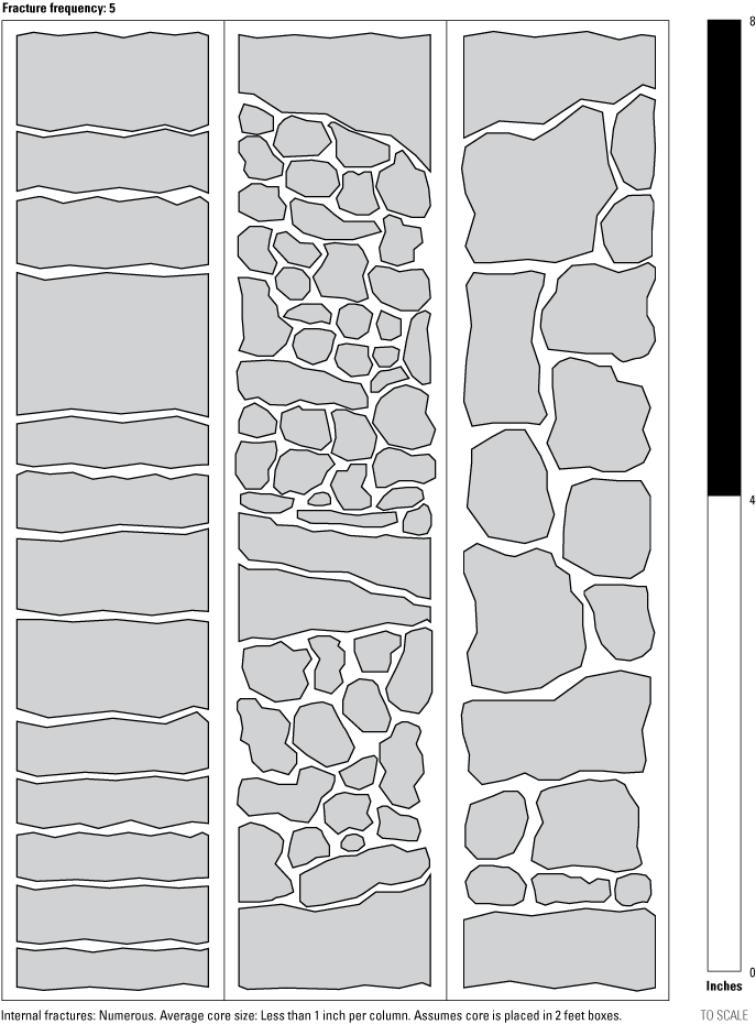
A diagram displaying core with fracture frequency 5.
Conversion Factors
U.S. customary units to International System of Units
Datums
Vertical coordinate information is referenced to the North American Vertical Datum of 1988 (NAVD 88).
Horizontal coordinate information is referenced to the North American Datum of 1983 (NAD 83).
Altitude, as used in this report, refers to distance above the vertical datum.
Disclaimers
Any use of trade, firm, or product names is for descriptive purposes only and does not imply endorsement by the U.S. Government.
Although this information product, for the most part, is in the public domain, it also may contain copyrighted materials as noted in the text. Permission to reproduce copyrighted items must be secured from the copyright owner.
Suggested Citation
Dietz, H., 2026, Standardized method for logging drill core at the Idaho National Laboratory, Idaho: U.S. Geological Survey Techniques and Methods, book 5, chapter E1, 54 p., https://doi.org/10.3133/tm5E1.
ISSN: 2328-7055 (online)
Study Area
| Publication type | Report |
|---|---|
| Publication Subtype | USGS Numbered Series |
| Title | Standardized method for logging drill core at the Idaho National Laboratory, Idaho |
| Series title | Techniques and Methods |
| Series number | 5-E1 |
| DOI | 10.3133/tm5E1 |
| Publication Date | April 21, 2026 |
| Year Published | 2026 |
| Language | English |
| Publisher | U.S. Geological Survey |
| Publisher location | Reston, VA |
| Contributing office(s) | Idaho Water Science Center |
| Description | Report: vi, 54 p.; 2 Appendixes |
| Country | United States |
| State | Idaho |
| Other Geospatial | Idaho National Laboratory |
| Online Only (Y/N) | Y |
| Additional Online Files (Y/N) | N |