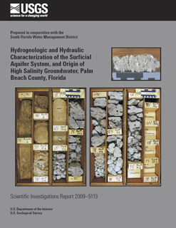
Scientific Investigations Report 2009–5113

Appendix II : Montages showing lithology, geophysical logs, geologic and hydrostratigraphic units, flow zones, and well construction for all wells with data availableIncluded in appendix 2 are log montages in WellCAD™ (WCL) file format showing data plots for 115 wells. Included are wells drilled prior to this study and four of the five wells drilled for this study. These wells are identified in table 1–8 of this report. In addition to all geophysical logs run and lithology, data included in the log montages and their column heading identifiers are geologic (FM) and hydrostratigraphic (HYD) units, if determined, flow zones (HYD-FZ), if determined, and well construction (CONST). Flow zones were determined by flow meter logs for four of the wells drilled in this study (PB-1804 though PB-1807) and two previously drilled wells (PB-1608 and PB-1761). The percentage of total flow during pumping is labeled for each flow zone in the HYD-FZ column. The lithology is shown by a lithologic symbols column (LITH) and a brief lithologic description column (Lithofacies). A more detailed lithologic description for five wells is provided by tables 1–2 through 1–6, including four of the wells drilled in this study and PB-1761. The WellCAD™ files in this appendix can be opened, viewed, and printed by installing the WellCAD Reader™ software included in this appendix. This software is non proprietary; however, the only modifications allowed that can be saved are scale changes. If a full version of WellCAD™ is available, these files may be opened, modified, and saved as usual. All of the plots in the appendix are saved in WellCAD™ at a vertical scale of 1 in. = 20 ft (except for PB-1761). Because of this scale, upon opening a file in WellCAD™, the full lithologic description may not be visible for all intervals. In particular, the lithologic descriptions for thin intervals (3 ft or less thick) do not appear. To view the lithologic description for all intervals, the vertical scale can be expanded in WellCAD Reader™, for example from 1 in. = 20 ft to 1 in. = 10 ft. Expansion of the vertical scale will also be required to view the digital borehole image included for PB-1807. |
Produced October 2009 For additional information contact: Appendix 2 is presented in WellCAD™ format (WCL) and requires the WellCAD™ reader to view it. The reader is provided on this CD or download it free of charge from the WellCAD™ website. |
Reese, R.S., and Wacker, M.A., 2009, Hydrogeologic and Hydraulic Characterization of the Surficial Aquifer System, and Origin of High Salinity Groundwater, Palm Beach County, Florida: U.S. Geological Survey Scientific Investigations Report 2009–5113, 83 p., (appendixes on CD).