Open-File Report 01-448
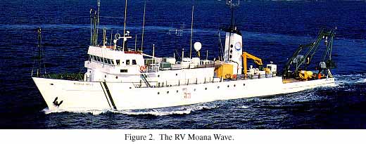
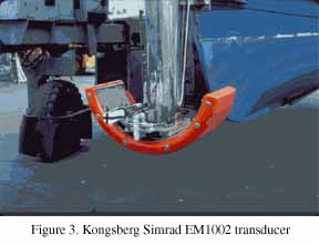
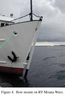
Cruise Report; RV Moana Wave cruise M1-01-GM; the bathymetry and acoustic backscatter of the mid shelf to upper slope off Panama City, Florida, northeastern Gulf of Mexico; September 3, through October 12, 2001, Panama City, FL to Panama City, FLThe Kongsberg Simrad EM1002 High-Resolution Multibeam Mapping System There are several different brands of high-resolution MBES systems that are appropriate for shallow-water surveys. After a review of the currently available systems, we chose to use the Kongsberg Simrad EM1002 system for this cruise because; (1) it is the latest generation of MBES with a frequency compatible with the depths we were interested in, (2) it is based on the highly successful EM1000 system, (3) it has the ability to map large areas at high speed without compromising data quality and, most importantly, (4) it has the ability to simultaneously produce high-resolution, calibrated acoustic-backscatter imagery. For the northwest Florida shelf survey, we used an EM1002 system owned and operated by C&C Technologies, Inc., Lafayette, LA, installed aboard the 220-ft RV Moana Wave (Figure 2, 28kb). An overview of high-resolution MBES systems in general can be found in Hughes-Clarke, et al. (1996). The Simrad EM1002 system operates at frequencies of 98 kHz (inner ±50° swath centered at nadir) and 93 kHz (the outer ±20°) from a semi-circular transducer (Figure 3, 17kb) mounted on a rigidly attached boom on the bow of the ship (Figure 4, 18kb). The system was designed to operate in several modes through a range of water depths from 5 to approximately 800-m. The shallow (ultrawide) mode, used to maximum depths of about 200 m, forms 111 receive apertures (used interchangeably with "beams") with a spacing of 2 distributed across track and 2 wide along track. The beam geometry generates a 150 swath that can cover as much as 7.4 times the water depth. The other two modes, wide mode, and deep mode, are for depths of greater than 200 m and were not used for the Northwest Florida shelf mapping. There are options within each mode for beam distribution (equiangular or equidistant) and pulse lengths (0.2, 0.7, and 2 ms). The specific options used for the Northwest Florida shelf survey are discussed in the data processing section below. Most conventional vertical-incidence echo sounders determine the time of arrival of the returned pulse (and thus the depth) by detecting the position of the sharp leading edge of the returned echo, a technique called amplitude detection. In multibeam sonars, where the angle of incidence increases to either side of the vertical for each consecutive receive beam, a returned echo loses its sharp leading edge and the depth determinations become inaccurate. To address this problem, the Kongsberg Simrad EM1002 MBES system uses an interferometric principle in which each receive aperture is split, through electronic beamforming, into "half beams" and the phase difference for each received signal for each aperture is calculated to provide a measure of the angle of arrival of the echo. The point at which the phase is zero (i.e., where the wavefront of the returned echo is normal to the receive-beam bore) is determined for each aperture and provides an accurate measure of the range to the seafloor. Both amplitude and phase detection are recorded for each aperture and the system software picks the "best" detection method for each aperture, based on a number of qualitycontrol measurements, and uses this method to calculate depth. The EM1002 also provides quantitative seafloor acoustic-backscatter data that can be displayed in a sidescan-sonar-like image (see Maps section below). The backscatter images can be used to gain insight into the spatial distribution of seafloor properties. A time series of echo amplitudes from each beam is recorded at 0.2- to 2.0-ms sampling rate, depending on the water depth. The echo amplitudes are sampled at a much faster rate than the projected aperture spacings and can be processed from beam-to-beam to produce a backscatter image with the theoretical resolution of the sampling interval (15 cm at 0.2 ms). The amplitude information can be placed in its geometrically correct position relative to the across-track profile because the angular direction of each range sample is known. The EM1002 software corrects the amplitude time series for gain changes, propagation losses, predicted beam patterns, and for the insonified area (with the simplifying assumptions of a flat seafloor and Lambertian scattering). Subsequent processing (see Processing section below) uses real seafloor slopes and applies empirically derived beam-pattern corrections to produce a quantitative estimate of seafloor backscatter across the swath. Ancillary Systems In addition to the multibeam sonar array, a MBES survey requires a careful integration of a number of ancillary systems. These include: (1) differentially corrected Global Positioning (DGPS) to aid an inertial navigation system (INS); (2) an accurate measure the heave, pitch, roll, and heading of the vessel, all to better than 0.01° and the transformation of these measurements to estimates of the motion of the transducer at the times of transmission and reception (motion sensor); (3) a method to precisely determine the sound-speed structure of the water column, using measurements of temperature and salinity with depth or directly measuring sound speed versus depth. Attitude Compensation The Northwest Florida shelf survey was navigated with a TSS Applanix POS/MV model 320 (version 2) INS inertial motion sensor (IMU) as well as dual Trimble model 4000 DGPS with a commercial Satloc satellite differential station. Spatial accuracy (positions) for the mapping is ±0.5 m. In addition, the POS/MV records vehicle motion (pitch, roll, heading, and heave) at 100 Hz with an accuracy of 0.02° for roll, pitch, and heading, and 5% of heave amplitude or 5 cm, which ever is greater. Sound-velocity profiles were calculated several times each day so that ray-tracing techniques could be used to correct refraction of the acoustic wave through the water column. A SeaBird model 19-02 CTD (conductivity and temperature vs depth) was used to measure temperature and salinity versus depth and sound speed vs depth was calculated from these measurements. An additional sound-velocity sensor is installed on the RV Moana Wave to continuously determine the speed of sound in water at the transducer depth. All the sound-speed data (SVP) are fed directly into the Simrad EM1002 processor for instantaneous beamforming and raytracing of the individual receive beams. Data Sources and Type Raw EM1002 data telegrams were acquired over a shipboard Ethernet network. The data stream is outlined in Table 1. In addition, a number of ancillary data sources were also acquired by C&C Technologies (Table 2). Table 1. Kongsberg Simrad EM1002 data stream.
Table 2. Ancillary data sources
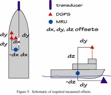
The accurate reduction of swath bathymetric data critically depends on a proper knowledge of the geometry and relative positions of the sonar transducer relative to the motion sensor, the ship, and the positioning-system antennae (Figure 5, 16kb). C&C Technologies, using standard surveying techniques, measured these values (Table 3) before the survey began. All values are measured relative to the transducer. EM1002 Operational Modes There are several operational modes available for the EM1002. The differences in the modes are a function of pulse length, beam spacing, and angular sector. The pulse length controls the amount of energy transmitted into the water column. The system can be operated in an "equiangular" (EA) mode in which the beams are spaced at equal angles apart, resulting in a non-linear (increasing spacing away from nadir) spacing of sonar footprints on the seafloor. The system can also be operated in an "equidistant" (EDBS) mode in which the beams are spaced such that the sonar footprints are equally spaced in the across-track profile. The EDBS geometry is achieved by generating variable beam-angular spacings. Although EDBS has advantages in data handling (i.e., provides even sounding density), there are two limitations. The beams in the 140° and 150° modes are spaced wider than their beam widths and results in incomplete coverage that produces a striping close to nadir. This problem disappears as the swath width closes to ~120°. However, the second limitation occurs because of attitude uncertainties and imperfect refraction models that can result in sounding errors that grow with angle from the vertical. Because these limitations render the outermost beams less reliable than for the EA mode, we used the EA mode. The Northwest Florida shelf survey was run in the EA mode and was operated with a 0.2 ms pulse length in waters less than 200 m deep and restricted swath widths of 350 to 500 m, depending on water depth. We restricted the swath width to about 4 times the water depth, with a 25-m overlap of adjacent swath so as to assure no data gap were generated by the large range in water depths. |
||||||||||
|
For more information, contact the PCMSC team.
Any use of trade, product, or firm names is for descriptive purposes only and does not imply endorsement by the U.S. Government. Suggested citation: Gardner, James V., Mayer, Larry A., Hughes Clarke, John E., Dartnell, Peter, Sulak, Kenneth J., 2001, Cruise Report; RV Moana Wave cruise M1-01-GM; the bathymetry and acoustic backscatter of the mid shelf to upper slope off Panama City, Florida, northeastern Gulf of Mexico; September 3, through October 12, 2001, Panama City, FL to Panama City, FL: U.S. Geological Survey Open-File Report 01-448, https://pubs.usgs.gov/of/2001/0448/. U.S. Department of the Interior U.S. Geological Survey |

![]() U.S. Department of the Interior |
U.S. Geological Survey
U.S. Department of the Interior |
U.S. Geological Survey
URL: http://pubsdata.usgs.gov/pubs/of/2001/0448/em1002.html
Page Contact Information: GS Pubs Web Contact
Page Last Modified: Wednesday, 07-Dec-2016 18:58:13 EST
