Data Series 921
| EquipmentThe high-resolution lidar data of the coastal zone at Fire Island, N.Y., were collected by the USACE-FRF team and are only one component of a larger dataset collected using the CLARIS platform. CLARIS is a vehicle-mounted system that integrates a terrestrial lidar scanner and X-band radar with precise motion and position information. For further information or questions regarding the CLARIS or for additional data not included in this report, please contact the USACE-FRF. Riegl VZ-1000Surface elevation data were captured using the Riegl VZ-1000 terrestrial laser scanner mounted on a 4x4 vehicle. This is the key piece of equipment used in this type of data acquisition. The terrestrial scanner images the topography by emitting a rapid series of infrared laser pulses across the beach and continuously measuring surface contact distance. Together with accurate scanner positional data, these measurements are used to create a 3-dimensional (3-D) point cloud of the surface. POS-LV 220Position data during the lidar scan were recorded using the Applanix POS-LV 220, a fully integrated system composed of an L1/L2 phase global positioning system (GPS) receiver, an inertial measurement unit (IMU), and a distance measuring instrument (DMI). The GPS data were collected through the two global navigation satellite system (GNSS) Zephyr* antennas and internal GPS receivers. The 3-D motion of the vehicle (yaw, pitch, roll) was recorded by the IMU, and the DMI measured the vehicle wheel rotations. All information from these sensors were then merged during post-processing to maintain sub-decimeter positional accuracy. Additionally, prior to beginning the survey the laser scanner was bore-sighted with respect to the IMU to account for subtle mounting differences between the two sensors, a process which can reduce data measurement error. 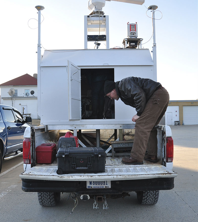 Figure 4. Various CLARIS instruments mounted atop the mobile CLARIS unit including 2 GNSS Zephyr antennas (outer masts), Riegl laser scanner (right of center), and marine radar antenna (top center). [larger version] *Any use of trade, firm, or product names is for descriptive purposes only and does not imply endorsement by the U.S. Government. |

![]() U.S. Department of the Interior |
U.S. Geological Survey
U.S. Department of the Interior |
U.S. Geological Survey
URL: http://pubsdata.usgs.gov/pubs/ds/0921/ds921_equipment.html
Page Contact Information: GS Pubs Web Contact
Page Last Modified: Monday, 28-Nov-2016 20:32:00 EST
