|
Multibeam Bathymetric and Backscatter
Maps of the Upper Hudson Shelf Valley and Adjacent Shelf, Offshore of New York
Data Collection and Processing
Add: In some of
the data, the faint regular parallel striping that is sometimes apparent
(for example the backscatter intensity data on Figures 6 and 7-10) reflects
the merging of data from adjacent swaths at the far range. Some of the data
taken during turns of the vessel have not been removed to provide maximum
data coverage.
The survey was conducted with a high-resolution multibeam shelf
|
|
|
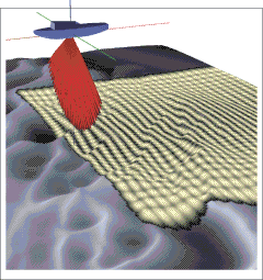
Figure 2. The Kongsberg Simrad
EM1000 high-resolution multibeam mapping system uses sound from an array transducers to measure water depth as well as sediment characteristics of the sea floor.
|
mapping system mounted aboard the Canadian Hydrographic Service vessel Frederick G. Creed, a 60-foot SWATH (Small Waterplane Twin Hull) ship that surveys at speeds of 15 knots. The Kongsberg Simrad EM1000 multibeam system (see Figure 2 at right) utilizes 60 electronically aimed beams spaced at intervals of 2.5° that can ensonify a strip of the sea floor up to 7.5 times the water depth. The footprint of the beam on the sea floor is approximately 10% of the water depth, or 3-5 meters in the survey region. The data presented were gridded at 6 m for the 1:25,000 maps (Fig. 5 and Figure 6) and at 3 m for the bathymetry and 2 m for the backscatter for the 1:12,500 maps (Fig. 7). Vertical resolution is approximately 1% of the water depth or better; thus for the water depths of 20-50 m in the survey area the resolution is better than 0.5 m.
Software developed by the Ocean Mapping Group, University of New Brunswick, was used to process and edit the bathymetric, backscatter, and navigation data (see World Wide Web URL http://www.omg.unb.ca/~jhc/SwathEd.html ). Tidal elevations measured at the NOAA Sandy Hook station (located at 40° 28.0'N and 74° 0.6' W) were used to adjust the data for the tidal fluctuations and reference them to mean low low water. The Mercator maps use a latitude of true scale at 40° N and are projected on the WGS84 ellipsoid.
The strength of the acoustic backscatter signal from the multibeam system is a measure of the reflectivity of the sea floor over the footprint of the acoustic beam. In general, high backscatter (light areas on maps) is characteristic of outcropping rock, gravel and coarse sands, and low backscatter (dark areas on maps) is characteristic of finer grained material. However, the backscatter intensity is not solely related to sediment texture; other observations such as bottom sampling and visual observations are needed to interpret the backscatter maps in terms of sea floor characteristics.
Some of the data taken while the vessel was turning at the end of lines has not been removed from the data set to provide maximum data coverage. In some of the data, faint regular striping appears. The striping runs parallel to the tracks that the ship steamed while collecting data. In the backscatter data, the striping often reflects poor data return at nadir (directly under the ship). Other striping in the backscatter is the result of differing reflection depending on the angle of incidence of sound. In the shaded relief bathymetric maps, the stiping reflects the merging of data from adjacent swaths at the far range.
Based on Butman, B., Danforth, W.W., Schwab, W.C., and Buchholtz ten Brink, M.B., 1998, Multibeam Bathymetric and Backscatter Maps of the Upper Hudson Shelf Valley and Adjacent Shelf, Offshore of New York: U.S. Geological Survey Open-File Report 98-616. |
Web page by: Donna Newman
[an error occurred while processing this directive]
|
|