
Gamma-ray Spectrometer System
Photos
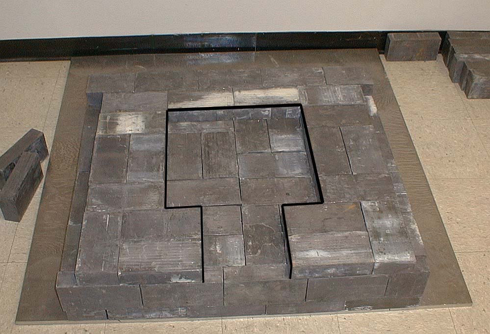 |
Figure 1: Castle is built on a 5/8" thick sheet of aluminum measuring 48" x 48", which is placed on the floor. This image shows the first three layers of lead bricks that forms the floor of lead castle. A fourth layer is added which has a 16" x 16" opening in its center, with an 8" wide opening for the sample holder. A heavy black line on image marks the inside upper edge of the fourth layer. A 3/8" thick sheet of aluminum is placed on top of the fourth layer. This sheet measures 32" x 32" and has a 16" x 16" square cut out of its center. This 16" square cutout lies directly above the 16" square opening of the fourth layer. (Click on photo to view larger image). |
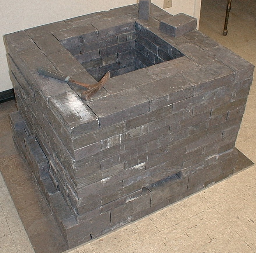 |
Figure 2: This image shows the nearly completed lead castle. The walls of the castle are 8" thick, with an opening 16" x 16" square and 24" deep which forms the interior of the castle. The photomultiplier tube and its support assembly are located inside. A 5/8" thick aluminum plate is then placed on top of this opening. The aluminum plate is 32" x 32" square and has a one inch hole drilled through the center to allow passage of the cable from the photomultiplier tube to the computer. Three additional layers of lead bricks are stacked on top of the plate to form the roof of the castle. The opening in the side of the castle for the sample holder is visible along the front face of the castle. (Click on photo to view larger image). |
 |
Figure 3: This image shows the completed lead castle with the rolling dolly in place. The 5/8" thick aluminum plate, as mentioned in the paragraph above, is visible in this image. To allow the passage of the cable from the photomultiplier tube to the PC, one inch holes were drilled through the top three layers of lead bricks. The lead bricks were drilled so that the cable zig-zags through the layers of lead bricks, thus preventing any direct path into the castle chamber. The dolly is made from a sheet of 3/8" thick aluminum about 16" square, with four heavy duty caster wheels bolted to the bottom. Lead bricks are placed on this dolly which is wheeled into place against the side of the castle to seal the opening. (Click on photo to view larger image). |
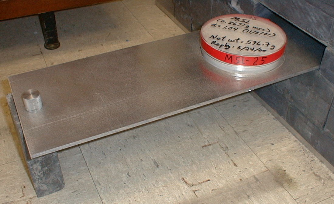 |
Figure 4: This image shows a clear plastic sample container (sealed with vinyl electrical tape) placed in the sample holder. After rolling the dolly away from the castle, the sample holder slides out so that samples can be changed. The sample holder is made from a sheet of 5/16" thick aluminum with a recessed hole to hold the sample container in place. Click here for further explanation about the design of the sample holder. (Click on photo to view larger image). |
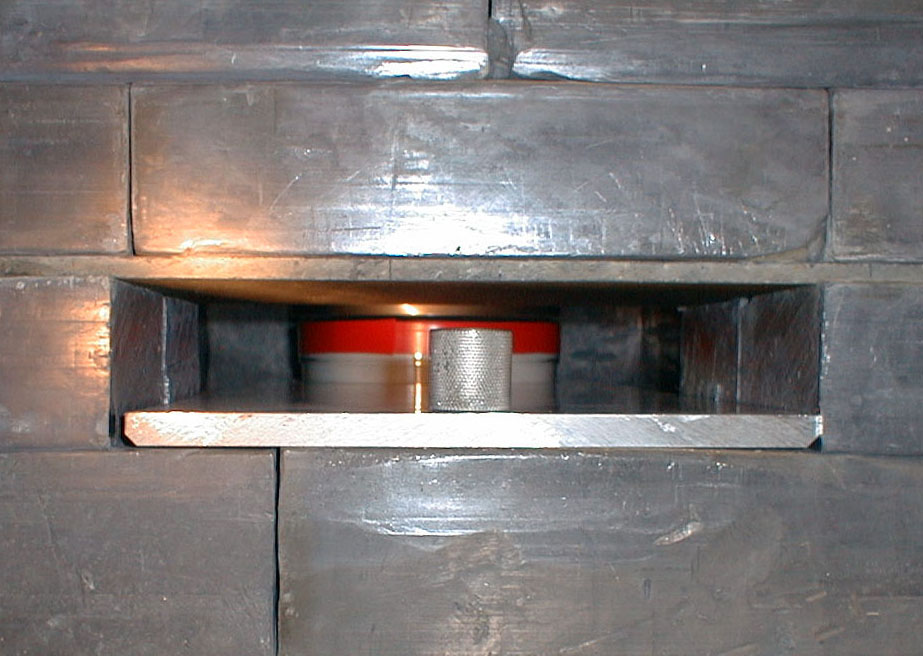 |
Figure 5: This image is a view looking into the opening in the side of the castle, which is sealed by lead bricks on the movable dolly. The aluminum sample holder with a plastic sample container is shown in place centered directly beneath the NaI detector, which is the silver-colored cylindrical object. The castle and support assemblies were designed so that the NaI detector sits about 1/8" above the sample container. The thin flat sheet above the opening is the 3/8" thick sheet of aluminum placed on top of the fourth layer of lead bricks as mentioned above in the description of Figure 1. (Click on photo to view larger image). |
Top || Introduction || Software || Hardware || Construction || References || Photos || Data
For more information about this report contact: Stephen
L. Snyder or Joseph S. Duval
[an error occurred while processing this directive]