Design of detector support assembly
Two aluminum plates were cut from 1/2" thick stock, one is 10" square and the second is 15.75" square. This second measurement is used so that it will fit inside the lead castle, which has an interior dimension of 16" square. Each of these plates has a 6.5" hole drilled through the center. The 10" square plate is the upper plate of the assembly. Four holes were drilled through the upper plate (one in each corner) to allow passage of 3/8" x 4" bolts. Nuts were then threaded onto each bolt, inserted through each hole in the upper plate and a second nut was threaded onto each bolt to hold the upper plate in place. This assembly then rests on top of the larger bottom plate, with the 6.5" holes aligned vertically to allow passage of the NaI detector assembly. The bottom plate rests on lead bricks standing on edge, 4" above the floor of the lead castle. The NaI detector assembly has a flange about 7" in diameter, allowing it to rest on the upper plate with the crystal housing extending through the holes in both aluminum plates. The bottom of the crystal housing rests a little more than 2" above the floor of the lead castle, allowing for placement of the sample container and sample holder directly beneath the detector. The height of the nuts and bolts is adjusted so that the clearance between the bottom of the detector and the sample container is about 1/8". Click on image below to view a detailed schematic diagram.
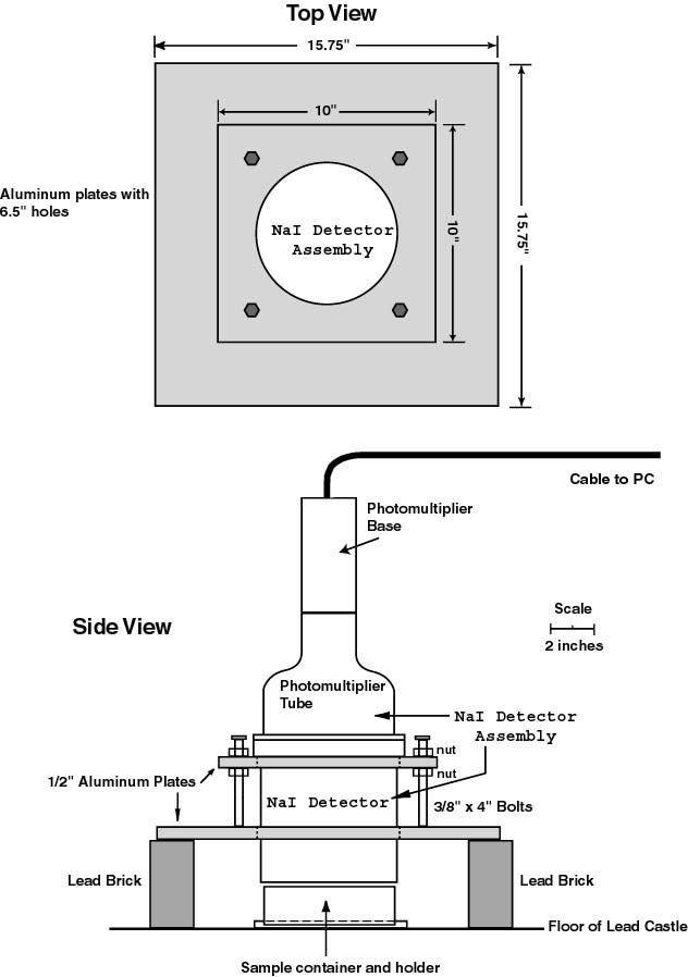
Schematic diagram of detector support assembly.
(Click on image to view larger image in new window)
Design of sample holder
The sample holder is made from a 5/16" thick sheet of aluminum, 22" long by 8" wide. A 6-1/8" (6.125") diameter hole is milled into the sheet to a depth of 3/16". This hole is centered 6" from one end and is shown in light blue in the figure below. To facilitate the changing of samples, the sample holder is designed to slide out of the castle. To accomplish this, an aluminum knob is screwed into the opposite end of the sample holder, about 1" from the end and centered along the edge. Click here to see photo (Fig. 4).
The sample containers (each one is about 6" in diameter and 1.5" high and made of clear plastic) are then placed in the recessed hole of the sample holder. The sample holder with sample container then slides into an opening in the side of the lead castle, placing the sample container directly beneath the NaI detector. Click here to see photo (Fig. 5). Lead bricks (for the detector support assembly) will prevent the sample holder from sliding any further. Click on image below for a more detailed schematic diagram.
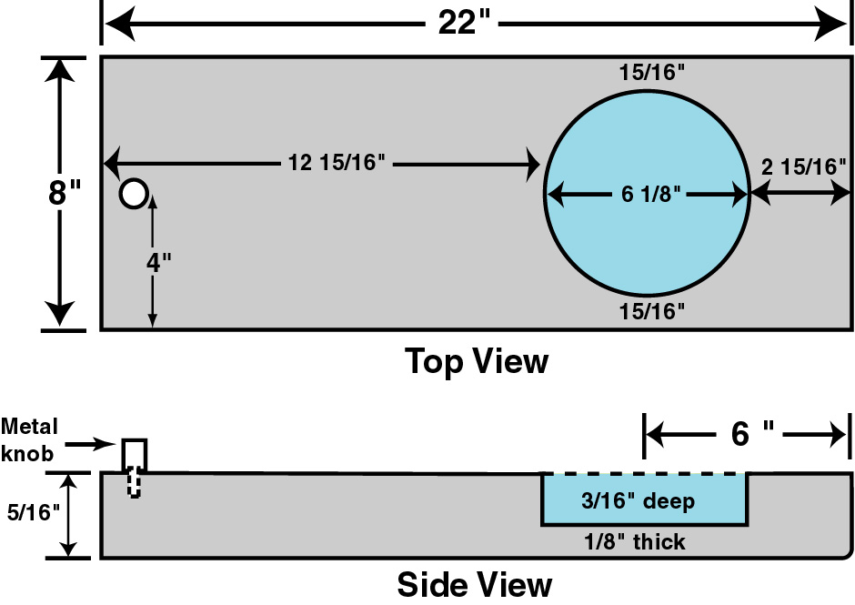
View of Sample Holder.
Side view shown cut-away (exaggerated vertically).
(Click on image to view more detailed schematic diagram in new window)
Layout of bricks of castle layers
(as viewed from above with front of castle at bottom of each image)
Click on an image below for a description of that layer. A new window will open.
| Bottom Layer of lead bricks
|
Second Layer of lead bricks
|
| Third Layer of lead bricks
|
Fourth Layer of lead bricks
|
| Alternating Odd Body Layers of lead bricks
|
Alternating Even Body Layers of lead bricks
|
| Bricks for Detector Support Assembly
|
Third Layer From Top of lead bricks
|
| Second Layer From Top of lead bricks
|
Top Layer of lead bricks
|
Notes:
The castle and dolly as described in this report is built using 480 8" x 4" x 2" lead bricks, 12 6" x 4" x 2" lead bricks and 12 4" x 4" x 2" lead bricks. The total weight of the lead bricks alone is about 12,700 lbs. (5760 Kg). Adding the aluminum plates for the castle and the detector support assembly plus the weight of the NaI(Tl) detector assembly brings the total weight to over 13,000 lbs. (5,900 Kg). When building a similar system, the total weight must be taken into account before deciding on a location for the entire assembly. A ground floor with a concrete slab is recommended.
Top || Introduction || Software || Hardware || Construction || References || Photos || Data
For more information about this report contact: Stephen
L. Snyder or Joseph S. Duval
[an error occurred while processing this directive]