U.S. Geological Survey Open-File Report 2009-1101
The Partition Intervalometer: A Programmable Underwater Timer for Marking Accumulated Sediment Profiles Collected in Anderson Sediment Traps: Development, Operation, Testing Procedures, and Field Results
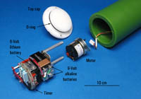
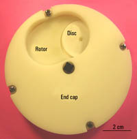
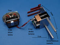
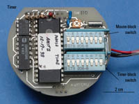
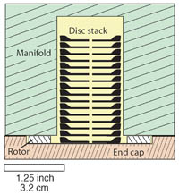
The programmable Partition Intervalometer releases disk-shaped markers into the sediment-trap funnel. The markers descend into the collection tube attached beneath the sediment trap. Eight Intervalometers were ultimately fabricated, modified, and tested by researchers at the USGS. Pressure CaseThe external pressure case is fabricated of cast Delrin tubular stock with a wall thickness of approximately 1.25 cm. The case is sealed at the top by a nylon cap with a radially sealed O-ring and by a similar O-ring assembly above the manifold. Mechanical OperationThe electronic components consist of a timer, battery packs, and drive motor that are arranged within a support frame inside the pressure case (fig. 6). A timer activates a 6-volt DC 1-revolution per minute gear motor, which initiates counterclockwise movement of a shaft-driven rotor. After the rotor rotates approximately 90°, the cutout portion captures a single disc from the supply manifold. The rotor and disc continue to move until the disc is dropped through the release hole of the magazine end cap (fig.7). When the rotor has completed a 360° rotation, it returns to the original starting position located slightly offset forward of the drop hole of the end cap. The rotor remains in place until the timer initiates the next programmed cycle. Power is supplied to the motor by a 6-volt lithium battery and to the timer by a 9-volt battery. The batteries may last for over one year if longer programmed time intervals are used. A support frame was fabricated by the USGS electronics group to connect the timer and battery assembly into a unified design array (fig. 8). This modification improves the stability, access, and servicing of the electronics components within the Intervalometer pressure housing. ProgrammingThe Intervalometer is programmed by removing the top cap and accessing the timer board at the top of the electronics package. Two 2x8-gang block switches are labeled “mouse” and “time” (fig. 9). The number 1 switch on the mouse block is set upwards to the position labeled “on,” and the remaining switches are set downward to the position labeled “off.” The time switches are moved to the position labeled “on” to the desired programmable time interval for the release of a disc from the Intervalometer (appendix 1). With the pressure-housing cap off, the user-defined program is initiated by passing a household magnet several times over the top of the timer and around the outside of the pressure case. The drive motor will commence operation, and one disc will drop as confirmation from the release hole of the end cap. It is advisable to reinitiate the program a second time by passing the magnet over the timer in a similar manner (a disc will likewise drop as verification) to ensure proper operation. The program is now established, the discs may be reloaded into the manifold chamber, and the cap may be resealed and gently screwed down. A test mode of short duration (10-minute drop cycle) may also be selected to allow the investigator to assess and observe the functional capability of the instrument during a maintenance operation like a battery change or a short duration test cycle. If all switches on both blocks are moved to the off position and switch 1 on the mouse block is moved to the on position, the program will be initiated as previously described, and a disc will be released every 10 minutes. The first disc may take up to 12 minutes to drop; however, the remaining discs will drop at the prescribed 10 minute intervals. Loading the Partitions into the ManifoldTwenty discs may be loaded into the magazine chamber by removing the magazine end cap (by loosening 4 screws), removing the rotor from the shaft, and placing the discs into the chamber oriented concave up (fig. 10). |

![]() U.S. Department of the Interior |
U.S. Geological Survey
U.S. Department of the Interior |
U.S. Geological Survey
URL: https://pubsdata.usgs.gov/pubs/of/2009/1101/html/operation.html
Page Contact Information: Contact USGS
Page Last Modified: Wednesday, 07-Dec-2016 21:55:00 EST