Data Series 982
|
Data AcquisitionNavigationLocation information associated with each GPR line was determined by post-processed differential correction using a base/rover setup. The field setup consisted of two (rover and base station) Ashtech ProFlex Global Navigation Satellite System (GNSS) receivers and antennas. The GNSS base and rover receivers recorded the raw full-carrier-phase positioning signals (L1/L2) from satellites, via Ashtech GNSS antenna, concurrently at 0.2 seconds (s) (5 Hertz [Hz]) intervals throughout the survey. The base station receiver was positioned on the National Geodetic Survey (NGS) published reference point NGS PID# BH1755 (Station ID: 8735180), located on the east side of the island, at the entrance to Fort Gaines (fig. 2). The vertical offset between the GNSS antenna and the NGS benchmark was 2.476 m. The rover GPS was mounted on a fixed frame above the GPR unit. The offset between the rover GNSS antenna (located on the GPR unit) and the ground was 1.915 m. Uncorrected positions were output from the rover GPS to the GPR as a National Marine Electronics Association (NMEA) GGA string at a 9600 baud rate. 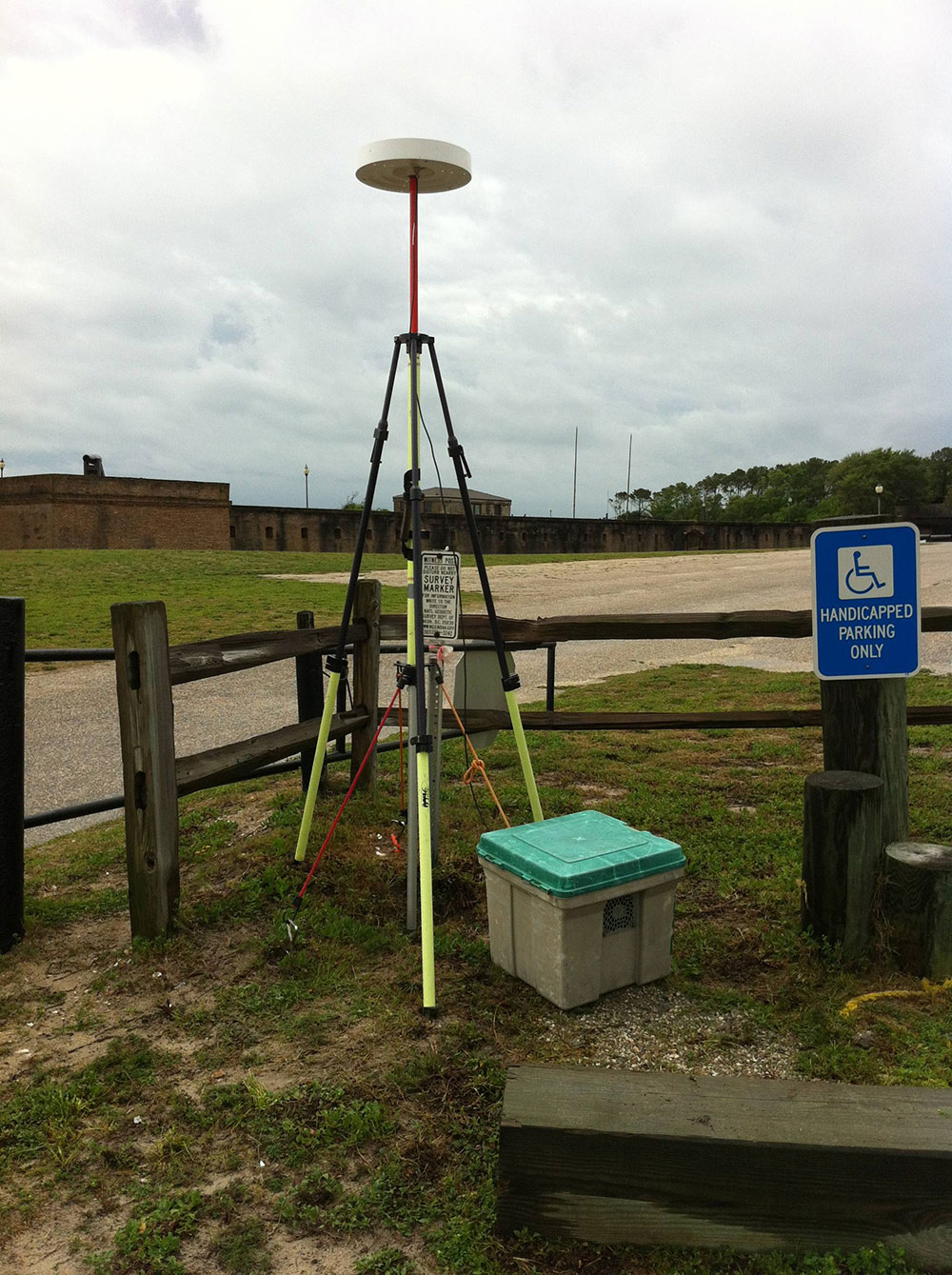 Figure 2. Photograph of Ashtech Differential Global Positioning System (DGPS) base station setup near the entrance of Fort Gaines, which is located on the eastern side of Dauphin Island, Alabama. Photograph by Nancy DeWitt (USGS). Ground Penetrating RadarA total of 65 GPR lines, representing a linear distance of approximately 40.23 km, were acquired during field activity 13BIM01. Data were collected, over various terrains, either on foot or towed at slow speeds (less than 10 miles per hour [mph]) behind a vehicle (fig. 3). The GPR data were collected with a Geophysical Survey Systems, Inc. (GSSI) TerraSIRch SIR System-3000. This system collects single channel GPR and contains a digital control unit (model DC-3000), 10.8-volt lithium-ion rechargeable battery (which allows up to 3 hours of survey time), a 200 megahertz (MHz) antenna and cables, and a 16-inch survey wheel (model 620) that acquired 417 ticks per meter. Additional equipment used in conjunction with the GSSI included an external [puck] GPS Acumen data logger, support poles with associated hardware (for the GPS system), harness, and tow strap. The GPR system’s internal memory capacity is roughly 1 gigabyte (GB) of data; however, to ensure there would be no data loss, files were recorded to both the internal memory and a SanDisk CompactFlash memory card. Acquisition settings for the subsurface profiles were set to 64 scans per second, 20 scans per unit (m), 1,024 samples per second, 16 bits per sample, dielectric constant = 15, range = 200 nanoseconds (ns), and auto gain. Due to the homogeneous nature of Dauphin Island’s near surface deposits, the preceding settings were applicable for most lines; however, adjustments were made when changes to the terrain or subsurface geology warranted such modifications. An Infinite Impulse Response (IIR) filter was used (Lowpass = 600 MHz and Highpass = 50 MHz) to downplay external interference, thus increasing the signal and decreasing the amount of background noise. Each day, prior to collecting any data, the distance setting was used to manually calibrate the survey wheel for the terrain by laying out a 10-m-long measured line on the survey surface, which varied between asphalt (fig. 3), sandy dune slopes (fig. 4), and grass. Calibration steps consisted of (1) entering the calibration distance, (2) positioning the antenna at the start of the calibration line, ensuring that the same part of the antenna positioned at the line start also ended at the terminus of survey line, and (3) pulling the wheel the predetermined distance. These steps were repeated until a satisfactory average value was obtained, at which time the value was saved into the system. Data were acquired using RADAN 7 proprietary software [in TerraSIRch mode] and saved in Radan’s DZT (.dzt) format. 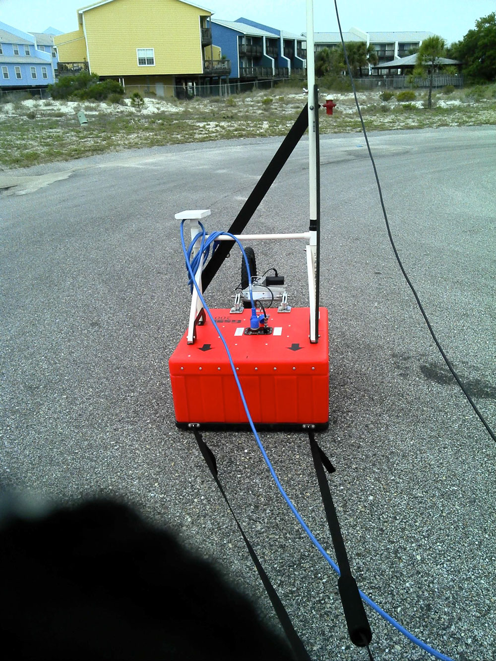 Figure 3. Photograph of Geophysical Survey Systems, Inc. (GSSI) ground penetrating radar system being towed behind a vehicle, during field activity 13BIM01. Photograph by Christopher G. Smith (USGS). 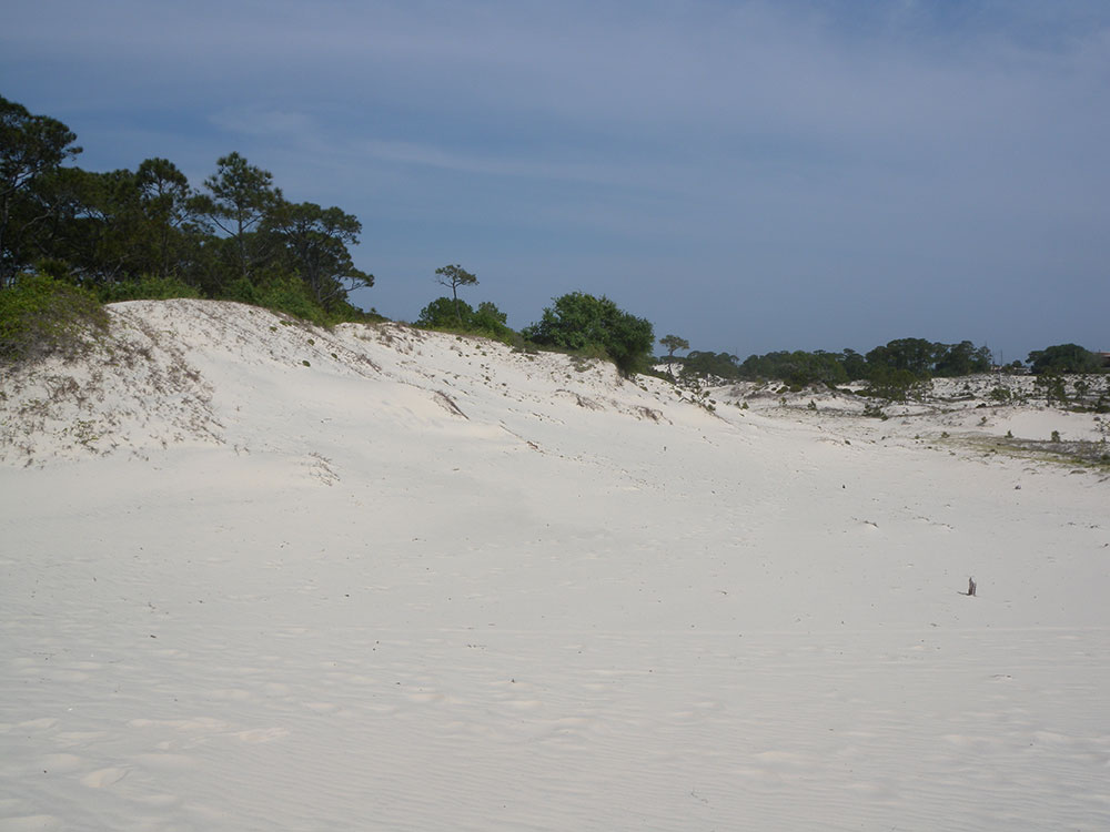 Figure 4. Photograph of sandy dunes encountered during field activity 13BIM01 GPR data acquisition. Photograph by Christopher Sherwood (USGS). |

![]() U.S. Department of the Interior |
U.S. Geological Survey
U.S. Department of the Interior |
U.S. Geological Survey
URL: http://pubsdata.usgs.gov/pubs/ds/0982/ds982_data-acquisition.html
Page Contact Information: GS Pubs Web Contact
Page Last Modified: Monday, 28-Nov-2016 20:45:27 EST
