Skip past header information
USGS - science for a changing world

U.S. Geological Survey Open-File Report 2011-1156

Carolinas Coastal Change Processes Project Data Report for Observations near Diamond Shoals, North Carolina, January-May 2009
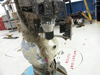
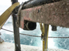
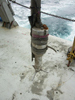
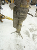
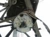
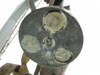
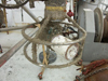
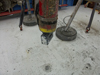
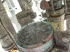
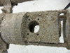
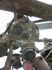
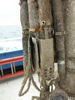
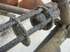
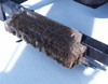
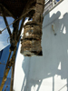
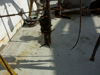
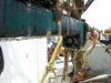
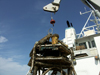
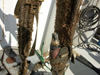
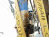
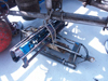
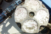
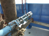
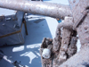

Biological Fouling

Skip past contents information

Bio-fouling

Biological fouling (bio-foudling) often degrades acoustic and optical data after several months of instrument deployment. Organisms grow on the instrument transducers and gradually block acoustical pulses and light transmission, which results in a gradual drift of the beam attenuation. Care has been exercised to remove data that have been affected by bio-fouling.

Biofouling Photos:

Site
North Flobee
Figure 18.
Optical Backscatter Sensor (OBS) with anti-fouling wiper.
Figure 19.
Figure 19. Transmissometer with copper anti-fouling tape
Figure 20.
Figure 20.Bio-fouling of an Acoustic Doppler Velocimeter (ADV).

North Flobee (continued)

Figure 21.
Figure 21.
Bio-fouling of an Acoustic Doppler Velocimeter (ADV).
Figure 22.
Figure 22.
Bio-fouling of a Pulse-Coherent Acoustic Doppler Profiler (PCADP).
Figure 23. site1 first deployment.
Figure 23.Bio-fouling of an Acoustic Backscatter Sensor (ABS).
North Minipod
Figure 24.
Sonar with anti-fouling zinc paste.
Figure 25.
Figure 25.Fanbeam with anti-fouling zinc paste.
Figure 26.
Figure 26. Bio-fouling of a Camera case.
North Minipod (continued)
Figure 27.
Bio-fouling of a Laser In Situ Suspended Scattering and Transmissometry (LISST).
Figure 28.
Figure 28. Aquadopp and tripod fouling
Figure 29.
Figure 29.Bio-fouling of a SEACAT and pump.
North Minipod (continued) Figure 30.
Figure 30. Bio-fouling of a Transmissometer.
North Surface Buoy Figure 31.
Figure 31. Bio-fouling of a MicroCAT.
South Flobee
Figure 32.
Acoustic Backscatter Sensor (ABS) with anti-fouling zinc paste.
Figure 33.
Figure 33.Pulse-Coherent Acoustic Doppler Profiler (PCADCP) with anti-fouling zinc paste.
Figure 34.
Figure 34.Bio-fouling of an Acoustic Doppler Velocimeter (ADV).
South Flobee (continued)
Figure 35.
Transmissometer with copper anti-fouling tape
Figure 36.
Figure 36.
Bio-fouling of an Acoustic Doppler Current Profiler (ADCP) and tripod.
Figure 37.
Figure 37.Bio-fouling of an Optical Backscatter Sensor (OBS).
South Flobee (continued) Figure 38.
Figure 38
Bio-fouling of an Optical Backscatter Sensor (OBS).
South Surface Buoy

Figure 39.
Figure 39.
Bio-fouling of a SEACAT and Transmissometer.

Tip Micropod
Figure 40.
Acoustic Doppler Current Profiler (ADCP) with anti-fouling zinc paste.
Figure 41.
Figure 41.
Bio-fouling of a Transmissometer.
Figure 42.
Figure 42.Bio-fouling of a SEACAT.
Skip USGS links group

Accessibility FOIA Privacy Policies and Notices

Take Pride in America logo USAGov logo U.S. Department of the Interior | U.S. Geological Survey
End of USGS links group