U.S. Geological Survey Open-File Report 2012-1219
Carolinas Coastal Change Processes Project data report for nearshore observations at Cape Hatteras, North Carolina, February 2010
A variety of instruments from many manufacturers were used to measure water flow, sea level, temperature, wave characteristics, near-bottom turbulence, and suspended-sediment concentrations. These instruments were deployed from February 2, 2010, through March 20, 2010, on a variety of platforms, as described on the Field Program page. Data were recorded at sampling schemes specific to each instrument. The details of the sampling strategy for each instrument are provided on the Mooring Identification and Field Mooring Log page. After recovery, data were downloaded and processed using established techniques (see the Data Processing page) to convert data from proprietary format to scientific units. Provided below are brief details taken from Montgomery and others (2008) for the instruments utilized during this specific study. A complete description of all equipment and data-processing methods are provided in Montgomery and others (2008). Instrument descriptions for the lighthouse camera system, Wellen radar (WERA), nearshore surveys, and benthic unattended generator (BUG) are not included in this report. For inquiries regarding the lighthouse camera system, WERA, nearshore surveys, and BUG please see the contact information on the Digital Data Files page. Jump To Teledyne RD Instruments Acoustic Doppler Current ProfilerNortek Aquadopp Acoustic Profiler Sontek Triton Acoustic Doppler Velocimeter Acoustic Backscatter Sensor Teledyne RD Instruments Acoustic Doppler Current ProfilerThe Teledyne-RD Instruments (T-RDI) acoustic Doppler current profiler (ADCP) (http://www.rdinstruments.com/) measures the speed and direction of water flow using the Doppler principle. Acoustic pulses are transmitted by the ADCP's transducer assembly along two pairs of orthogonal beams (four beams total). Scatterers in the water column, such as small particles and plankton traveling with the water flow, reflect the acoustic pulses. The ADCP transducer assembly receives the reflected pulses and, using the Doppler effect and basic trigonometry, converts the pulses into eastward, northward, and vertical components of water flow. When installed with waves acquisition firmware, T-RDI ADCPs record three types of data from which wave properties may be computed: pressure, range to surface along each orthogonal beam (that is, water level), and orbital velocities of the surface waves taken from three bins nearest the surface in each of the four beams. It is possible to estimate nondirectional wave energy spectra, and thus wave height and period, from any of the three data types. To calculate the directional distribution of wave energy, T-RDI software uses an array of orbital velocities measured near the surface. References for the principles of operation for the Doppler water-flow measurement technique may be found at http://www.rdinstruments.com/rdi_library.html. The Teledyne RD Instruments' primer on ADCP wave measurements may be found at http://www.rdinstruments.com/waves.html. Nortek Aquadopp Acoustic Profiler
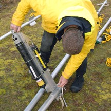
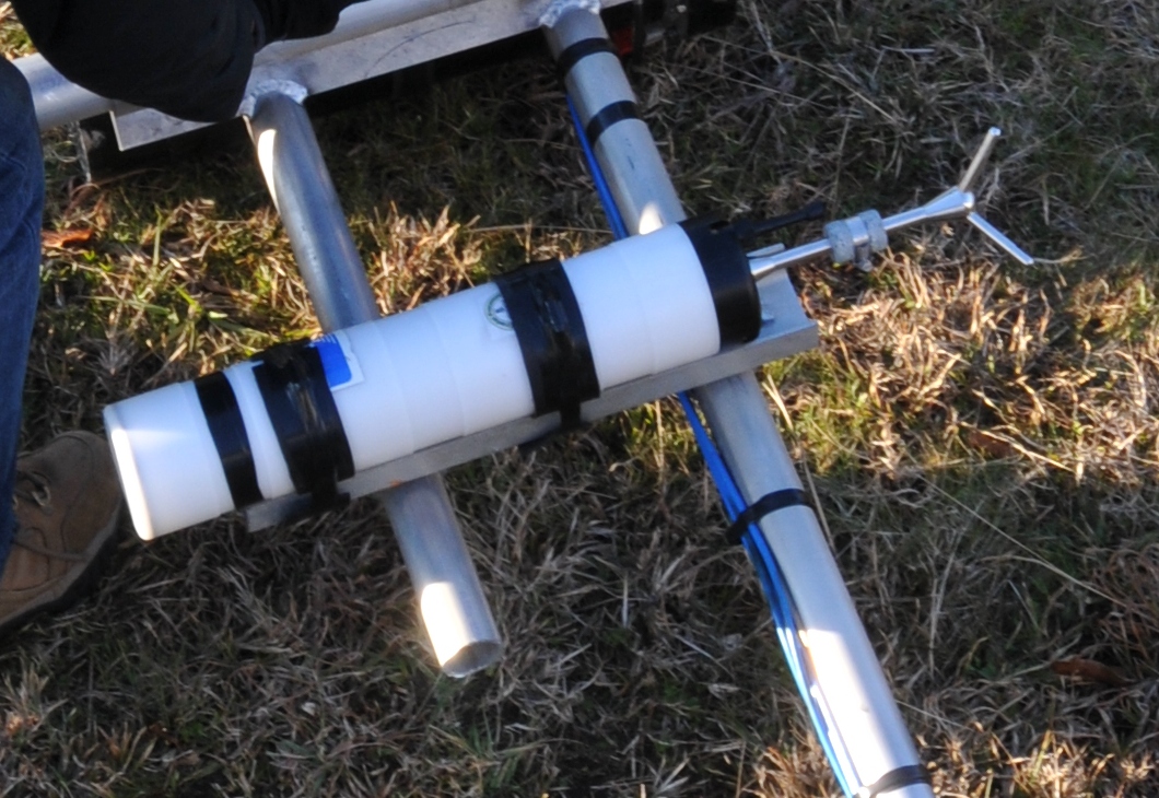
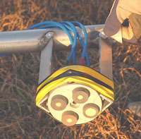
The Nortek Aquadopp acoustic profiler measures water flow and wave characteristics. Like a T-RDI ADCP, the Aquadopp measures water flow using the Doppler principle (fig. 3). For wave measurements, the Aquadopp measures wave pressure and near-bed velocities. The PUV (pressure and horizontal orbital velocity components U and V) method is used to estimate wave parameters. The pressure signal is used to estimate wave height; the measurements of the waves' orbital velocities provide an estimate of the wave direction. Unlike an ADCP, the Aquadopp has only three acoustic beams that can be arranged in any of five configurations. Each configuration is optimized for certain applications. For additional information on the Nortek Aquadopp acoustic profiler, refer to http://www.nortekusa.com/ . The Aquadopp is a monostatic instrument. Sontek Triton Acoustic Doppler VelocimeterThe Sontek Triton acoustic Doppler velocimeter (ADV) is a single-point, Doppler current meter designed specifically for low-power measurements in shallow water (fig. 14). The Triton-ADV system measures current speed and direction at a single point in a sampling volume of approximately 2 cubic centimeters using the Doppler principle and the difference between signal returns at the three receivers. The instrument can sample both currents and pressure at high frequencies in multiple sampling schemes, and store the complete raw data set, allowing for the calculation of wave and turbulence parameters. For additional information on the Sontek Triton-ADV, refer to http://www.sontek.com/ . Acoustic Backscatter SensorThe acoustic backscatter sensor (ABS) is a multifrequency acoustic backscatter instrument that logs profiles of backscatter intensity from sound pulses delivered at different frequencies (fig. 15). Use of multiple frequencies allows interpretation of the backscatter data according to different sediment-size ranges. The unit records bursts of backscatter intensity, allowing high-resolution measurements in time and space. This system is monostatic, and the gain applied to the return signal is linear in order to provide more consistent return over the length of the profile than ADCP-received signal gains, which are designed to maximize the range of the instrument. The ABS instrument emits pulses of high-frequency sound from up to four transducers, which may operate at different frequencies. These pulses are scattered by suspended sediments in the water column. The quantity of sound scattered back to the sensor (backscatter) can be combined with instrument calibration coefficients to determine vertical profiles of suspended-sediment concentrations. |

![]() U.S. Department of the Interior |
U.S. Geological Survey
U.S. Department of the Interior |
U.S. Geological Survey
URL: http://pubsdata.usgs.gov/pubs/of/2012/1219/instruments.html
Page Contact Information: GS Pubs Web Contact
Page Last Modified: Monday, 26-Aug-2013 12:17:13 EDT