 |
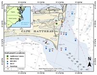
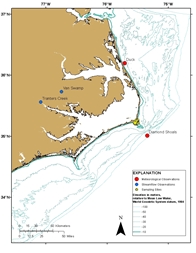
Figure 1. Location map for Cape Hatteras, North Carolina. Markers are placed to identify the nearshore (starting with “N”), offshore (starting with “O”), lighthouse, and Wellen radar (WERA) sites. Locations for Aquadopps (current profiler utilizing Doppler technology), acoustic backscatter sensor (ABS),acoustic Doppler velocimeter (ADV), and acoustic Doppler current profilers (ADCP) are identified.
|
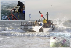 |
Figure 2. A lighter amphibious resupply cargo watercraft used as a dive platform (center). Photograph by Don Bowers. U.S. Geological Survey (USGS) divers deploying (upper left) and retrieving (lower right) instruments. Photography by Dann Blackwood, USGS. |
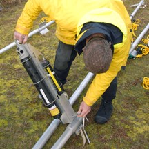 |
Figure 3. A U.S. Geological Survey employee mounting a cantilever arm holding an aquadopp (current profiler using Doppler technology) and pinger onto a jet pipe. Photograph by Don Bowers. |
 |
Figure 4. An acoustic Doppler current profiler (ADCP) pole mount with an ADCP attached. Photograph by Don Bowers. |
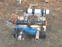 |
Figure 5. Pole mount for the acoustic Doppler velocimeter Triton, acoustic backscatter sensor and associated pressure cases. Photograph by Don Bowers. |
 |
Figure 6. A trawl-resistant bottom mount containing an acoustic Doppler current profiler. Photograph by the Woods Hole Group. |
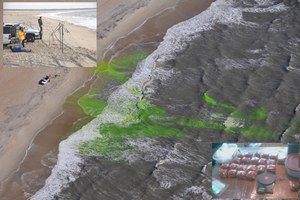 |
Figure 7. Aerial photograph of Uranine dye release in the surf zone (center). The slingshot used to launch dye packets into the surf (upper left); dye packets are displayed (lower right). Aerial photograph by Dann Blackwood, U.S. Geological Survey. Slingshot photograph by Don Bowers. |
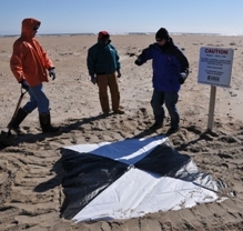 |
Figure 8. Aerial target used during the Cape Hatteras dye-release study. Photograph by Dann Blackwood, U.S.Geological Survey. |
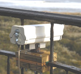 |
Figure 9. Video camera system mounted on the railing at the top of the Cape Hatteras Lighthouse. Photograph by Don Bowers. |
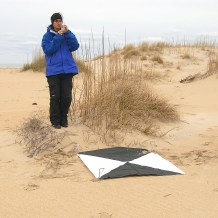 |
Figure 10. Aerial target used for the lighthouse camera rectification. Photograph by Don Bowers. |
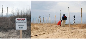 |
Figure 11. Wellen radar system transmit (left) and receive (right) antenna arrays. Photography by Don Bowers. |
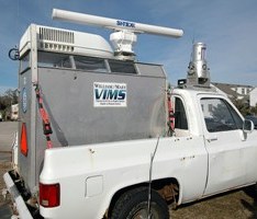 |
Figure 12. The truck equipped with a coastal light detection and ranging system and an X-band radar imaging system. Photograph by Don Bowers. |
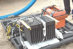 |
Figure 13. The benthic unattended generator deployed by the Naval Research Laboratory. Photograph by Don Bowers. |
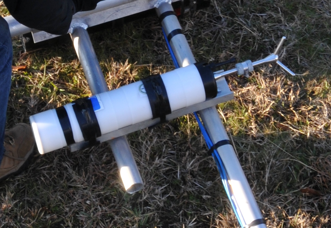 |
Figure 14. An acoustic Doppler velocimeter. Photograph by Don Bowers. |
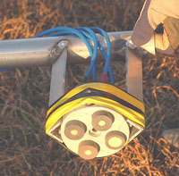 |
Figure 15. Sensors for an acoustic backscatter sensor. Photograph by Don Bowers. |
|
Figure 16. Map showing locations of supporting observations. |

