U.S. Geological Survey Open-File Report 2011-1113
Summary of Oceanographic and Water-Quality Measurements in West Falmouth Harbor and Buzzards Bay, Massachusetts, 2009-2010
| Click on figures for larger images |
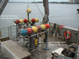 |
| Figure 4. Tripods prior to deployment in Buzzards Bay (moorings 859, 860). |
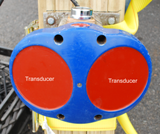 |
| Figure 5. Side-looking ADCP (SL-ADCP) before deployment on the rudder of the T/S Kennedy (mooring 861). Two acoustic transducers allow for estimation of two-dimensional horizontal velocities; three- and four-transducer ADCPs estimate two-dimensional horizontal velocities and vertical velocities. |
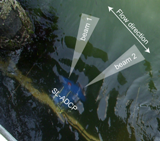 |
| Figure 6. Position and schematic of beam
spread for the SL-ADCP deployed on pier, facing entrance channel to West
Falmouth Harbor (mooring 901). Actual beams traveled over 20 meters into the
channel before interference with the channel bed and water surface (due to beam
vertical spreading).
|
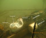 |
| Figure 7. Upward-looking Nortek Aquadopp and
Sea-Bird 39 PT sensor deployed on the seabed (moorings 882, 885, 887). White
paste on transducers is zinc oxide, used to reduce biological growth, which
interferes with signal transmission.
|
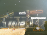 |
| Figure 8. Satlantic ISUS nitrate sensor and
YSI 6920 multiparameter sonde deployed on floating dock at 0.12 meters below
surface (mooring 883).
|
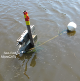 |
| Figure 9. Sea-Bird MicroCATs deployed on a vertical tower array (mooring 884). Three sensors were mounted on this array at 0.33 meters above bottom (not visible), 0.55 meters above bottom, and 0.77 meters above bottom. |
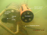 |
| Figure 10. Aanderaa RCM9 with optical
dissolved oxygen (DO) probe and YSI 6920 multiparameter sonde, deployed on the
seabed using a pedestal mount (mooring 886) 0.3 meters above bottom. Mooring
888 used a similar mount, with only a YSI multiparameter sonde.
|
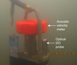 |
| Figure 11. Aanderaa RCM9 with acoustic velocity meter (Doppler Current Sensor; DCS) and optical dissolved oxygen (DO) probe mounted on seabed (mooring 900). |
|
All equipment used by the USGS Woods Hole Coastal and Marine Science Center Sediment Transport Group is described in detail by Montgomery and others (2007) and provides full equipment specifications and data processing protocols. Autonomous instruments, with self-contained power and memory storage, were deployed at multiple sites in Buzzards Bay and West Falmouth Harbor. These instruments were deployed to measure water temperature, salinity, velocity, pressure (depth), and water-quality parameters such as nitrate and chlorophyll-a. All instruments remained in place for the duration of the studies, except for water-quality equpiment, which was serviced weekly and returned to the fixed mounts. Instruments were programmed to sample in intervals ranging from 5 minutes (min) to 15 min, depending on the battery life and memory capacity. Deployment-specific details are given here; instrument specifications can be found at each manufacturer's Web site. Mooring logs detail the instrument serial numbers and data files. RD
Instruments (RDI) Acoustic Doppler Current Profiler (ADCP)
The RDI ADCP (www.rdinstruments.com) measures the speed and direction of water flow using Doppler principles. Acoustic pulses are transmitted by the ADCP transducer assembly along one or two pairs of orthogonal beams (for side-looking and upward-looking models, respectively). Scatterers in the water column, such as small particles and plankton traveling with the water flow, reflect the acoustic pulses. The transducer assembly receives the reflected pulses and, using the Doppler Effect and basic trigonometry, converts the pulses into eastward, northward, and vertical components of water flow (two-beam side-looking units can only resolve eastward and northward components). References for the principles of operation for the Doppler water flow measurement technique may be found at http://www.rdinstruments.com/rdi_library.html. Upward-looking 1,200 and 600 kilohertz (kHz) ADCPs were deployed on tripods at moorings 859 and 860, respectively, during the 2009 campaign (fig. 4). The ADCPs sampled in 3-min bursts every 10 min, in 1-meter (m) vertical bins, with the first bin located 2.31 m above bottom. A side-looking RDI ChannelMaster 600 kHz unit was deployed at moorings 861 and 901 during the 2009 campaign (fig. 5, fig. 6). At mooring 901, the unit was deployed on the Chapoquoit Association pier, at the entrance of West Falmouth Harbor. The ADCP was mounted on a 2 x 12 plank secured to the pier’s vertical pilings, at a mean depth of 0.85 m below the water surface. The ADCP was aimed in a cross-channel direction, collecting two-dimensional (east and north) velocity data in 0.5 m horizontal bins every 15 min in 1-min bursts. The velocity components were rotated to give an along-path velocity aligned with the channel. The center of the first bin was located 1.73 m from the ADCP, and the acoustic beams impinged on the surface and bed (due to beam spreading) approximately 20 m from the ADCP, depending on water level. At mooring 861, the unit was deployed on the fixed rudder of the T/S Kennedy on the western end of the Cape Cod Canal, at the Massachusetts Maritime Academy. The ADCP was mounted on a custom-designed wooden frame that was secured to the rudder using straps. Due to the vessel's buoyancy, the unit maintained a depth of 4 m below the surface. The ADCP was aimed in a cross-channel direction, collecting two-dimensional (east and north) velocity data in 1-m bins every 15 min in 1-min bursts. The velocity components were rotated to give an along-path velocity aligned with the channel. The center of the first bin was located 1.73 m from the ADCP, and the acoustic beams impinged on the surface and bed (due to beam spreading) approximately 40 m from the ADCP, depending on water level. WET Labs C-Star Transmissometer The WET Labs C-Star transmissometer (http://www.wetlabs.com/products/cstar/cstar.htm ) measures the percentage of light transmitted along a fixed path. This sensor uses light from a red Light Emitting Diode (LED) (650-nm wavelength), over a 25 centimeter path length. The measurements give an estimate of turbidity in the path of the instrument. A WET Labs C-Star transmissometer was deployed on the tripod at mooring 859 (fig. 4) during the 2009 campaign to estimate turbidity. The unit sampled every 5 min. Nortek
Aquadopp Acoustic Profiler (AQD)
The Nortek Aquadopp (www.nortek-as.com) measures water velocity and pressure (fig. 7). Similar to an ADCP, the Aquadopp measures water flow using Doppler principles. The instrument measures the Doppler shift that occurs when three acoustic beams reflect from scatterers that are carried by the water. Because Doppler shift is proportional to the component of water flow along the beam, trigonometry can be used to convert the returned signal into eastward, northward, and vertical components of water flow. Upward-looking 1,000 kHz Nortek Aquadopps were deployed during the 2010 campaign at moorings 882, 885, and 887 on aluminum I-frames (fig. 7). The instrument recorded 3-min averages of water flow every 5 min in 0.5-m bins. The first bin was located 0.7 m above the bottom. Due to shallow water depths at mooring 882 (Mashapaquit Creek), only one bin was usable at certain times. Sea-Bird SBE39 The Sea-Bird SBE39 (www.seabird.com) is a pressure and temperature (PT) sensor (fig. 7). The sensor has internal batteries and memory, and operates autonomously. Sea-Bird SBE39 pressure/temperature (PT) sensors were mounted alongside all Nortek Aquadopps to provide a separate measure of pressure and water level (fig. 7). The instruments sampled every 5 min. Satlantic ISUS The Satlantic ISUS (In-Situ Ultraviolet Spectrophotometer) sensor (www.satlantic.com) uses ultraviolet absorption principles to measure the concentration of nitrate (NO3) in water (fig. 8). The ISUS reports the full absorption spectrum, and can operate autonomously with an external battery housing and internal data logger. The ISUS was deployed at mooring 883, 0.12 meter below surface on a floating dock (fig. 8), to estimate nitrate concentration. Power was supplied by an external 12-volt battery mounted on the dock. The unit sampled at 1 hertz (Hz) for 30 seconds (s) every 5 min. The ISUS recorded a "dark" frame after every 10 regular samples to provide a baseline zero measurement with a closed shutter. YSI 6-series
Multiparameter Sonde
The YSI 6-series multiparameter sonde (www.ysi.com) is an autonomous water-quality sensor that can measure a variety of parameters with interchangeable probes (fig. 8; fig. 10). For these studies, sondes were equipped with conductivity, temperature, pH, dissolved oxygen, and chlorophyll probes. Details of these probes can be found at the manufacturer’s Web site. Sondes were deployed at moorings 883 (0.12 m below surface, fig. 8), 886 (0.3 m above bottom, fig. 10), and 888 (0.3 m above bottom) to measure conductivity, temperature, dissolved oxygen, and pH. The instruments were recovered from the mounts weekly, brought to shore, and serviced. Servicing entailed data download, battery replacement, sensor cleaning, and calibration checks. The protocols of Wagner and others (2006) were followed for calibration checks and recalibration criteria. Sea-Bird MicroCAT The Sea-Bird MicroCAT (www.seabird.com) is a conductivity and temperature (CT) sensor, which enables the calculation of salinity (fig. 9). The sensor has internal batteries and memory, and operates autonomously. A tower array of 3 Sea-Bird MicroCATs (fig. 9) was deployed at mooring 884 adjacent to the floating dock, which supported a multiparameter sonde and nitrate sensor (mooring 883). The sensors were situated at 0.33, 0.55, and 0.77 mab. The sampling interval was 5 minutes. Times when the sensors were out of the water have been edited from the data record using water level data.
The Aanderaa RCM9 platform (www.aadi.no) allows for the mounting of many sensors, including a Doppler Current Sensor (DCS) and Oxygen Optode (fig. 10; fig. 11). The DCS is a Doppler-based velocity measurement unit, that measures point velocity. The Aanderaa Oxygen Optode is an optical dissolved oxygen sensor that uses luminescence quenching to estimate oxygen concentrations in water. At mooring 886, an Aanderaa RCM9 with an oxygen optode was deployed on the pedestal mount, co-located with a YSI multiparameter sonde (fig. 10). This was done primarily to compare optical oxygen measurements from the Aanderaa with electrochemical oxygen measurements from the YSI. At mooring 900 the Aanderaa RCM9 was equipped with an oxygen optode and Doppler point velocity meter (fig. 11). |


