|
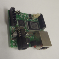
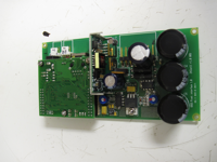
The interface between the Moxa main control computer and the Technadyne Model 20 arm actuator was a Modtronix Engineering SBC68EC single-board computer (fig. 2-1) with a custom daughterboard (fig. 2-2) to limit power drawn from the node port. Communication between the Moxa, the Modtronix, other components, and shoreside computers was via Ethernet.
The arm interface and control was designed to meet the following objectives:
1. monitor electric current drawn by the actuator
2. limit the current drawn by the actuator (overcurrent trip)
3. notify in event of an overcurrent trip
4. provide the ability to reset the overcurrent trip
5. pass measurements of current draw to the main controller
6. pass measurements from the SBG Systems IG-20 two-axis inclinometer and three-axis accelerometer to the main controller
7. pass the state of the overcurrent trip to the main controller
8. receive commands from the main controller and translate these to the control voltage required by the actuator
9. allow independent control of the arm for testing and in case of main controller failure
10. prevent electromagnetic field (EMF) noise from the actuator from affecting the rest of the system
11. provide the option to limit arm movement based on angle information from the IG-20
12. allow direct control of the arm for testing.
Modtronix provides the SBC65EC complete with Ethernet, RS232, and USB interfaces, a TCP-IP stack, customizable Web interface, and example programs. The SBC65EC uses a Microchip Technology industry-standard chip as its central processor (PIC18F6627), which allowed us to take advantage of Microchip's free compilation tools, example programs, and Web discussion forums. The Modtronix firmware design for the SBC65EC included a network boot loader that allowed newly compiled firmware and Web pages to be uploaded to the SBC65EC via Ethernet, a feature that sped development and would have allowed changes to firmware to be made from shore, if necessary. The Modtronix did not include its own real time clock.
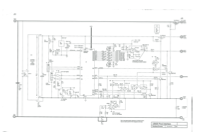
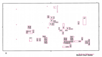
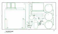
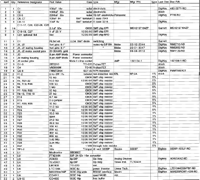
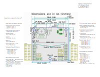
The daughterboard (fig. 2-2) was designed and built by Albert Bradley and Allan Duester at the Woods Hole Oceanographic Institution. The board schematic, component layouts, and interface to the SBC65EC are shown in figs. 2-3, 2-4, 2-5, 2-6, and 2-7. The daughterboard provided power stepped down from 24 volts of direct current (VDC) to 12 VDC for the Modtronix and IG-20, a power switching circuit for the IG-20, a second universal asynchronous receiver and transmitter (UART) used for IG-20 serial interface, a return-current-sensing circuit for the actuator, a device to automatically trip the power switch in case the actuator started drawing too much power (automatic overcurrent trip), reset for the trip, trip indicator, a resistor ladder circuit to translate digital port settings to a control voltage for the actuator, and capacitors to suppress back EMF from the actuator motor, as recommended by Technadyne.
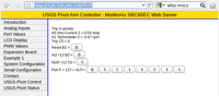
The Modtronix ran firmware written in C and cross-compiled in the MPLAB Integrated Development Environment (MPLAB Tools v. 8.63) using a Microchip MPLAB C18 compiler on a Microsoft Windows-based computer. The Modtronix monitored the power used by the arm motor, the status of a circuit breaker, and the speed of the arm motor via analog input channels, and it read the output of the arm IG-20 on an asynchronous communication port. The Modtronix posted these data on an internal Web site using the built-in SBE68EC Web Server (fig. 2-8; code in appendix 3) and broadcast these arm status data over the embedded network four times per second in user data protocol (UDP) packets. The Modtronix monitored the embedded network for arm-control commands sent by hypertext transfer protocol (HTTP) from users or by UDP from the embedded logger and controller.
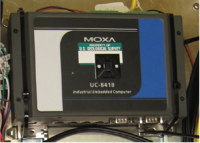
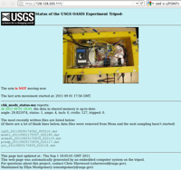
The embedded logger and controller was a Moxa UC-8418-LX (http://www.moxa.com/product/UC-8418.htm) advanced reduced-instruction set machine (ARM) (fig. 2-9) with a Linux operating system (version 2.7). Programs for the Moxa were written in C and in Linux bash shell scripting language. The C programs were cross-compiled on Ubuntu operating system (version 11.04) Linux computers running the GNU ARM tool chain for Linux (version 4.2.1.) The programs controlled arm movements and logged data from several of the instruments mounted on the arm and updated a Web page hosted on the Moxa with arm status information (fig. 2-10). Arm movements were controlled by commands issued to the Modtronix in UDP packets; these commands controlled a switch to the motor power, reset the breaker that was tripped in case of excess power draw by the motor, or specified the control voltage applied to the motor. The Moxa programs used the UDP packets sent by the Modtronix to confirm the applied control voltage and to monitor arm position (angle measured by the tilt meter), motor speed, and breaker status.
|