U.S. Geological Survey Open-File Report 2009-1137
Quaternary Geologic Framework of the St. Clair River between Michigan and Ontario, Canada
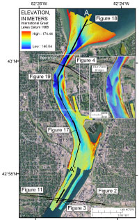
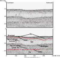
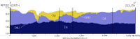
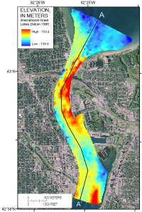
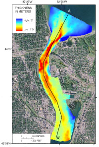
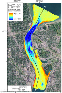
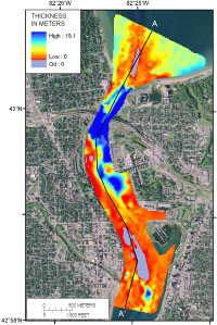
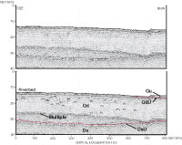
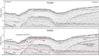
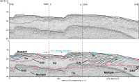
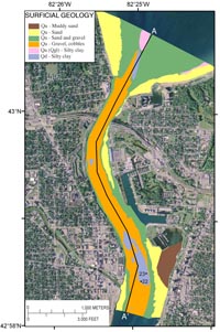
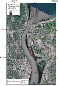
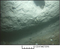
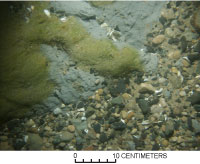
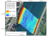
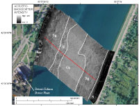
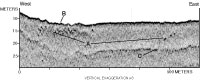
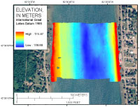
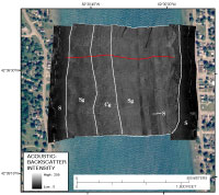
BathymetryThe processed swath bathymetry for the northernmost river area (fig. 10) shows that the lakebed of Lake Huron is relatively broad and flat, except nearshore and at the head of the St. Clair River channel. The lake floor slopes up to a nearshore shelf on both the U.S. and Canadian sides. The shelf is about twice as wide (300 m) on the U.S. side as on the Canadian side and has a series of shore oblique to perpendicular dunes that are not present on the Canadian side. The main St. Clair River channel appears to extend about 1 km to the north into Lake Huron. The bathymetry shows where the natural channel is diminished and where the shipping channel has been dredged. The natural channel has two less distinct branches to the east. The channels converge at the head of the river and divert around shoals on the U.S. side with the deepest section of the channel formed on the Canadian side. At the head of the river, immediately upstream of the Blue Water Bridges (fig. 10), the channel shifts to the center of the river and the channel constricts to approximately 220 m wide. Immediately downstream from the Blue Water Bridges, the deepest section of the channel shifts to the outer bend of the river on the U.S. side. Along the inner bend of the river, about 300 m south of the bridges, a shoal is formed on the Canadian side. The shoal extends approximately 700 m downstream. Two mid-channel linguoid bars are present in the middle of the channel in this section of the river, from the Blue Water Bridges to 1 km downstream (fig. 10 inset). These bars are each approximately 400 m long and have amplitudes of 3 to 5 m. Downstream from this location, there are no large bedforms or bars, and the channel gradually shoals upward downstream to the mouth of the Black River. Dredging since the early 1900’s has leveled the river by removing sediment from the western side, near the mouth of the Black River, and filling a deeper section of the channel on the Canadian side (Derecki, 1985). Several smaller scale morphologic features are seen in the swath bathymetry. These features are discussed in relation to acoustic backscatter later in this report. Seismic StratigraphyThree major seismic stratigraphic units and their associated unconformities (table 1) are interpreted and mapped in detail throughout the upper river study area. The seismic stratigraphy is correlated with the regional stratigraphy of Morris (2008). Where our sub-bottom profiles cross the St. Clair River Railway Tunnels (fig. 11), we correlate with the stratigraphic cross sections constructed from borings (figs. 2 and 3). The top of the Devonian shale (Ds) surface is a regional unconformity (DsU) and is the acoustic basement for our study. Above DsU is Quaternary glacial drift (Qd), which consists primarily of glacial till with interbedded glaciolacustrine deposits. An erosional unconformity (QdU) separates Qd from overlying glaciofluvial (Qgf), glaciolacustrine (Qgl), fluvial (Qf), and lacustrine (Ql) deposits (table 1). These deposits are undifferentiated over much of the study area and are referred to as Qu. A cross section along the axis of the upper river channel illustrates the general north-to-south distribution and thickness of the major stratigraphic units (fig. 12). DsU is relatively flat except for an increase in elevation along the upper 2 km of the river. Qd is thickest beneath Lake Huron and in the southern part of the study area. Qd is thin along the upper part of the river, where Qd has been partially scoured and removed, as seen in the unconformity (QdU). Qu is thickest where it fills the depression in the surface of Qd (QdU) in the upper river and in smaller depressions to the south. Qu caps Qd beneath Lake Huron or is thin to absent where the modern river channel forms at the head of the river. The elevation of DsU is mapped throughout the study area (fig. 13). Elevations range from 139 to 154 m (IGLD 85). The highest elevations are prominent along the Canadian side of the upper river and opposite the mouth of the Black River. Beneath Lake Huron, the bedrock surface dips to the northeast. The total Quaternary sediment thickness (Qd and Qu) is mapped throughout the study area (fig. 14). The sediment overburden is present throughout the study area and ranges from 8 to 31 m thick; therefore, Ds does not crop out at the river or lakebed. The overburden is thinnest beneath the modern river channel and over bedrock highs. The elevation of the upper unconformity of Qd (QdU) ranges from 139 to 174 m (fig. 15). A significant depression is observed in the surface at the head and northernmost part of the river (fig. 12). This depression extends over much of the width of the upper river. To the south, the elevation of the unconformity is relatively constant except for some smaller depressions adjacent to the Black River. The reflection at QdU typically appears as an erosional-channeled surface throughout the study area. This unconformity appears to represent erosion by glaciofluvial and possibly postglacial fluvial processes. The thickness of Qu (fig. 16) ranges from 0 to 19 m. The isopach map shows that Qu is thickest where there are depressions in the surface of Qd, except beneath Lake Huron, where Qu likely thickens towards the shore where modern lacustrine and nearshore deposits thicken. Areas of zero thickness indicate that Qu is absent or is not vertically resolved in the data. In these areas, Qd is exposed or very near the riverbed. Significant areas are in the modern channel in Lake Huron, along the outer bend of the river on the U.S. side, and in the middle of the river, just northeast of the Black River. Seismic FaciesThe character of internal reflections within Qd adds detail to the seismic stratigraphic interpretation. A seismic reflection within Qd defines the upper surface of a lower till unit (table 1), which is correlated with the top of the Catfish Creek Till. The reflection is commonly a few meters above DsU (fig. 11). The reflection is not present in all seismic profiles or may be obscured by the first multiple reflection and therefore is not mapped as a regional surface. Above this intermediate reflection, Qd typically exhibits many hyperbolic reflections (fig. 17). These reflections are likely cobbles and boulders within the glacial till. Qu exhibits distinctive internal reflections that indicate different depositional facies; however, there are no unconformities that clearly separate glaciofluvial, glaciolacustrine, fluvial, and modern lacustrine deposits. We have interpreted the depositional facies of Qu and the character of the basal unconformity (QdU) in an attempt to define the origin of deposits beneath Lake Huron and the St. Clair River. Beneath Lake Huron, the unconformity (QdU), at the base of Qu, is an uneven, channel-cut surface that formed by glaciofluvial erosion (fig. 18). We suggest that Qu above the unconformity consists of glaciofluvial deposits. Here Qu commonly exhibits discontinuous and irregular reflections that indicate multiple cut-and-fill features. Above this, Qu is more transparent and is likely glaciolacustrine in origin. Modern lacustrine deposits apparently are too thin to resolve or do not exist, except where nearshore sand deposits are seen on a few Chirp profiles. The sand is generally thin (less than 1 m thick) and discontinuous. QdU can be traced south from beneath Lake Huron into the Upper St. Clair River, where it is less irregular than the multiple cut-and-fill surfaces beneath Lake Huron (fig. 18). We suggest that a more uniform scouring of Qd occurred here, most likely by a single process of post-glacial fluvial incision. Furthermore, above the unconformity, Qu contains well-defined sequences of downstream-prograding clinoforms (figs. 18 and 19), which indicate that most of Qu was transported downstream by either glaciofluvial or fluvial processes, and the source material likely was the glaciofluvial deposits beneath Lake Huron or in part a coarse lag derived from the till (Qd). The southward-prograding clinoforms coincide with two linguoid bar features located just downriver from the Blue Water Bridges (figs. 10 and 19). The asymmetry of these bars and the southward-dipping clinoforms within them indicate they may be the result of the present flow of the river and presumably have formed during postglacial time by fluvial transport and deposition. We superimposed individual soundings from a 1971 single-beam bathymetric survey (previously converted to IGLD 85) over a sub-bottom profile that transects the bars (fig. 19). The 1971 sounding points we used were offset 5 m or less from the sub-bottom trackline. There may be other errors and uncertainty may have been introduced as a result of using the 1971 data as described by Bennion (2009). The 1971 bathymetric profile shows that a portion (about 3 m in height) of the southern bar formed after 1971. It appears that the bar formed as a result of erosion and separation from the northern bar and deposition 300 to 400 m downriver. Other than the internal structure of the bars, supporting evidence is insufficient to show whether Qu below the 1971 bathymetric profile was deposited by glaciofluvial or postglacial fluvial processes. Additional sediment-transport and modeling studies would be needed to verify the movement of these bars. Qu thins and eventually pinches out to the south where the elevation of QdU increases, except where local deposits fill channel-scoured depressions within Qd. Internal reflections indicate multiple cut-and-fill sequences within Qu. Channel depressions lead to the mouth of the Black River and may be related to the paleodrainage of that tributary. The buried channel on the Canadian side of the river, east of the mouth of the Black River, may be fill material dredged from the western side of the channel (Derecki, 1985). Surficial GeologyWe interpreted the surficial geology (bed material) (fig. 22) of the upper river study area based on stratigraphic interpretations, sub-bottom acoustic character, acoustic backscatter (fig. 21), video and photographic observations, and grain-size analysis of surface samples (fig. 9). Acoustic backscatter was the primary data source used to map the aerial extent of the different units; all other data were used to support the backscatter interpretations. Surficial units correspond to stratigraphic units and are further divided into surficial facies. Ds does not crop out, as at least 8 m of overburden is present above the bedrock. The oldest unit exposed at the river and lakebed is Qd. The remaining unit, Qu, covers most of the river and lakebed and can be subdivided into surficial facies, primarily on the basis of grain size and acoustic backscatter. Glacial till (Qd) consists of silty clay containing gravel to boulders and is exposed in three areas: in Lake Huron and the riverhead, where the modern channel has cut down into the till; at scour depressions along the river bend on the U.S. side; and in a large area just north and east of the mouth of the Black River (fig. 20). The large till exposure at the southern end of the study area was verified with video. Photographs of the till exposures indicate a rough topography with ridges, typically oriented parallel to the river current, and ledges of clay till protruding from the river bottom (fig. 22). These areas of the till that appear to be actively eroding are undercut and scoured. The till is covered in areas with patches of sand, gravel, cobbles, and boulders. Some of this material was likely derived from Qu, although we observed clast voids within the till (fig. 22), indicating that erosion of the clay material provides some of the coarse-grained lag deposit (fig. 23). In some areas, rippled sand partially covers the till, indicating active transport of sand over till. Some areas of till are stable enough to allow plant growth on the surface (fig. 23). The glacial and postglacial deposits within Qu dominate the substrate beneath Lake Huron. Other than where the till is exposed, the lake floor is primarily gravelly sand of glaciofluvial origin. In many areas, zebra mussels encrust the bottom, making it difficult to determine the sediment texture. There are two areas we interpret as glaciolacustrine deposits at the lakebed: one is a ridge of silty clay along the Canadian nearshore; the other is near the center of the lake, just east of where the modern navigation channel has been dredged. At this location, video shows areas of cohesive clay that is partially covered by a veneer of rippled sand. We also observed in video and photographs what appear to be tabular blocks of the clay material scattered over the bottom, suggesting a process in which the clay has been ripped up and deposited mostly intact. The process could be related to dredging of the nearby navigation channel. Other important substrate features beneath Lake Huron are the low-backscatter areas along both the U.S. and Canadian shores. We interpret these areas as modern nearshore sand that is actively being transported to the south by littoral currents and then by the river current. The sand is more prevalent on the U.S. shore, where it extends 150 to 350 m from shore, whereas along the Canadian shore, the sand extends 120 to 140 m from shore. Also, along the U.S. shore, beginning about 900 m north of the riverhead, a series of shore-oblique to perpendicular, low-amplitude (0.5 m) bedforms with wavelengths of 10 to 15 m are observed. These bedforms apparently are located where the influence of the river current becomes the primary influence transporting the sand. On the U.S. side, the nearshore sand narrows in width to zero at the riverhead where the sand is swept downstream, whereas on the Canadian side a narrow (less than 30 m wide) band of sand is present along the edge of the river channel. At the apex of Lake Huron and head of the river, a bathymetric high dominates the U.S. side where the deep modern channel is diverted to the Canadian side (fig. 10). The substrate grades from sand and gravel to a cobble pavement near the head of the river. The cobble pavement extends northward for about 500 m into the lake. This coarser grained, apparently more erosion-resistant ridge is likely the remnant of a glacial, ice-proximal fan deposit. The upper 2,500 m of the riverbed is dominated by a cobble pavement, except at the river bend (approximately 1,300 m downriver) on the U.S. side where areas of glacial till are exposed and on the inside of the river bend (on the Canadian side) where sand is deposited over a shoal. The cobble pavement was derived from the coarse-grained glaciofluvial deposits to the north and beneath this part of the bed. At the inside bend of the river, the flow reverses direction, creating eddies where the sand is deposited. The sand is most likely derived from nearshore sand transported along the eastern channel margin and possibly from the western shore as well. The sand deposit appears to be thin and overlies sand and gravel of glaciofluvial origin. Beyond 2,500 m downriver, the cobble pavement becomes discontinuous where till is exposed. Patches of cobbles, gravel, and boulders are present as a lag deposit over the till. Sand is deposited on the margins of the Canadian side and also on the U.S. side near the mouth of the Black River. The sand transitions into sand and gravel and finally gravel, cobbles, and boulders near the channel center. Morphology, Seismic Stratigraphy, and Surficial Geology: Marysville, MichiganThe results of a site-specific survey near Marysville, MI, show the channel morphology (fig. 24), acoustic backscatter (fig. 25), and shallow stratigraphy (fig. 26). This area is 5 km downriver from the main study area and 4 km downriver from the railway tunnels where stratigraphic control is good. The survey covers 500 m of river, from bank to bank. The Chirp profile (fig. 26) shows many point-source reflections in the sub-bottom within a few meters of the riverbed, which we interpret as cobble- to boulder-size material within the till. Apparently, little to no sediment is deposited over the till—that is, there are no sub-bottom reflections indicating sediment deposition. The topography of the riverbed is relatively rough (fig. 24) where a high concentration of the point source reflections is high. The rough topography coincides with an area of mottled high to low backscatter in the acoustic-backscatter mosaic (fig. 25), which is most likely an area of clay till or glaciolacustrine exposure with patches of gravel. The narrow (about 30 m wide) band of low backscatter (dark) along the Canadian shore is probably sand. Areas of moderate backscatter are likely sand and gravel. The high-backscatter (light) area with dunes (3- to 5-m wavelengths) is most likely gravel with sand. Unfortunately, no video, photographs, or samples are available for this location. These interpretations are based on observations from cross-river video transects (Krishnappan, 2009) from 1,200 m north and 500 m south of this area. Morphology, Seismic Stratigraphy, and Surficial Geology: Port Lambton, OntarioThe results of a site-specific survey near Port Lambton show the channel morphology (fig. 27), acoustic backscatter (fig. 28), and shallow stratigraphy (fig. 29). This survey area covers about 500 m of river, bank to bank, and is approximately 30 km downriver from Marysville. The Chirp profiles at this location show a lens of sediment deposited in the channel thalweg (fig. 29). The lens is about 3.5 m thick where the Chirp profile is shown (fig. 29) and thins both upriver and downriver. Bathymetry from 2007 indicates that the lens extends another 200 m upstream from our survey area. The lens is acoustically transparent with no internal reflections to indicate direction of transport. The source of the lens may be dredge of the western side of the channel. The sub-bottom profile shows a well-defined buried channel surface. No point-source reflections are seen for the rest of the substrate, as there are in the Marysville area. The acoustic-backscatter mosaic (fig. 28) shows areas of low backscatter along the channel margins on both sides of the river. These are likely to be areas of sand. The Chirp profiles indicate that the sand deposit is thin. Areas of moderate backscatter, including the area where the sediment lens is deposited, likely coincide with sand and gravel. The backscatter suggests that the lens has some gravel content, at least at the riverbed. The north-south bands of low backscatter within the sandy gravel unit are probably sand. At the southern end of these bands, the sand forms dunes with wavelengths of 3 to 5 m. The area of mottled high to low backscatter in the acoustic-backscatter mosaic (fig. 28), like the similar area at Marysville, is most likely an area of clay till or glaciolacustrine material with patches of gravel. The absence of point source reflections in the substrate may support the interpretation that these clays may be glaciolacustrine in origin. No video, photographs, or samples are available for this location. These interpretations are based on a cross-river video transect (Krishnappan, 2009), from 725 m south of this area. |

![]() U.S. Department of the Interior |
U.S. Geological Survey
U.S. Department of the Interior |
U.S. Geological Survey
URL: https://pubsdata.usgs.gov/pubs/of/2009/1137/html/framework.html
Page Contact Information: Contact USGS
Page Last Modified: Wednesday, 07-Dec-2016 21:58:32 EST