 |
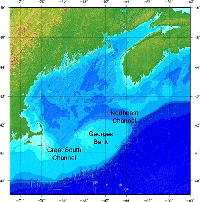
Figure 1. Shaded-relief image showing the extent of the 3-arcsecond digital
bathymetry grid for the Gulf of Maine. |
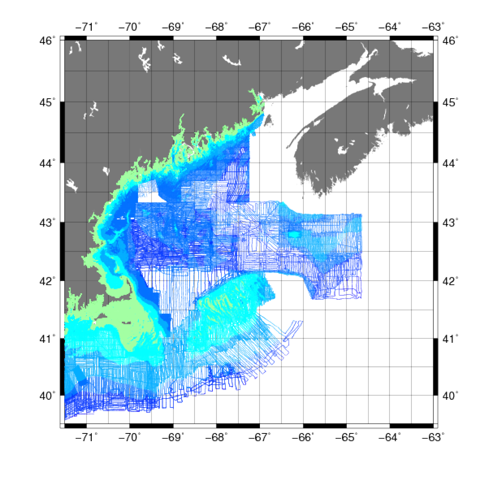 |
Figure 2. Map showing the extent of the hydrographic soundings in the Gulf of Maine from the National Oceanic and Atmospheric Administration National Geophysical Data Center survey from 1859-2008. |
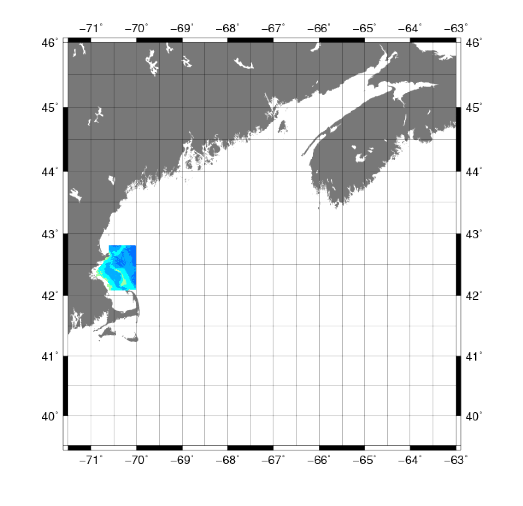 |
Figure 3. Map showing the extent of the bathymetric data from the U.S. Geological Survey Massachusetts Bay and Stellwagen Bank surveys from 1994-1998. |
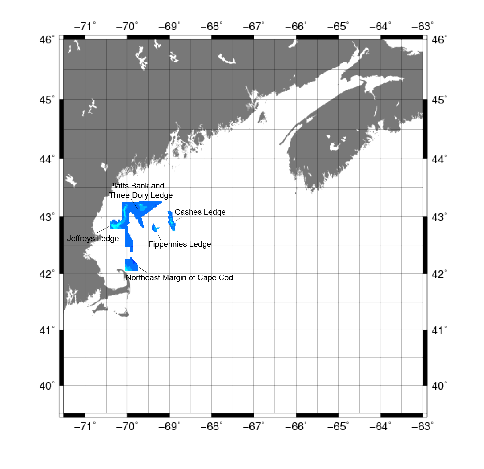 |
Figure 4. Map showing the extent of the data for the Gulf of Maine collected in 1998, 2002, and 2005
by member entities of the binational Gulf of Maine Mapping Initiative used in the construction of the digital bathymetry grid. |
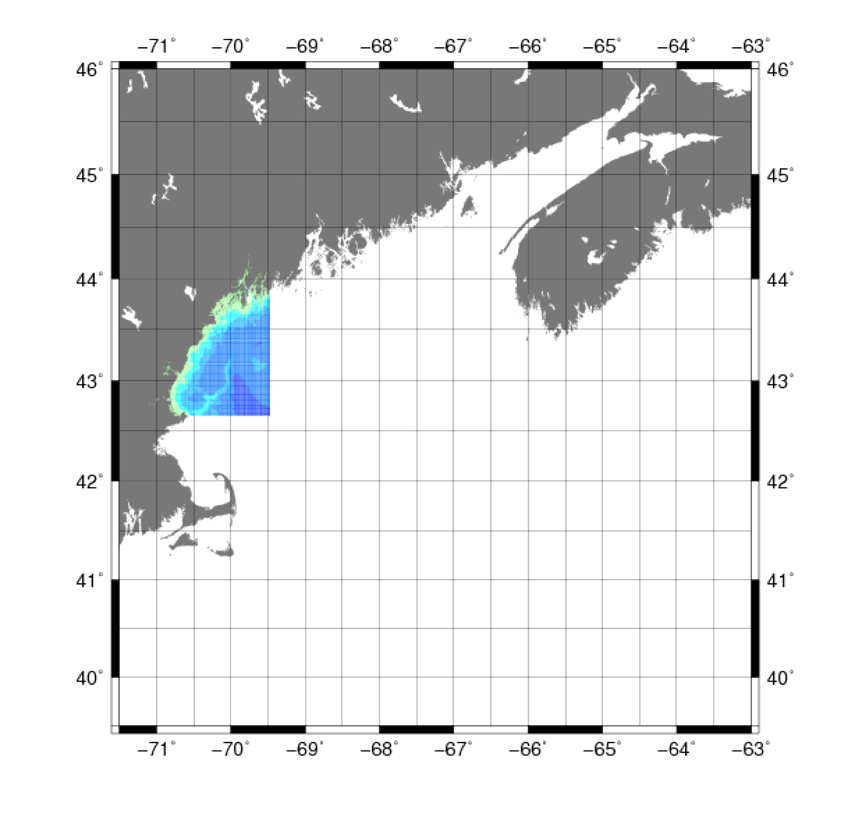 |
Figure 5. Map showing the extent of the U.S. Naval Oceanographic Office Digital Bathymetric Data Base Variable Resolution data for the Gulf of Maine used in the construction of the digital bathymetry grid. |
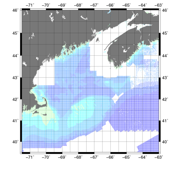 |
Figure 6. Map showing the extent of the Smith and Sandwell (1997) global topography data for the Gulf of Maine. |
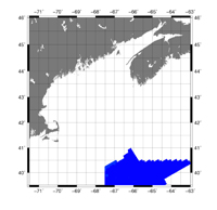 |
Figure 7A. Map showing the extent of the University of New Hampshire's far north survey for the Gulf of Maine. |
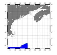 |
Figure 7B. Map showing the extent of the University of New Hampshire's north survey for the Gulf of Maine |
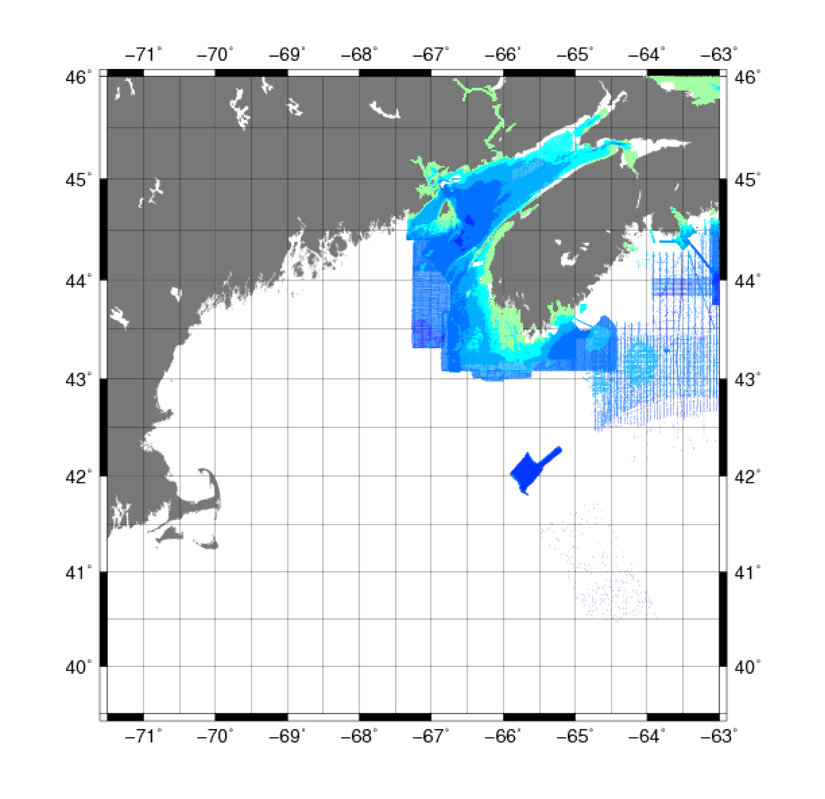 |
Figure 8A. Map showing the extent of the data for the Gulf of Maine from the Canadian Hydrographic Service’s Northwest Atlantic survey. |
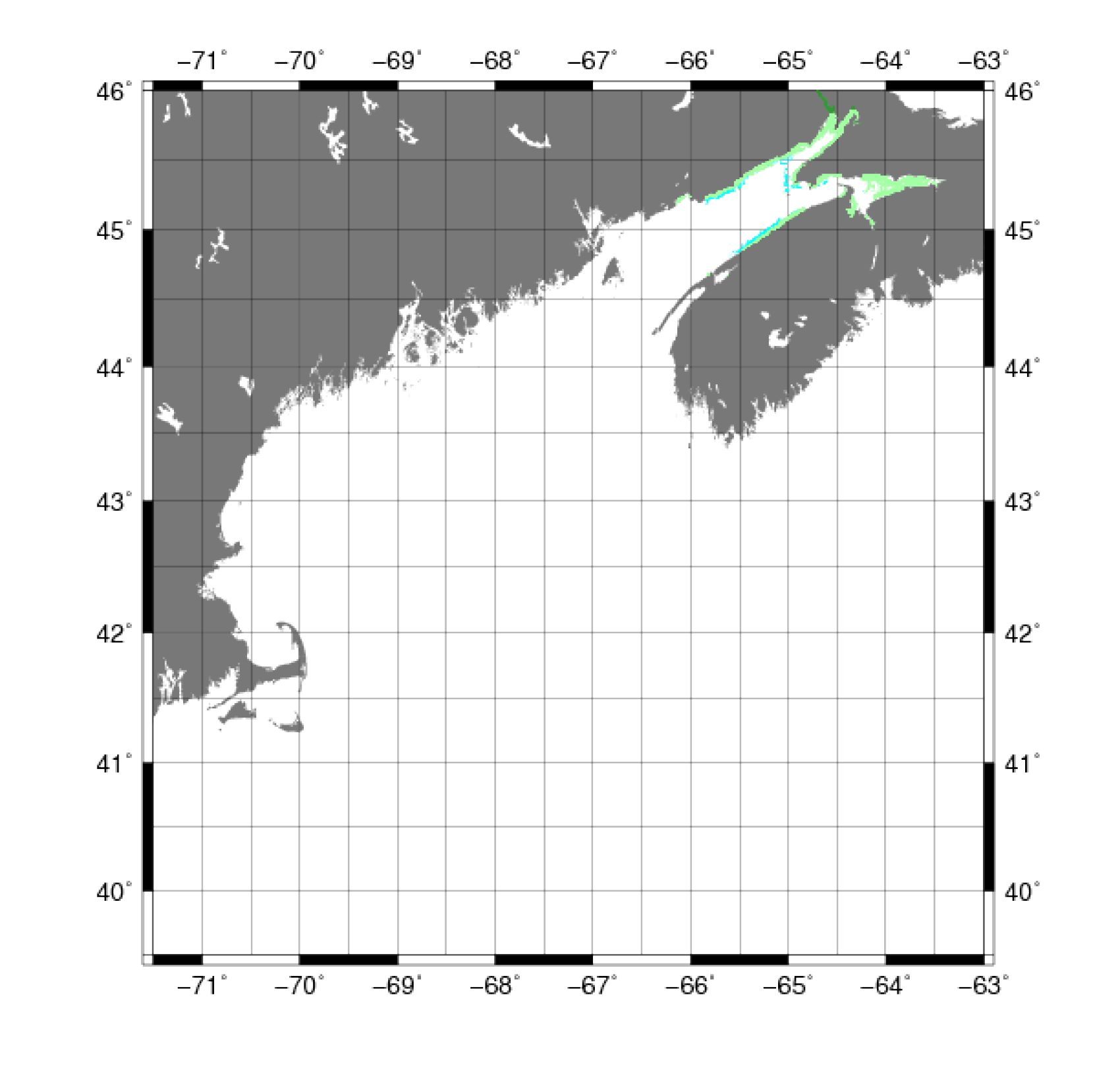 |
Figure 8B. Map showing the extent of the data for the Gulf of Maine from the University of New Brunswick’s Northwest Atlantic survey. |
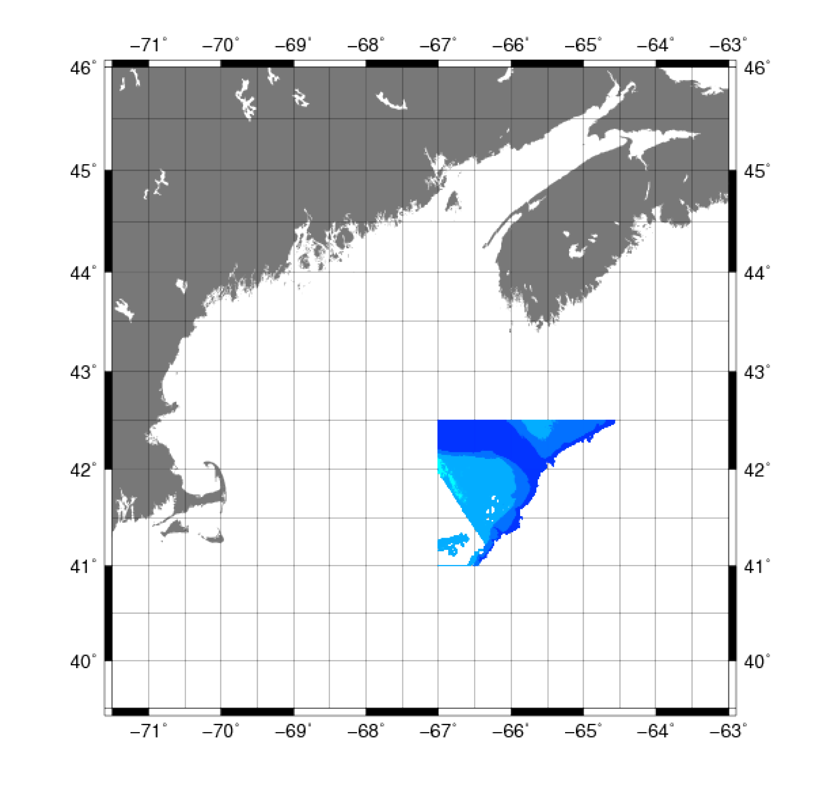 |
Figure 9. Map showing the extent of the data from the Olex three-dimensional chart system for the Gulf of Maine. |
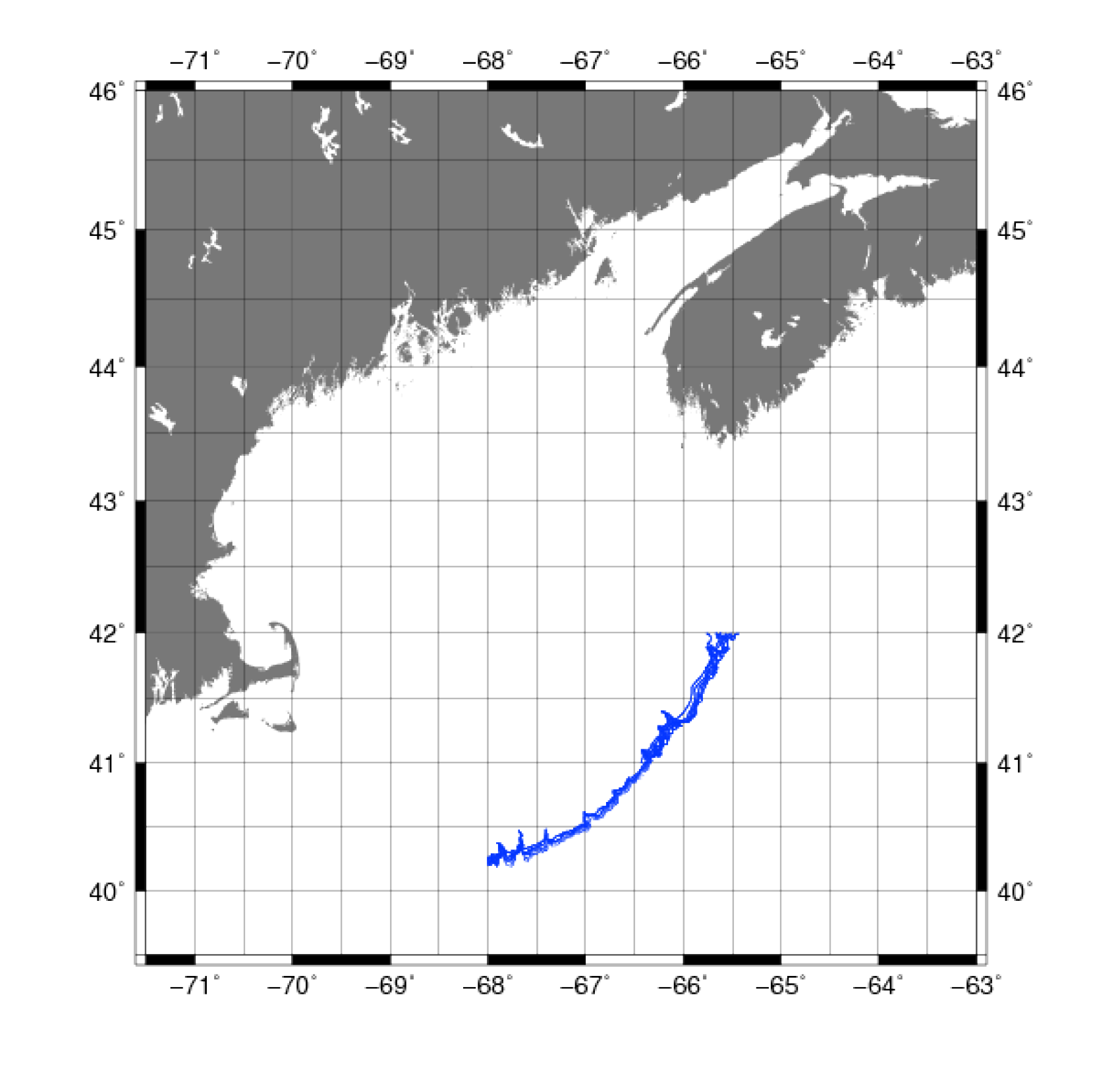 |
Figure 10. Map showing the extent of the digitized points for the Gulf of Maine from the U.S. bathymetric and fishing
charts of the National Ocean Service’s Office of Coast Survey of the National Oceanic and Atmospheric Administration. |
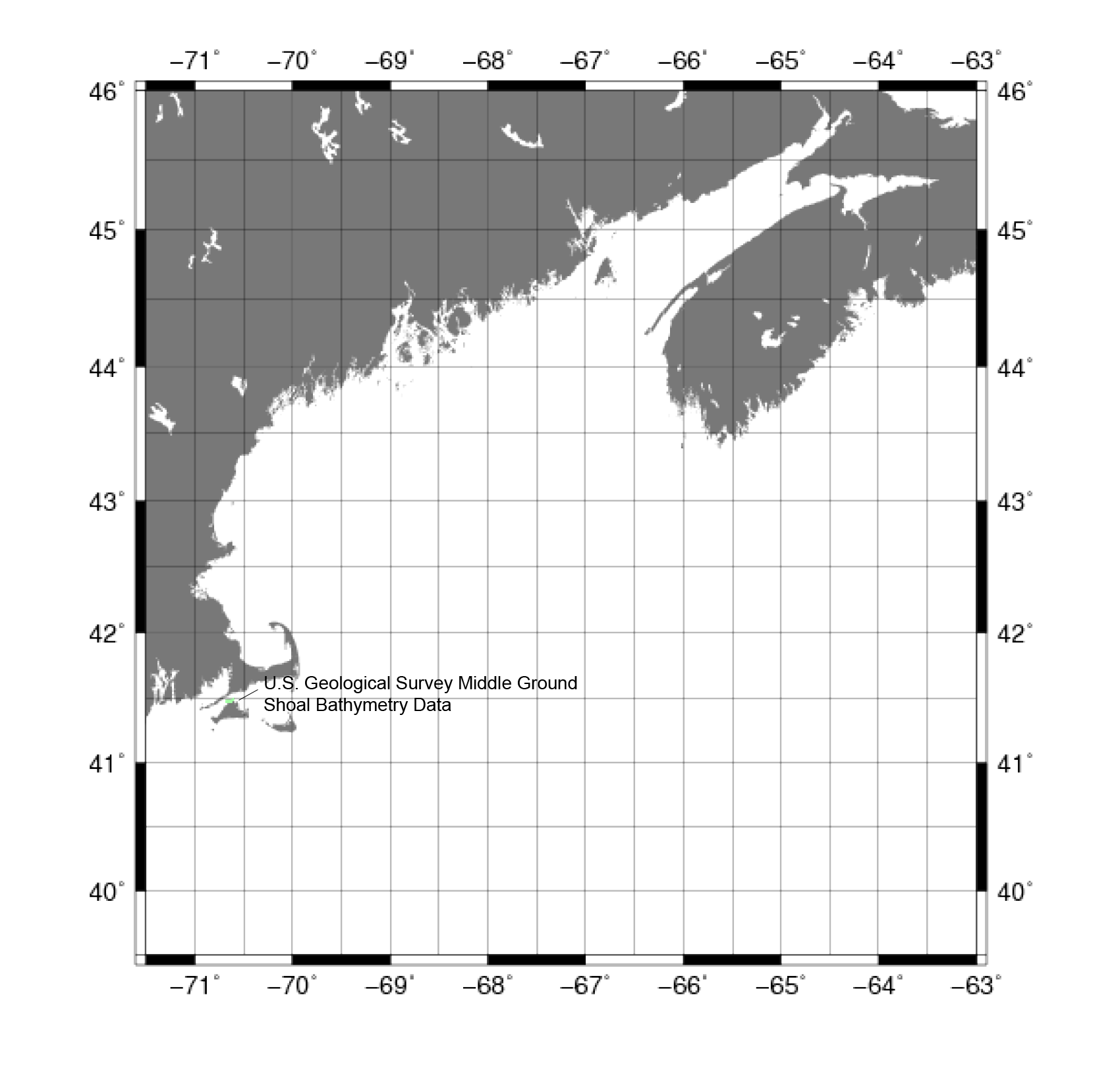 |
Figure 11. Map showing the extent of the Middle Ground shoal bathymetric data from the U.S. Geological Survey. Middle Ground is located to the north of Martha's Vineyard, Massachusetts. |
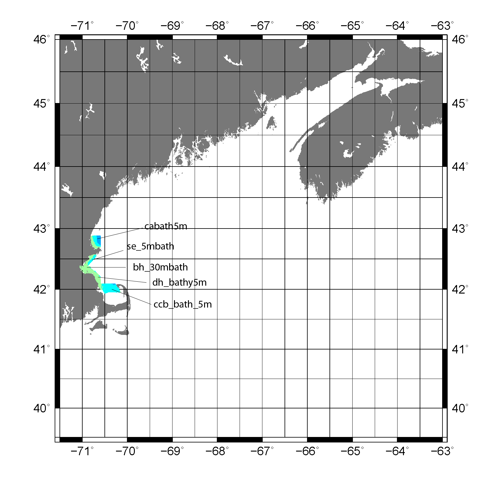 |
Figure 12. Map showing the extent of the geologic mapping data for the Gulf of Maine from the Massachusetts Seafloor Mapping Cooperative by the U.S. Geological Survey and the Massachusetts Office of Coastal Zone Management. |
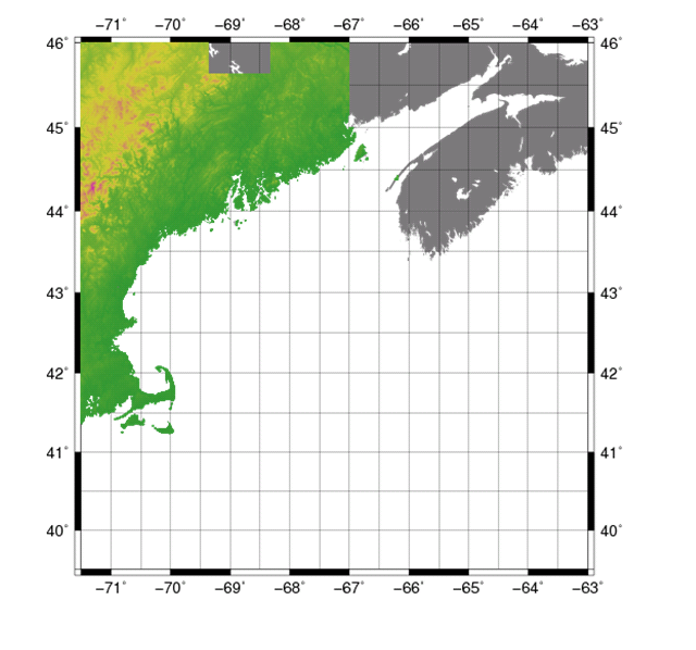 |
Figure 13. Map showing the extent of data for the Gulf of Maine from the National Elevation Dataset of the U.S. Geological Survey. |
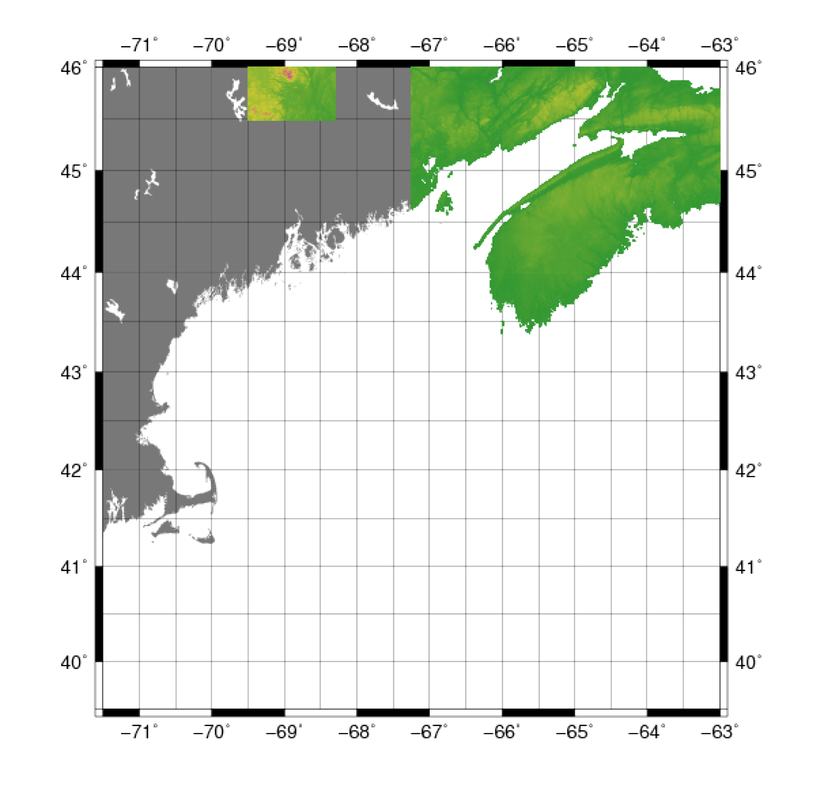 |
Figure 14. Map showing the extent of the data for the Gulf of Maine from the Shuttle Radar Topography Mission of the National Aeronautics and Space Administration. |
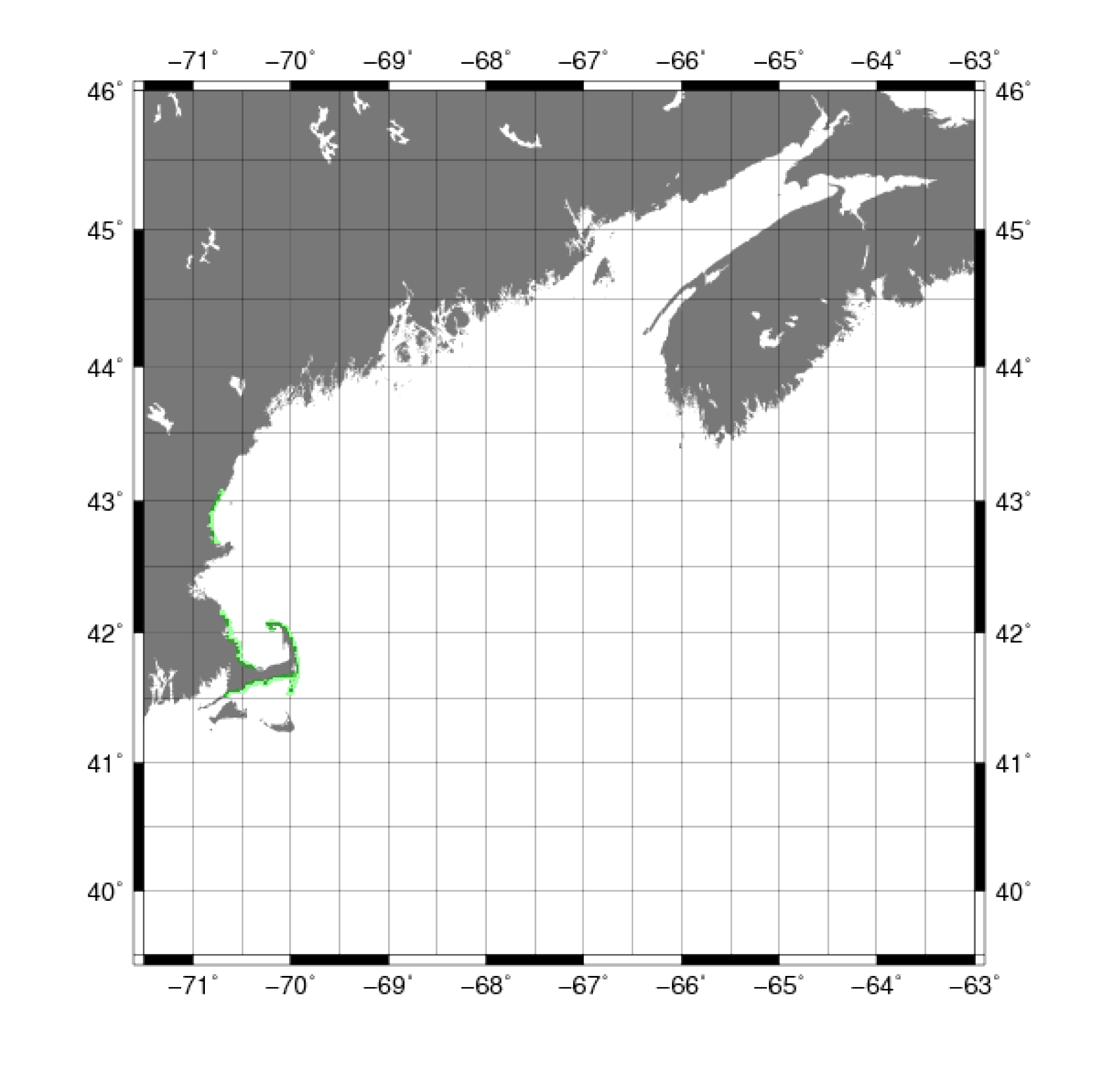 |
Figure 15. Map showing the extent of the light detection and ranging (LIDAR) data for the Gulf of Maine from the National Ocean Service’s Coastal Services Center of the National Oceanic and Atmospheric Administration. |
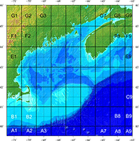 |
Figure 16. Map showing the locations of the working sub-regions used in constructing the Gulf of Maine bathymetry grid. |
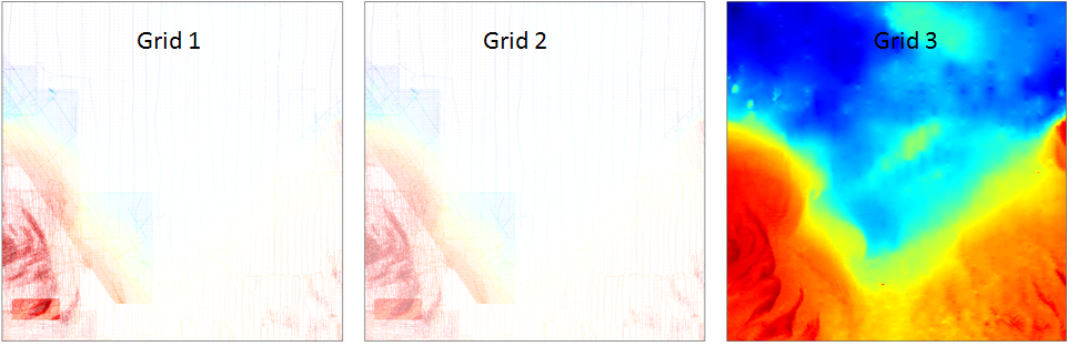 |
Figure 17. Bathymetric map segments showing an example of the comparison between the different stages of processing of bathymetric data. Grid 1 shows unfiltered, input data.
Grid 2 shows data filtered by blockmedian with a grid cell size of 3-arcseconds. Grid 3 shows the final product created by data filtered by
blockmedian and run through a surface-fitting routine. |
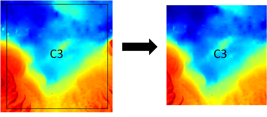 |
Figure 18. Bathymetric map segments illustrating the use of the Generic Mapping Tool grdcut command.
Final grid section C3 (69°30' to 68°30'W and 41° to 42°N) is extracted from working sub-region C3 (69°36' to 68°24'W and 40°54 to 42°6'N). |
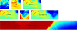 |
Figure 19. Bathymetric map segments showing the row sub-region pasting process using
the Generic Mapping Tool grdpaste command. A base grid was created using sub-regions C1 and C2.
Grid C3 was added, until row C, the composite bathymetric map segment was completed. |
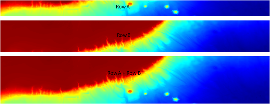 |
Figure 20. Bathymetric map segments showing the row sub-region pasting process using
the Generic Mapping Tool grdpaste command. Row A was added to row B to produce a composite base grid.
This process was then repeated for rows C through G (not shown in figure) until the grid was completed. |


